Full resolution - ThePlaz.com
Full resolution - ThePlaz.com
Full resolution - ThePlaz.com

Create successful ePaper yourself
Turn your PDF publications into a flip-book with our unique Google optimized e-Paper software.
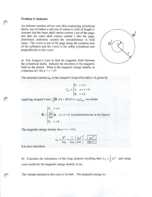
Problem 5: Inductor<br />
An inductor consists of two very thin conducting cylindrical<br />
shells, one of radius a and one of radius b, both of length h.<br />
Assume that the inner shell caITies current lout of the page,<br />
and that the outer shell carries current 1 into the page,<br />
distributed uniformly around the circumference in both<br />
cases. The z-axis is out of the page along the <strong>com</strong>mon axis<br />
of the cylinders and the r-axis is the radial cylindrical axis<br />
perpendicular to the z-axis.<br />
b<br />
I<br />
®<br />
a) Use Ampere' s Law to find the magnetic field between<br />
the cylindrical shells. Indicate the direction of the magnetic<br />
field on the sketch. What is the magnetic energy density as<br />
a function of r for a < r < b?<br />
The enclosed current I elle in the Ampere's loop with radius r is given by<br />
1"" = l~ : ~: ~ < b<br />
0, r >b<br />
Applying Ampere's law, []B.ds = B(2nr) = floI"c' we obtain<br />
B - __<br />
0, r b<br />
a < r < b (counterclockwise in the figure)<br />
The magnetic energy density for a < r < b is<br />
It is zero elsewhere.<br />
b). Calculate the inductance of this long inductor recalling that U 8<br />
=~L1 2<br />
your results for the magnetic energy density in (a).<br />
2<br />
and using<br />
The volume element in this case is 2nrhdr. The magnetic energy is :
U/J = fU /JdVol = brr PO;', ) 21Ch I'dI' = Po/ ' h In (~)<br />
v lls1C r 41C a<br />
Since U H = Po [ ' lln(~ ) =.!:.. LJ' , the inductance is<br />
41C a 2<br />
L = Poh In(~)<br />
21C a<br />
c) Calculate the inductance of tlus long inductor by usmg the formula<br />
(I) = LJ = f B· dA and your results for the magnetic fi eld in (a). To do this you<br />
ope" .mrfacl!<br />
must choose an appropriate open surface over whi ch to evaluate the magnetic flux. Does<br />
yo ur result calculated in this way agree with your result in (b)?<br />
cil' /<br />
/<br />
[ a<br />
I<br />
~<br />
~ ./<br />
The magnetic field is perpendicular to a rectangular<br />
surface shown in the figure. The magnetic flux tlu'ough a<br />
thin strip of area dA = ldr is<br />
,<br />
- -- --<br />
r -,<br />
-<br />
B- ...<br />
, ,<br />
i- - - - -<br />
-====:::<br />
~-... ::::~,<br />
"<br />
-' -- -,<br />
'~<br />
, , , ,<br />
~ - - -"" , -<br />
....... .. ..<br />
"-'0-- --------<br />
I<br />
Thus, the total magnetic flux is<br />
Thus, the inductance is<br />
whi ch agrees with that obtained in (b).<br />
~tJel/<br />
'M -{)<br />
- 90 fo<br />
d
Problem 6: Trying to open the switch on an RL Circuit<br />
The LR circuit shown in the figure contains a resistor R, and an inductance L in series<br />
with a battery of emf Go. The switch S is initially closed. At I = 0, the switch S is opened,<br />
so that an additional very large resistance R, (with R, D R,) is now in series with the<br />
other elements.<br />
I<br />
•<br />
(a) If the switch has been closed for a long time before I = 0, what is the steady current<br />
10 in the circuit?<br />
There is no induced emf before I = O. Also, no current is flowing on R2. Therefore,<br />
I -~ o-<br />
R'<br />
(b) While this current 10 is flowing, at time I = 0, the switch S is opened. Write the<br />
differential equation for /(1) that describes the behavior of the circuit at times I ~ O.<br />
Solve this equation (by integration) for Jet) under the approximation thatG o = O.<br />
(Assume that the battery emf is negligible <strong>com</strong>pared to the total emf around the circuit<br />
for times just after the switch is opened.) Express your answer in terms of the initial<br />
current /0' and R" R" and L.<br />
The differential equation is<br />
d/(I)<br />
Go -/(t)(R, +R,)=L-<br />
dl<br />
Under the approximation that Go = 0, the equation is<br />
- I(I)(R, + R,) = L dl(t)<br />
dl<br />
The solution with the initial condition /(0) = 10 is given by
(R, +R,) I)<br />
1(1) = 10 exp( L<br />
(c) Using your results from (b), find the value of the total emf around the circuit (which<br />
from Faraday's law is -Ldl / dl) just after the switch is opened. Is your assumption in (b)<br />
that Go could be ignored for times just after the switch is opened OK?<br />
dIU)1<br />
G=-L--<br />
dt ,.0<br />
=Io(R, +R,)<br />
S· mce 10 =<br />
Go<br />
,<br />
R '<br />
Go (R, )<br />
G= - (R, +R, )= 1+- Go »Go<br />
R, R,<br />
(": R, »R,)<br />
Thus, the assumption that Go could be ignored for times just after the switch is open is<br />
OK.<br />
(d) What is the magnitude of the potential drop across the resistor R, at times t > 0, just<br />
after the switch is opened? Express your answers in terms of Go , R" and R, . How does<br />
the potential drop across R, just after t = 0 <strong>com</strong>pare to the battery emf Go, if<br />
R, =100R,?<br />
The potential drop across R2 is given by<br />
If R, = 1 OOR"<br />
R, (R, )( R, ) R,<br />
L'>.V, = G= 1 +- Go =-Go<br />
R, + R, R, + R, R, R,<br />
i1V 2 = 100 Eo<br />
This is why you have to open a switch in a circuit with a lot of energy<br />
stored ill the magnetic field very carefully, or you end lip very dead!!
Problem 7: Le Circuit<br />
An inductor having inductance L and a capacitor having capacitance C are connected in<br />
series. The current in the circuit increase linearly in time as described by 1= KI. The<br />
capacitor initially has no charge. Determine<br />
(a) the voltage across the inductor as a function of time,<br />
The voltage across the inductor is<br />
dI d<br />
£ =-L-=-L-(KI)=-LK<br />
I. dl dl<br />
(b) the voltage across the capacitor as a function of time, and<br />
Using 1= dQ , the charge on the capacitor as a function oftime may be obtained as<br />
dl<br />
, , 1<br />
Q(I) = fIdI' = fKI'dt' =-KI'<br />
o 0 2<br />
Thus, the voltage drop across the capacitor as a function of time is<br />
o<br />
KI'<br />
L'>V = -= =--<br />
c C 2C<br />
(c) the time when the energy stored in the capacitor first exceeds that in the inductor.<br />
The energies stored in the capacitor and the inductor are<br />
The two energies are equal when<br />
Uc = ~C( L'>Vc )' = ~C( - ~~ J = ~~'<br />
U =~LI ' =~L(KI) ' =~LK ' I'<br />
I. 2 2 2<br />
K' " 1<br />
_1- = _ LK' ("<br />
8C 2<br />
=:;. I' = 2~ LC<br />
Therefore, U c > UI. when I > t' .
Problem 8: LC Circuit<br />
(a) Initially, the capacitor in a series LC circuit is charged. A switch is closed, allowing<br />
the capacitor to discharge, and after time T the energy stored in the capacitor is onefourth<br />
its initial value. Determine L if C and T are known.<br />
The energy stored in the capacitor is given by<br />
Thus,<br />
o 1 2 0 COHO 1 '<br />
c 2C 2C 2C 0<br />
U (I) =.d...L = ( )'<br />
_ 0 0 = Q o cos' W 1<br />
cos' woT cos' woT<br />
=---"-<br />
cos' (O) 4<br />
I<br />
=> cos woT = -<br />
2<br />
which implies that<br />
woT = tr rad = 60° . Therefore, with Wo = ~ ,<br />
3 '\fLC<br />
we obtain<br />
(b) A capacitor in a series LC circuit has an initial charge Q o and is being discharged.<br />
The inductor is a solenoid with N turns. Find, in terms of Land C, the flux through each<br />
of the N turns in the coil at time I, when the charge on the capacitor is Q(t).<br />
We can do this two ways, either is acceptable. First,we can make the explicit assumption that<br />
Q(/) = Q o COSWol and the total flu x through the inductor is L1 = L ~7 = -LwoQo sin Wol<br />
Therefore the flux through one turn of the inductor at time 1 is C!>o"'t"m = - LwoQ o sin Wol<br />
N<br />
or in terms of Land C, (j).,tot"m = -~ ~ sin Wol. Or second, we can simply leave Q(I)<br />
as an unspecified function of time and write (using the same arguments as above) that<br />
C!><br />
one lum<br />
=.!:... dQ<br />
N dl<br />
(c) An LC circuit consists of a 20.0-mH inductor and a 0.500-,uF capacitor. If the<br />
maximum instantaneous current is 0.100 A, what is the greatest potential difference<br />
across the capaci tor?
The greatest potential difference across the capacitor when U c ma < = Ul. m , ., ' or<br />
_ iLl _ (20.0mH) (<br />
Vema, - Vc ma, -<br />
)_<br />
(0.500 ilF) O.lOOA - 20 V
4(27<br />
c {aY><br />
~tJ9<br />
tor ~(di1 \lQ<br />
~ (1~<br />
PRS: Ampere's Law<br />
PRS Answer: Ampere's Law<br />
J<br />
Integrating B around the loop shown gives us:<br />
1. a positive number<br />
2. a negative number<br />
0% 3 zero<br />
r<br />
-<br />
Answer: 3. Total penetrating current is zero,<br />
so<br />
""·1<br />
PRS: Ampere's Law<br />
PRS Answer: Ampere's Law<br />
J<br />
Integrating 8 around the loop shown gives us:<br />
0% 1. a positive number<br />
0% ® a negative number<br />
0% 3. zero<br />
vp<br />
PRS: Loop<br />
The magnetic field through<br />
a wire loop is pointed<br />
upwards and increasing<br />
with time. TneinducM<br />
current in the coil is<br />
b-A- am·.;<br />
o t~ ,. I/"ffr(<br />
PRS:Loop<br />
The magnetic field through<br />
a wire loop is pointed<br />
upwards and decreasing<br />
with time. The lifciuced<br />
current in the coil is ~ 0<br />
dii < 0<br />
J,<br />
0% 1. Clockwise as seen from the top<br />
00/. @)counterclockwise<br />
t'iurub'r')<br />
,<br />
1 (\.t \;<br />
(t,<br />
0J<br />
~ lIl./14 o'\ltr \,., ~ '1 -C\<br />
pl. 7<br />
PRS Answer: Loop<br />
Answer: 2. Induced current<br />
is counterclockwise<br />
ii .. d«t;'",,_-'-<br />
ct>0ft0I . 8"",t<br />
6-=t--f§<br />
IN . r", (<br />
PRS: Loop Below Magnet<br />
~<br />
~~<br />
A conducting loop is below a magnet and moving<br />
downwards. This induces a current as pictured. The<br />
I ds x B force on the coil is ..--<br />
0% G Up<br />
2. Down<br />
0% 3. Zero<br />
m PRS: Loop in Uniform Field<br />
B"", O 0 0 0 0 0 0 0<br />
o 0 0Er ' I 00<br />
00 0 00 · 00<br />
---+ v<br />
A rectangular wire loop is pulled thru a uniform B field<br />
penetrating its top half, as shown. The induced<br />
current and the force and torque on the loop are:<br />
:4 1. Current CW, Force Left, No Torque<br />
1'0 2. Current CW, No Force, Torque Rotates CCW<br />
1'0 3. Current CCW, Force Left, No Torque<br />
1'0 4. Current CCW, No Force, Torque Rotates CCW<br />
:4 ~ No current, force or torque "'HI<br />
PRS Answer: Loop Below Magnet<br />
Answer: 1. Force is Up<br />
More detail:<br />
Induced current is counter-clockwise to oppose<br />
drop in upward flux.<br />
This looks like a ciiP-m..e facing upward. so it is<br />
l attracted to the ~<br />
;) r {yll + VvV) ~v til<br />
>1 fhcd f~II(,<br />
PRS Answer: Loop in Uniform Field<br />
B.",O 0 0 0 0 0 0 0<br />
o 00Er' I 00<br />
00000 · 00<br />
---+ v<br />
Answer: 5. No current, force or torque<br />
The motion does not change the magnetic flux. so<br />
Faraday's Law says there is no induced EMF, or<br />
current, or force, or torque.<br />
Of course, it we were pulling at all up or down there<br />
would be a force to oppose that motion.<br />
Class 31<br />
2
. .<br />
A coil moves up<br />
from underneath a<br />
magnet wlih its<br />
north pole pointing<br />
upward. The<br />
current in the coil<br />
and the force on the<br />
coil:<br />
- PRS: Faraday's Law: Loop<br />
0% 1. Current dockwise; force up<br />
0% ~ Current counterclockwise; force up<br />
0% ff:) Current clockwise; force down<br />
0% ~ Current counterclockwise; force down<br />
Jo -((( ~SIIAj<br />
PRS: Circuit<br />
A circuit in the form of a<br />
rectangular piece 01 wire is<br />
pu~~awalJ rQm a long<br />
wire rry'!]!LCJJJIent I in<br />
the direction shown in the<br />
sketch. The induced<br />
current in the rectangular<br />
circuit is<br />
0% (1) Clockwise<br />
0% ~ Counterclockwise<br />
3. Neither, the current is zero<br />
0%<br />
A square coil rotates in a<br />
magnetic field directed to<br />
the right. At the time<br />
shown, the current in the<br />
square, when looking<br />
down from the top of the<br />
square loop, will be<br />
0%<br />
0%<br />
,..<br />
0%<br />
~<br />
(01' Cf'<br />
PRS: Generator<br />
. . Clockwise<br />
Counterclockwise<br />
. Neither, th e current is zero<br />
4. I don't know<br />
."."<br />
(<br />
Q po5eJl<br />
PRS Answer: Faraday's Law: Loop<br />
Answer: 3. Current is clockwise; force is down<br />
The clockwise current ~<br />
creates a self-field < 'Y<br />
downward, trying to offset<br />
the increase of magnetic<br />
flux through the call as it -:dJ:~<br />
'<br />
moves upward into stronger I 0<br />
fields (Lenz's Law) , -,-<br />
The I dl x B lorce on the coil is a force which is<br />
trying to keep the flux through the coil from<br />
increasing by slowing it down (Lenz's Law again).<br />
PRS Answer: Circuit<br />
Answer: 1. Induced current ''''lTl>tqli 1<br />
'1<br />
-0<br />
isc~se<br />
B due to I is into ~; the flux ,1 _II ' L<br />
through the circuit ue to th at field<br />
d.§£reases as the circuit moves<br />
away.fPo the induced current is<br />
clockwise (to make a B into the<br />
page) \; b" 'Oo?<br />
Note: I .. dl x B force is left on the left segment and<br />
right on the right, but the force on the left is bigger.<br />
So the net force on the rectangular circuit is to the<br />
left, again trying to keep the flux from decreasing by<br />
slowina the circuit's motion<br />
fl"Oi hxJ- J,' h<br />
6 ~ wire.<br />
PRS Answer: Generator<br />
Answer: 1. Induced current<br />
is counterclockwise<br />
Flux through l o op~ as<br />
normal rotates aJ~To<br />
try to keep flux from decreasing ,<br />
induced current will be CCW,<br />
rryrrrg1
PRS: Stopping a Motor<br />
Consider a motor (a loop of wire rotating in a B<br />
field) which is driven at a constant rate by a<br />
battery through a resistor.<br />
Now grab the motor and prevent it from<br />
rotating. What happens to the current in the<br />
circuit?<br />
""< 6) Increases<br />
... 2 . Decreases<br />
""<br />
3. Remains the Same<br />
• % 4 . I don't know<br />
fi ..<br />
PRS Answer: Stopping a Motor<br />
Answer: 1. Increases<br />
When the motor is rotating in a magnetic field<br />
an EMF is generated which opposes the<br />
motion, that is, it reduces the current. When<br />
the motor is stopped that back EMF disappears<br />
and the full voltage of the battery is now<br />
dropped across the resistor - the current<br />
increases. For some motors this increase is<br />
very significant, and a stalled motor can lead to<br />
huge currents that burn out the windings (e.g.<br />
your blender).<br />
n,.<br />
rn;gJ.<br />
~ V1\7 QUI<br />
PRS: Faraday Circuit<br />
gnelie field B penetrates this<br />
circuit outwards, and is increasing<br />
at a rale such that a current of 1 A<br />
A<br />
R='OQ<br />
is induced in the circuit (which<br />
:: ~/ ~<br />
direction?). > / ""' ><br />
The potential difference VA-VB is: "" R='OOQ ""<br />
0% 1. .10 V<br />
B<br />
0% 2. -10 V<br />
0% 3. +100 V<br />
,.. 4. -100 V<br />
0% 5. +110 V<br />
0% s. -1 ' 0 V<br />
0% 7. .90V<br />
0% 8. -90 V<br />
0% / 9.1 None of the above . '1 11<br />
...... I<br />
~<br />
PRS Answer: Faraday Circuit<br />
A<br />
Answer: 9. None of the above<br />
The question is mean ingless .....<br />
There is no suen th ing as<br />
potential difference when a<br />
changing magnetiC flux is present.<br />
By Faraday's law, a non-conservative E is<br />
induced (that is, its integral around a closed<br />
loop is non-zero). Non-conservative fields<br />
can't have potentials associated with them.<br />
~" n<br />
PRS: Voltage Across Inductor<br />
'"". switch d""" is closed """'.. at t = O. A I ~ R ,.<br />
voltmeter hooked across =L ,.<br />
the inductor will read:<br />
'"'<br />
V L<br />
= ee .,,, 1(I{.i(??~'r~<br />
VL = e(1 - e-"') J(!C,-ec;''"!J<br />
V L<br />
=0<br />
4. I don't know<br />
E<br />
\ b<br />
Class 31<br />
f- T(( -Lft ~ O<br />
d j<br />
= r-1 ~<br />
PRS Answer: V Across Inductor<br />
Answer: 1. V L<br />
= ee-'/' ~ 0<br />
The inductor 'Works hard" at .::L .. L ~'<br />
first , preventing current flow, -T£<br />
then u r~ as th.e ~urre n t ~'-_'" b<br />
be<strong>com</strong>es constant In time.<br />
Although "voltage differences" between two<br />
pOints isn't <strong>com</strong>pletely meaningful now, we<br />
certainly can hook a voltmeter across an<br />
inductor and measure the EMF it generates.<br />
( J((f1\1<br />
w'd'<br />
Sto..J7 t<br />
• l •<br />
4
PRS: LC Circuit<br />
Consider the LC circuit at<br />
right. At the time shown the<br />
current has its ~<br />
value. At this time<br />
-<br />
D<br />
L<br />
c- l<br />
0% ~ The charge 00 the capacitor has its maximum value""" 11\ It). }LJt<br />
'" ~ The magnetic field is zero<br />
0% The eleclrlc field has its maximum value .-!!JIt{1<br />
. . J<br />
-<br />
f<br />
0% 4. The charge on the capaCitor IS zero<br />
0% . Don't have a clue<br />
~I~" (e~r''w)<br />
td<br />
'3 rv \'Vt'lo ~U '( <<br />
PRS: LC Circuit<br />
In the LC circuit at right the e<br />
current is in the direction<br />
==<br />
shown and the charges on<br />
the capacitor have the signs F<br />
shown. At this time,<br />
-Q +Q<br />
:r<br />
0% @ I is increasing and Q is increasing<br />
0% I is increasing and Q is decreasing<br />
0% 3. I is decreasing and Q is increasing<br />
'"<br />
'"<br />
4. I is decreasing and Q is decreasing<br />
5. Don't have a clue<br />
11'<br />
J\'C~'el/<br />
()J<br />
,,~<br />
PRS Answer: LC Circuit<br />
D<br />
Answer: 4. The current is<br />
maximum when the charge<br />
on the capacitor is zero<br />
Current and charge are exactly 90 degrees out of<br />
phase in an ideal LC circuit (no resistance). so when<br />
the current is maximum the charge must be<br />
identically zero.<br />
t1,now<br />
(htij f; € tl<br />
f ~C'.)\ vd lJ~<br />
PRS Answer: LC Circuit<br />
Answer: 2. I is increasing;<br />
Q is decreasing<br />
With current in the direction<br />
shown, the capacitor is<br />
discharging (Q is decreasing).<br />
But since Q on the right plate is positive, I must be<br />
increasing. The positive charge wants to flow, and<br />
the current will increase until the charge on the<br />
capacitor changes sign. That is, we are in the first<br />
quarter period of the discharge of the capacitor,<br />
when Q is decreasing and positive and I is<br />
increasing and positive.<br />
t"·»<br />
.)'1'<br />
~-f ,.<br />
4."t\\ '(I!J<br />
(}\f\'1 ",,.>/<br />
PRS: LC Circuit<br />
The plot shows the charge ' ..... =-.---,="<br />
on a c~ r (black curve) ~ .<br />
and the current through it<br />
(red curve) after you turn<br />
off the power supply. If yOU ! 4J<br />
J~ I<br />
r .... lfOS)<br />
" 0<br />
C~v'(tE<br />
Core. l' L<br />
~O wht-ti<br />
PRS Answer: LC Circuit<br />
Answer:<br />
1. T Lag will increase 11 ..... '<br />
, I ·<br />
s~~· t++++-I~+-I+J'<br />
!-<br />
. ,,,,.~<br />
---.:.--::.:--;i,;,'0>'<br />
,-....<br />
Putting in a core increases the inductor's<br />
inductance and hence decreases the natural<br />
frequency of the circuit. Lower frequency means<br />
longer period. The phase will remain at 90' (a<br />
quarter period) so T lag will increase.<br />
---.oc.<br />
\vtl l Tl-~<br />
1,[ l; vU{<br />
}W4>" 7' L<br />
h,,~~erSr Mv' Jcz ) { el\o(l,V\ lp/ th 'q<br />
J
If you increase the<br />
resistance in the circuit<br />
what will happen to rate<br />
of decay of the pictured<br />
amplitudes?<br />
PRS: LC Circuit<br />
.'0, .,01,<br />
'" @ It will increase (d~cay ';;o7e'r;Pidlyj<br />
2. It will decrease (decay less rapidly)<br />
'"<br />
3. It will stay the same<br />
-<br />
4. I don't know<br />
PRS Answer: LC Circuit<br />
Answer: 1. It will increase I.OO.=_.----_~===='~<br />
(decay more rapidly) I~·<br />
., i<br />
~uo, ,. .. ,<br />
£~. "1<br />
, ",-oo,!-. - -.:--...,.:--,1,.;.'0,<br />
-...<br />
Resistance is what dissipates power in the circuit<br />
and causes the amplitude of oscillations to<br />
decrease. Increasing the resistance makes the<br />
energy (and hence amplitude) decay more rapidly.<br />
Class 31<br />
6
Summary of Class 31<br />
Exam 3 Information<br />
TEST THREE Thursday Evening April 29 from 7:30-9:30 pm.<br />
The Friday class immediately following is canceled because of the evening exam.<br />
Please see announcements for room assignments for Exam 3.<br />
What We Expect From You On The Exam<br />
I. An understanding of how to calculate magnetic fields in highly symmetric<br />
si tuations using Ampere's Law, e.g. as in the Ampere's Law Problem Solving<br />
Session.<br />
2. An understanding of how to use Faraday's Law in problems involving the<br />
generation of induced EMF's. You should be able to formulate quantitative<br />
answers to questions about energy considerations in Faraday's Law problems, e.g.<br />
the power going into ohmic dissipation <strong>com</strong>es from the decreasing kinetic energy<br />
of a rolling rod, etc.<br />
3. The ability to calculate the inductance of specific circuit elements, for example<br />
that of a long solenoid with N turns, radius a, and length L.<br />
4. An understanding of simple circuits. For example, you should be able to set up the<br />
equations for multi-loop circuits, using Kirchhoffs Laws that include inductors.<br />
You should be able to understand and graph the solution to the differential<br />
equations for a circuit involving a battery, resistor, and inductor, and a circuit just<br />
involving a resistor and inductor. You should be ab le to <strong>com</strong>pare and contrast RL<br />
and RC circuits, and should understand the meaning of time constants ('t = LlR, 't<br />
=RC)s<br />
5. An understanding of the concept o[ energies stored in magnetic fields, that is<br />
U = 1 u ' for the total magnetic energy stored in an inductor, and liB = 2~ 8' for<br />
the energy density in magnetic fields. You also should review the concept of<br />
energies stored in electric fields, that is U = 1CV' = ,~ Q' for the total electric<br />
energy stored in a capacitor, and 11 £ = 11'0£' [or the energy density in electric<br />
fields.<br />
6. An understanding of the nature oftheJi'ee oscillations of an LC circuit.<br />
To study [or this exam we suggest that you review your problem sets, in-class<br />
problems, Friday problem solving sessions, PRS in-class questions, and relevant<br />
parts o[ the study guide and class notes.<br />
Note: This exam wiII not include questions regarding undriven and driven<br />
RLC circuits but wiII include questions about free oscillations OrLC<br />
circuits.<br />
,f'<br />
Class 31
Class 31: Outline<br />
Hour 1:<br />
Concept Review I Overview<br />
PRS Questions - possible exam<br />
questions<br />
Hour 2:<br />
Sample Exam<br />
Yell if you have any questions<br />
Exam 3 Topics<br />
• Ampere's Law<br />
• Faraday's Law of Induction<br />
• Self Inductance<br />
• Energy Stored in Inductor/Magnetic Field<br />
• Circuits<br />
• LR & RC Circuits<br />
• Undriven (R)LC Circuits<br />
• Driven RLC Circuits<br />
&ler~y.flow and Poy]!iog) Jectero Re"SiS 01<br />
Inductars, ·C-apii'elrors<br />
- ~<br />
NO: Transformers. Mutual Inductance, EM Waves<br />
(~f\.<br />
R. l<br />
) '( Sf ((A.( i ~ II t ('.' (( e<br />
(I ~<br />
0 0<br />
ct ... _ 0 •<br />
.. 0'0"0<br />
~ I •<br />
II"<br />
&I ........<br />
I"<br />
• ••<br />
Torus/Coax<br />
Solenoid<br />
=<br />
2 Current<br />
Sheets<br />
Class 31<br />
: +. d 0
PR5:<br />
Integrating B around the loop shown gives us:<br />
0% 1. a positive number<br />
0%<br />
PR5: Ampere's Law<br />
Integrating B around the loop shown gives us:<br />
0% 1. a positive number<br />
0% r 2) a' negative number ~<br />
0% ~· · · zero ~<br />
Faraday's Law of Induction<br />
d -<br />
& = E.dS=- dcD<br />
B<br />
dt<br />
d<br />
Le nz's Law:<br />
Moving bar,<br />
I entering field<br />
= --(BAcosB)<br />
dt t t<br />
Ramp B Rotate area<br />
in fleld<br />
Induced EMF is in direction that opposes the<br />
change in flux that caused it<br />
Class 31 2
PRS Questions:<br />
Faraday's & Lenz's Law<br />
Classes 21 & 23<br />
"Il-"<br />
[Q]<br />
PRS:Loop<br />
r_~<br />
814' incrt.i~;IIJ:.<br />
The magnetic field through ~ 1\ j l,<br />
a wire loop IS pomted ~r - -.<br />
upwards and increasing n( 1<br />
with time. The induced<br />
current in the coil is<br />
0% U> Clockwise as seen from the top<br />
0% ® Counterclockwise<br />
PRS: Loop<br />
FlT-<br />
I j BH' ~ r r -1",<br />
The magnetic field through<br />
a wire loop is pointed<br />
upwards and decreasing )<br />
with time. The induced lTf<br />
current in the coil is ~<br />
O<br />
dB < 0<br />
d,<br />
Ib ,~ lip ... "'\ d«n:uillg<br />
0% 1. Clockwise as seen from the top<br />
0% f) Counterclockwise<br />
"".<br />
,<br />
l' (J.$c. (! ~ ~i<br />
)<br />
- ~ ( v(rfll l j,..oJld<br />
~ ' d[8A (OJ f}j<br />
e {C\v bvt ~ [/((e.1f<br />
~r~o1<br />
I<br />
\VIV1~ b 30<br />
""ely ,"1<br />
11.c4 ltVJ fNt<br />
I<br />
A ti~ d (/ Ie<br />
49
PRS:~ Loop Below Magnet<br />
' .W I<br />
A conducting loop is below a magnet and moving<br />
~ds. This induces a current as pictured. The<br />
I ds x B force on the coil is ""--<br />
Do/.<br />
Do/.<br />
Do/.<br />
(]) Up<br />
2. Down<br />
3. Zero<br />
ru PRS: Loop in Uniform Field<br />
B o ,, 0 0 000 000<br />
000E!f-' · 00<br />
00000·00<br />
-v<br />
A rectangular wire loop is pulled thru a uniform B field<br />
penetrating its top half. as shown. The induced<br />
current and the force and torque on the loop are:<br />
~. ill Current CWo Force Left. No Torque<br />
~ 2. Current CWo No Faroe. Torque Rotates CCW<br />
" 3. Current CCW. Force Left, No Torque<br />
f. D4. Current CCW. No Force. Torque Rotates CCW<br />
!'h • No current, force or torque<br />
, . PRS:<br />
A coil moves up<br />
from underneath a<br />
magnet with its<br />
north pole pointing<br />
upward. The<br />
current in the coil<br />
and the force on the<br />
coil:<br />
0-.4 1. Current clockwise; force up<br />
0% 2. Current counterclockwise; force up<br />
O%Q) Current clockwise; force down<br />
O% ~ Current counterclocltwise; force down<br />
' l H '<br />
~ { S<br />
\<br />
tf\OJ,~ 9<br />
d·w .l\<br />
wa ~ h f9 £10"1' !.J--<br />
rurw·J mQ.;es<br />
vi<br />
. .,<br />
,)<br />
1 d.~ x ~<br />
(I f' f<br />
I I b ;11 vt<br />
(c- foree<br />
- I'Y\
Maxwell's Equations<br />
[jJE.dA = Q.<br />
, E,<br />
{jE.ds =_ d¢>fI<br />
c dt<br />
[jJii.dA =0<br />
,<br />
cf<br />
B·ds=pti_+/4Al-£ d
I~<br />
-.!.-<br />
LR Circuit<br />
Readings on Voltmeter<br />
c, "NY<br />
1<br />
CI = ~~~i~~~~ ~~ ~~ ~~<br />
R I £ - -------------- - . -<br />
c- fR -L~ = O<br />
t~<br />
d,<br />
" •••<br />
-L\<br />
0 ,<br />
S<br />
,<br />
t=O' : Current is trying to change. Inductor works as<br />
hard as it needs to in order to stop it<br />
t=~: Current is steady. Inductor does nothing.<br />
....,.,.<br />
RC Circuit<br />
-L-<br />
I<br />
~ Readings on Voltmeter<br />
c:~---"NY a -Resistor (c-a)<br />
T R £ __-=£~ e?~!tp!_ (!! - b)<br />
.:.L<br />
-L\<br />
~ RC<br />
C I 036t - - - -- i<br />
s 0 "---"';i--=~ ,<br />
t=O': Capacitor is uncharged so resistor sees full<br />
battery potential and current is largest<br />
t=~: Capacitor is "full." No current flows<br />
CQpl1 ( ator" ~II\ . t<br />
vo tl'l0t ,<br />
ddlli,l eS<br />
General Comment: LRIRC<br />
~n Quantitie§j:ither:<br />
--<br />
'.~ ~'~7 ---'<br />
::~<br />
-;---, , ,. ,<br />
Value(/) = Valu"' .... (I-e'''' ) Value(t) := Valueoc- t "<br />
t can be obtaIned from differential equation<br />
(prefactor on d/dt) e.g. T = UR or T = RC<br />
l'lH,<br />
Class 31<br />
6
PRS Questions:<br />
Inductors & Circuits<br />
Classes 22. 23 & 25<br />
,..".,.<br />
m<br />
PRS: Circuit<br />
A circuit in the form of a<br />
rectangular piece of wire is<br />
pulled away from a long I<br />
f [}<br />
wire carrying current I in J J R '<br />
the direction shown in the<br />
sketch. The induced<br />
current in the rectangular - , - 1- w-I<br />
circuit is<br />
(jj Clockwise<br />
f!) Counterclockwise<br />
3. Neither, the current is zero<br />
A square coil rotates in a<br />
magnetic field directed to<br />
the right. At the time<br />
shown, the current in the<br />
square, when looking<br />
down from the top of the<br />
square loop, will be<br />
PRS: Generator<br />
"'~1't<br />
I<br />
J {n.reu..'z;l\j -- vvwr/-<br />
f\1 a,l"Jct //\ W< (l:( f( J\,<br />
~f,tfl) 'T1e 5R 0-(4"j \<br />
I'"-( tJ.. ('Q ,r rellFv<br />
b l' ·Tt<br />
lVtV\{j<br />
b j fYlG£k '
PRS: Stopping a Motor<br />
Consider a motor (a loop of wire rotating in a B<br />
field) which is driven at a constant rate by a<br />
battery through a resistor.<br />
Now grab the motor and prevent it from<br />
rotating. What happens to the current in the<br />
circuit?<br />
0% I1:l lncreases<br />
0% Y. Decreases<br />
0'" 3. Remains the Same<br />
. " v<br />
IW, 4. I don't know lvo /<br />
fOl<br />
PRS: Faraday Circuit<br />
"'kmIagnetic field B penetrates this<br />
circuit outwards, and is increasing A<br />
at a rate such that a current of 1 A IR=10n 'I<br />
is induced in the circuit (which t o/' 1<br />
direction?), ~ /<br />
The potential difference VA-VB is: R=1 DOn<br />
0% 1. +10 V ..,-. ~-<br />
0% 2. ·10 V / nl'/fl<br />
0% 3, +100V Vf!fr c>r<br />
0% 4, -100V<br />
0% 5, +110 V (~A ~ wV5<br />
0% 6. ·110V<br />
0% 7. +90V<br />
0% B. ·90V<br />
0% ;IS'.\. None of the above<br />
"'"<br />
ovl ' I<br />
11 ,<br />
N.l i re ( {lv5(}d c6 (~G<br />
( l~t~ - flO fr(J~ Ch£\1l5:"j F!Jy<br />
bdt{-Q.i'-j )v 7! lUI) Cl/(rel/[.-<br />
)<br />
PRS: Voltage Across Inductor<br />
In the circuit at right the . r "Nv ",<br />
switch is closed at t = O. A .:+:.L R I<br />
~<br />
voltmeter hooked across =t L<br />
the inductor will read: E 1<br />
0'" U> V L<br />
= ce-,Ir f'1I<br />
~ . 1><br />
v ~<br />
L IT<br />
- Jt<br />
0./\ 'f ('lJ(fP;ti-<br />
0'" 2. V L<br />
=c(l_e- tlr )<br />
0% 3. V L<br />
=0<br />
0% 4. I don't knew<br />
Class 31<br />
,<br />
o CiJ((V.Ja<br />
:l c;,{t;;/ (, ~<br />
/,1 '( 1/0/ V~ /.It tt15f-af(,t~lI{(J v.) 1r
PRS: RC Circuit<br />
0<br />
An uncharged capacitor is<br />
R<br />
connected to a battery, resistor<br />
and switch. The switch is initially -'!.......<br />
open but at t = 0 it is closed. A<br />
I' ii~<br />
very long time after the switch is<br />
I<br />
closed, the current in the circuit is I E :-;<br />
0% 1. Nearly z e ro<br />
0% 2. At a m aximum and decreasing<br />
0% 3. Nearly constant but non-zero<br />
0% 4. I don't know<br />
PRS: RC Circuit<br />
s E R<br />
Consider the circuit at right,<br />
~ "<br />
with an initially uncharged<br />
capacitor and two identical --.!c.. C<br />
resistors. At the instant the "<br />
switch is closed:<br />
-.!a..<br />
Ai R<br />
0% 1.I R = l e = O<br />
0% 2. IR = d2R ; Ie = 0<br />
0% 3. IR = 0; le=dR<br />
A<br />
0% 4 . I R =d2R; le=dR<br />
0% 5. I don't know<br />
~<br />
PRS: RC Circuit<br />
s ~ • .A,R<br />
Now, after the switch has<br />
been closed for a very long<br />
time, it is opened. What --.!c.. C I<br />
happens to the current ..<br />
through the lower resistor?<br />
...<br />
0% 1. It stays the same<br />
0% 2. Same magnitude, flips direction<br />
0% 3. It Is cut in half. same direction<br />
0'" 4. It is cut in half, flips direction<br />
0% 5. It doubles, same direction<br />
0% 6. It doubtes, flips direction<br />
0% 7. None of the above<br />
-.!a..<br />
" R<br />
Jm<br />
Class 31 9
__ ~U,:::.:.; n:.::: d::.; ri;..:;, ven LC Circuit<br />
J~ II II IOsciliations: From charge on<br />
, ~? ~capacitor (Spring) to current in<br />
£ T cf ~ inductor (Mass) __ 1_<br />
ilia -<br />
../LC<br />
Damped LC Oscillations<br />
R<br />
' ~<br />
q<br />
@L<br />
q, Q= 1rn= -<br />
+!c ~ \'''- , R<br />
-,Q,<br />
, I'<br />
i~ 7\ -I\-A--<br />
i ~\<br />
F ·00 . T ''':K ··-<br />
~is~r dissipates<br />
~Vr Y -Y-><br />
energy and system y / F:" ~ dow"<br />
ri n~~ over time<br />
,-<br />
,<br />
i'ij.1t<br />
PRS Questions:<br />
Undriven RlC Circuits<br />
Classes 27 & 28<br />
Class 31 10
PRS: LC Circuit<br />
Consider the LC circuit at<br />
right. At the time shown the<br />
current has its maximum<br />
9iiIiJeF At this time<br />
0% 1. The charge on the capacitor has Its maximum valueX<br />
o%~. he magnetic field Is zero X<br />
0-1, .. . " The electric field has its maximum . ~;J::):;:c;;;fiaJu.pCJ
PRS: LC Circuit<br />
.~ _c-. 'ao.<br />
If you increase the - -<br />
r~ce in the circuit I 000. ., J<br />
what will happen to rate ! " 0, ., ~<br />
of decay of the pictured L_ !<br />
amplitudes? ~ ~ . , ~<br />
.• ,oq,<br />
O'k rn It will increase (d~cay ~07e'r; idl W j<br />
0% 'i q ~%<br />
It will decrease ecay less rapidly)<br />
0% 3. It will stay the same<br />
-<br />
0% 4. I don't know<br />
•• et.<br />
--------------------------<br />
AC Circuits: Summary<br />
Element Vvs 10<br />
Current vs.<br />
Voltage<br />
Resistance-<br />
Reactance<br />
(Impedance)<br />
Resistor v.. =loR In Phase R=R<br />
10 I<br />
Capacitor Voc=- Leads (90·) X =-<br />
wC<br />
C O)C<br />
Inductor VOl. = JowL lags (90') XL =(j)L<br />
w·n<br />
Driven RLC Series Circuit<br />
I-v, -1-", -I-v,<br />
.. h V LO ~<br />
'.., L C<br />
~(!) = 10 sinew! -rp)<br />
~ rp ,<br />
10<br />
Veo V. o<br />
Class 31 12
Plot I, V's vs. Time<br />
."<br />
Resonance<br />
I _Vet v;, 1<br />
,- Z<br />
X1,. =wL, X =-<br />
~R' + (X, - xcl' .<br />
c wC<br />
I,<br />
~ On resonance:<br />
b -Iike:<br />
A<br />
I, is max; XL =Xc; Z=R;<br />
0<br />
1 lags<br />
/ \<br />
'" =INLC"'f<br />
"'.<br />
Average Power: Resistor<br />
< P > =< "(t)R ><br />
=< I~ sin'(
PRS Questions:<br />
Driven RLC Circuits<br />
Classes 27 & 28<br />
PRS: Leading or Lagging?<br />
The plot shows the<br />
driving voltage V<br />
(black curve) and<br />
the current I (red<br />
curve) in a driven<br />
RLC circuit. In<br />
this circuit,<br />
0-.. 1. The current leads the voltage<br />
-<br />
0"- 2. The current lags the voltage<br />
3. Don't have a clue<br />
PRS: Leading or Lagging?<br />
The graph shows<br />
current versus voltage<br />
in a driven RLC circuit<br />
at a given driving<br />
frequency. In this plot<br />
/<br />
COMRfJH<br />
/'<br />
VOLTAGE<br />
""'''''<br />
0"- 1. The current leads the voltage by about 45"<br />
0% 2. The current lags the voltage by about 45" ~<br />
0% 3. The current and the voltage are In phase ,M<br />
0% 4. Don:t have a clue. ~<br />
Class 31 14
ill PRS: Leading or Lagging?<br />
The graph shows<br />
'''''"'''' l<br />
I<br />
"'<br />
current versus voltage<br />
in a driven RLC circuit<br />
at a given driving<br />
""'''''<br />
frequency. In this plot<br />
\.. /<br />
D ~. 1. Current lags voltage by -90 0<br />
0% 2 . Current leads voltage by -90 0<br />
.J<br />
0% 3. Current and voltage are almost in phase<br />
.. ~ 4. Not enough info (but they aren't in phase!)<br />
..,., 5. I don't know<br />
"1-41<br />
PRS: Leading or Lagging<br />
The graph shows the<br />
current versus the<br />
voltage In a driven RLC<br />
circuit at a given driving<br />
frequency. In this plot<br />
'------,..<br />
0% 1. Current lags voltage by - 9{)"<br />
0% 2. Current leads voltage by -900<br />
0% 3. Current and voltage are almost in phase<br />
0%
Displacement Current<br />
"'~<br />
Displacement Current<br />
r ... , dcJ><br />
I ~~~ Id=8o E<br />
dt<br />
I-p- ~-<br />
s, "~I '<br />
s, Direction is same as E field<br />
I<br />
(opposite if negative)<br />
So we have to modify Ampere's Law:<br />
cUB. as = Po (lencl + I d)<br />
c<br />
Also in Circuit Elements ...<br />
- ExS<br />
s ; -<br />
1'0<br />
On surface of resistor is INWARD<br />
Class 31 16
PRS Questions:<br />
Poynting Vector<br />
Class 33<br />
PRS: Capacitor<br />
~ ......;.O<br />
tE<br />
- I +0<br />
The figures above show a side an top view of a<br />
capacitor with charge Q and electric and magnetic<br />
fields E and B at time I. At this time the charge Q is:<br />
.% 1. Increasing in time<br />
0% 2. Constant in time.<br />
0% 3. Decreasing in time.<br />
0% 4. I don't know<br />
PRS: Inductor<br />
The figures above show a and top view of a<br />
solenoid carrying current I with electric and magnetic<br />
fields E and B at time t. In the solenoid, the current tis:<br />
0% 1. Increasing in time<br />
0% 2. Constant in time.<br />
".4 3. Decreasing in time. _<br />
.... 4. I don't know<br />
Class 31 17
· .', ,<br />
SAMPLE EXAM:<br />
.'<br />
Class 31 18
Rtv'(~\V Se76'O') ~->t 3<br />
Dorfll IJ 6~ 't/, -<br />
~(20<br />
slree~ - pv~('/ j
(\-td B f~ ( b (lr~ ~n Ll d.s -:) At7\,tJere ~ lo'/<br />
S 60 d<br />
s vU o 1'f.,c.-<br />
.~.------:-r-- - t L {.II/a I<br />
\ il
"<br />
dr~wl 'J<br />
~ 6 ods -Vlo 1-<br />
f lfd h4 /5 1--<br />
£ L:ff' r :: 0 "o1J,~9 :11~; a t<br />
~ r'( b<br />
u<br />
e ~ 0<br />
I<br />
5E' J~ .»to 1<br />
821' r<br />
){o I<br />
I&<br />
B 11 " 5uew d/;Jer f'Grh,& "<br />
(;9~~ 1t • .J. role..<br />
Mu 1<br />
AD t-I
nak ~Jrl 1-0 wolf ;r i~((.l ,jO~<br />
~r{ N :J til II<br />
- bu1 ¥'II J? I ~ 0, '1.1/,. ~('I d a<br />
How ~o(d p ( ~<br />
- +-Oro ',et c rev:J;~ )<br />
~ 1\ 01\ CQ(l6~ilt1~ e {;tl ~<br />
,<br />
- .joLd<br />
~ B f ;IjJ t ~ll.s o~ (" ~'N({I {roA. (t<br />
~~I\ r, Ilj a~ NI ~ I:J v'~ ~ollol\/<br />
- hNer 1h~1 lj~ d hi,<br />
'-- bvl ~~ J (f<br />
-
~<br />
I\ ~ h 5(1\11 II r trs<br />
At o S:<br />
Cr I (~ r' Jr \<br />
c! 0-'<br />
)( 0 C 210 ~: (\ 2 Jr \<br />
),{6 C 7J} ()<br />
'3<br />
,<br />
@ [ ~f 3 y fVl.e t/'ilcl<br />
L ~<br />
1 u --<br />
{ll IV ~<br />
~)oL~~lle )<br />
.' .-.--<br />
]27..<br />
I ~~ g
L~ 2U<br />
1''1<br />
- '1 (A Jl<br />
- :]'L ) ; ~ f 1 f 1- d V<br />
\I9/""'t 'll~pef{l.1<br />
CLJrIJ,l.ef ~() Sj5<br />
r<br />
I<br />
t(,~ '\. V Q (JIVt<br />
~ 0-'" flU
- f\J 5~ B 'd~<br />
loop<br />
1 fi ~ ~ tl-trPJ1i-t /"'/)<br />
b J~ G<br />
pf ",fq f ,i",p<br />
~ tofu! ::: tV ~ {Btl<br />
1 vt {lfJY> ' (<br />
-=- \.J" I () / I'fl<br />
~ N {S B d/<br />
fY\ v'~+ C ~D(JG Q.. a t'\ O,re.o.. e I P" ~,t ~<br />
~<br />
b- e 'r:e~ h<br />
~~li o/.z,=J~~1. £~r .~<br />
f-o, 9 e'il a l<br />
d /J ",,'"<br />
~ ft\ttk re(hv'1 ~Oi IN!<br />
~ {;eI~ M'\. Ull ~ fp(v11<br />
Mv ~t 5 ~ ~<br />
8-'<br />
~ tio t t9<br />
'21l' r<br />
d CA ~ 9 Jr
~<br />
(f3 'I -Coa.r I f)<br />
T<br />
L :7<br />
C hal/ fl'g e<br />
2 d~{{<br />
r<br />
(l O~ h~id :t>fe 0"u!<br />
~ j 11> ( ~o.)<br />
~y<br />
211<br />
7 Pllr<br />
5e/{ g<br />
I<br />
+~ do r l~JJ of cJ ~{.G'i<br />
~fP(QG~s t~ ~e lr l~ttlO/lLt<br />
CaJ,(lf,<br />
-ev"{!(~1 deYl6'/} kv CiJt(V}<br />
~((), l~/<br />
~ tJffiJf t; fiJi e..<br />
O'L~- {o pp pr<br />
I<br />
'vV 1/(J<br />
('e.s!6-t(J"C"<br />
~ c<br />
..:;. (~d ~-s b<br />
c ~---: " • r~ d ( {(J ( d"q',(<br />
5P I; JflD :~ 1 ~1'~:j 1,7 "'Gtjl(<br />
r<br />
let) ~ ejz<br />
'[ F;""'t d" f PI' d~1' t-<br />
{ :flJ I ,~LvaA (t ~/JI<br />
~(o tYIho p( t' Je f0<br />
w;1I (101 (fJII6;d(?1 fh dutd CI;((f .1!- ~ t1ifle£~ ~'l<br />
B (,Q, Id. - yah" (1){red<br />
\rie (fif t 1V10.lt.., Aj
for 6(J'; d(lo;J ncA,Ie.. V\<br />
bJ- IrL lil t lO' ~'; /j cJ ~ ()v'x<br />
'h"roJd h r(J<br />
ne,Q,J 0 {It ~ 6f 60 I; dV'1I 1 {<br />
~rf\~ere ~ LiAw (ll \5vn~; 1> ~o IJ~1 : ~ ~ [p"3)<br />
1£ r-_____ _<br />
~ 8 d 0<br />
5 uU 0 te"c<br />
8~ Jio 1f-iI<br />
a" It I1e ~'6Je 1 COJo-j- y,,:rc-)<br />
1<br />
:tt V> ll e5<br />
../<br />
e ~ .A. ~ 1 k "F ~<br />
U" / ~ !-e,l:;h<br />
wh: L~ vJl.'f Joes ~ I'L(ed eLI/relit- -flo,./ ht' )<br />
wdl how' ~ ~ ',t I'l\ Qv l r 3 t<br />
\/111 of p o~t. Y''1 f.t'/b-l<br />
I r \ ( ( Il.,I1'( G"lJ! r I"
fl v x not OV~M\ tJ J;<br />
frJ v,+ 10 'ol di I~CI.eOJ~~ /deUto-5'f.{I<br />
(111.... h: J (,o,'1 '~J~ ,)<br />
( 9~ H-i r j ~ vA(.({ ,,(,, At t )"",S ~V'1O 14 blf)<br />
rl\ t 1 t<br />
't' I} \ II (rtr;s I ")<br />
$ ;11 (I.{~ JJ +9<br />
~o CUfrrrl 90~~:)<br />
~((t' Vv JI ;./ff (v)e<br />
(gd t1tls r~w ~)<br />
°fPIJ~e<br />
(J CtJ<br />
[h()~1CC<br />
~ -n~ kl ; J J";(!)fly\ ~,,~J~ (,,01; JIlO; ~<br />
....><br />
~ vi- I c~"'t9" ~ 5t:. · f'. Dt Cr."5 f 4~ ~<br />
lr:,1 A I ~ eH 12
t<br />
ftJ{ :~"y ; Lao' :'> ChUAa:AJ flvK<br />
Vt;( ~1h~ Pft~ LeN" f!J r;f'cL It r:t{{<br />
-is ;:/- IJII:to/"'v O~0f C(l.-Jcuf<br />
tG\J~ der ~ LI 0 ( B<br />
~e/1 ~~ Lo_~ J lted ;/.11<br />
,<br />
~~~ hW~(l /<br />
Ii- VV O)<br />
IODp<br />
I<br />
ov+& de<br />
- no ~11 l-<br />
- f\ 9<br />
5JrfC{{t<br />
,<br />
~ 1.7<br />
Neo...<br />
,<br />
I!:J<br />
tf(eq<br />
/'<br />
/<br />
if fe (J 1>161 J ~ flo l;dhO; J<br />
- -<br />
Jj<br />
~ WI It b t<br />
--><br />
-"'-=<br />
(it ~<br />
Voqo;~t f(O~ut €j r { !,Q Il<br />
~<br />
, ,<br />
- dr~J~ c \-orje III ~ / 1 (t<br />
,<br />
~
®<br />
~7 -r(~ ) ~cll<br />
...:><br />
-f ~/\J E- el/g f Jw'vrl/f<br />
...:><br />
_(------+=__-~¥r "'J<br />
iE'J: ~<br />
~ r:d uy lo pp lovy<br />
~ ~,..,,~'tIJ \DI?fl<br />
-i'+ s> B-d~<br />
)VlfaJe 5-<br />
o -r-<br />
)\01:<br />
~+ ~);II b flit ~<br />
E (lt~ /-a,se"lu\<br />
-J<br />
-:'J IS rlloB~t /( (IvY<br />
f 211' r tJ. ~) 111(1 rCo..<br />
;06tdt. 6Q ':d .. :l
@ I~ E f i~ ~<br />
Yes<br />
(' /0..<br />
F<br />
-J~<br />
=- '21f\ (' ~ -~ ~<br />
Evert Vi/O COpp~( V:ff / t f,'~IL ~t ~ 1I r.(./2.<br />
~d J~ '0 (j 8 fJ~ I (<br />
- ~{.p CVf(QflJ s"hfJJe; o"cl ()o :,- ~vC£ { CWrP/If-<br />
/<br />
J= oL d4<br />
- l1<br />
I'(O(ft:~'(l1<br />
- ((hI Ctl Ie wI l~~ ;I\fe~ I () )<br />
L!0l ;n+f6(?t 1<br />
-n-t ~ J-<br />
I<br />
CoJ o;\b 0 ~tl l(lop C~C!1'1 { "0 olea,<br />
- B J..fr<br />
dt-<br />
Or cha,,~ ;"3 Cil"a f<br />
- B A J (/:",Stf<br />
- dl-
tfl\<br />
V LC c;rcvds<br />
- ~,I~ crt) L<br />
f\<br />
- opell 1 cl&L.e Swd{;k~<br />
'(o k w) t~~s) hv4 (101 rl(f{~;O/IIClI ()C~)<br />
l<br />
~ :, +0.: r<br />
j<br />
-'2 ftvo. 1 5 to th :" t~ a: i (Iv ?<br />
- e I\{)(j y (eo' s'~~~l<br />
T<br />
-~<br />
c\O (~) -Q -<br />
r .-u'Q<br />
.-<br />
i!<br />
-s~o(ed ;" CC!PI((JJv- or \1"~tA:f(l/,<br />
£fIt ~ rt (It '6<br />
(lte.d f-c ~eI €f~( o~ C;Q /~'i a ~rA ckf.)<br />
C I'), / __ t, i".({A gpd oJ rlil;!)<br />
(~(~\'\~ ~<br />
1- )10 knth f ~dt//"()<br />
r..:r--<br />
I --2 .....<br />
- Cl !(,.VeI i ) )<br />
U<br />
r ~:lid<br />
d j<br />
1( ht/t L(j((q ... I) flz/(<br />
,<br />
6 GI. f},<br />
I
Co thro~ ~ 0- fvl) c tcl e<br />
5o~ er
@)<br />
I:: dj<br />
d~<br />
.::--A. r -l L T J I J I ~ 0<br />
C<br />
r:r 5<br />
co/de<br />
GL - L JX- .: (\<br />
C ~ \J<br />
r, I . " , t ' L t~\t Ij ~ (':'f<br />
( .,UM!. v",<br />
1vo ~ lolv ~o ~~J cl~fff t.~1;al<br />
U ~ -dU (J _ L~U/l ¥~"g I<br />
~~ J+<br />
1_ L j 2Q ~ 0<br />
ed t<br />
_~(5~1~ OY"i (I!O ( cet<br />
dZQ<br />
I<br />
d+ Z + -tz Q ~ O \<br />
'-. --.<br />
-J I ikL<br />
)Pf)/j<br />
(kllO 'v (i /I<br />
of he. cas&;<br />
-Iut Ila,<br />
- b~ 0(,/1 r~ 1-,)
[1\<br />
Q 1 -l L I dl ~ 0<br />
" - d I<br />
c<br />
Q 1'li± ~O<br />
L ~~<br />
-! - LQ ,0<br />
L d~<br />
) (kf'vt e LV<br />
~ 1 L J I'd. -- 0<br />
C ell-<br />
~~~ £q<br />
- J r, e.~ I"t)~ fV' Ut,-Or IJ'LclI 1'-0 / 't f.'./ JI) (r<br />
~ c. aJ( e.. fvl tt> lp,~lt {rJrhC\<br />
~ 'JJf C(<br />
I, UtX! f(6tat1~ flQ(0 y<br />
1, (a
---<br />
L o.v ~~"~",to r ;- 1 ~ s '<br />
~A ~~ eft<br />
o~i ~4-<br />
~o tN~'Qr<br />
,<br />
I~ .<br />
1<br />
J J~'}-<br />
kMv--, flt t \re,d'",)
----.......<br />
(~~i(Aj<br />
JI( ) (hv(9Y'~<br />
I -) CfJ p(cd ~<br />
10 -,', ~<br />
Oewotj 8 p/Ckk.<br />
tO IV,;>rcL<br />
8) f (r) ~ e<br />
cvfrel/ ~
,<br />
MASSACHUSETTS INSTITUTE OF TECHNOLOGY<br />
Department of Physics<br />
8.02 Spring 2010<br />
8.02 Exam Three Spring 2010<br />
I r I I) /L 1/1 1 f I J I E I r,1 I I I I I I I<br />
FAMILY (last) NAME<br />
1t1lr lCltt lAlflLI I I I I I I I I I<br />
GIVEN (fIrst) NAME<br />
I q 12111 ~ Is-I 21 ct II I<br />
Student lD Number<br />
Your Section: x:. LOI MW 9 am<br />
_ L04MW 3pm<br />
_ L07 TThI pm<br />
Your Group (e.g. l OA): ({ C<br />
L02 MW 11 am<br />
LOS TTh 9 am<br />
_LOSTTh3pm<br />
_L03 MW I pm<br />
L06 TTh 11 am<br />
Score<br />
Grader<br />
-.....<br />
Problem 1 (25 points)<br />
lS !\rvJ\l ./<br />
Problem 2 (25 points)<br />
~,:(,-J. "JO L<br />
Problem 3 (25 points) 2 5 ~D~<br />
Problem 4 (25 points)<br />
I~ ff<br />
TOTAL<br />
IG<br />
~ ~ 10'1 "'tQn 17-<br />
D Of ""\S ~ ll\ 'l\( a 'I "3 ( 3
,<br />
•<br />
Problem 1: (25 points) Five Concept Questions. Ph~ase circle your<br />
answers.<br />
Question 1 (5 points):<br />
A very long solenoid consisting of N turns has radius R and length d (d» R).<br />
Suppose the number of turns is halved keeping all the other parameters fixed. The self<br />
inductance 1.\ \<br />
lutcA_<br />
a) remains the same.<br />
b) doubles. 'l.<br />
!Vet<br />
0 is halved. L ~ t<br />
d) is four times as large.<br />
e is four times as sma I . .><br />
f) None ofthe above.<br />
4
Question 2 (5 points):<br />
The sketch below shows three wires carrying currents 1"<br />
loop drawn around I, and 1 2<br />
,<br />
12 and 1 3<br />
, with an Amperian<br />
The wires are all perpendicular to the plane of the paper.<br />
Amperian loop<br />
\ ----- ®I3<br />
Which currents produce th~gnetic field"t the point P shown in the sketch (circle<br />
one)?<br />
~) 13 only.<br />
b) I, and 1 2<br />
,<br />
)--. 1" 12 and<br />
'd) None of them.<br />
_ @ It depends on the size and shape 0<br />
41\<br />
() , d ~;= IJ I<br />
I) fila ..--(!n(<br />
the Amperian Loop.<br />
) (00 g I~'"<br />
rO e"C<br />
Q.Arl t1tvlJ IS fVl 4 r<br />
~We (rJ 13<br />
p<br />
'ffC{~ (,oOf wo,thb.5<br />
a /I Yh C( t f-fr<br />
5
Question 3 (5 points):<br />
A circuit consists of a battery with emf V, an inductor with inductance L, a capacitor with<br />
capacitance C, and three resistors, each with resistance R, as shown in the sketch. The<br />
capacitor is initially uncharged and there is no current flowing anywhere in the circuit.<br />
The switch S has been open for a long time, and is then closed, as shown in the diagram.<br />
If we wait a long time after the switch is closed, the currents in the circuit are given by:<br />
- --<br />
'~ ----------------------------~------------<br />
s<br />
R<br />
R<br />
· v<br />
)<br />
121<br />
i 1 13<br />
R<br />
)<br />
2V<br />
a) i = <br />
, 3R<br />
. V . V<br />
1 =- 1 =-.<br />
2 3R J 3R<br />
(<br />
C<br />
('-'1 1 d-~'ge<br />
lL :::-0<br />
L<br />
I; t-e<br />
I<br />
""- 'lure<br />
. V<br />
1 =-<br />
J 2R·<br />
d) V . V · O<br />
i, = 2R 12 = 2R I, = .<br />
e) None of the above.<br />
6
Question 4 (5 points):<br />
At the moment depicted in the LC circuit the current jS.JlOD_Zll.[O and the capacitor plates<br />
are charged (as shown in the figure below). The energy in the circuit is stored --<br />
a) only in the electric field and is decreasing.<br />
b) only in the electric field and is constant.<br />
c) only in the magnetic field and is decreasing.<br />
d) only in the magnetic field and is constanl. t-oi _<br />
G in both the electric and magnetic field and s co~s~an~ .t'Qr~ Y<br />
J<br />
f) in both the electric and magnetic field and is decreasing.<br />
7
Question 5 (5 points):<br />
A coil of wire . above a magn.eLw!Lose_north pole is pointing up. For current,(0jOOt;)<br />
"€kWlse when viewed from above ~ po~ For flux, upwards is positive.<br />
8 r lB 7'<br />
VIII ~(' C<br />
Y~At<br />
0J<br />
(1C[,/6<br />
Suppose you moved the loop from well above the magnet to well below the magnet at a<br />
constant speed. Which graph most closely resembles the graph of current through the<br />
loop as a function of time?<br />
B7' dB 1<br />
go t<br />
tC<br />
ecl,..;<br />
v~n<br />
lr-- 0; {l t-<br />
0<br />
2<br />
n<br />
."<br />
;<br />
1 /'\<br />
y<br />
!<br />
I<br />
/ V<br />
I V t<br />
·4 ·2 o 2 4<br />
.2 ~ /<br />
.4<br />
·6<br />
,<br />
·8<br />
\ 7<br />
\ I<br />
\ /<br />
\: [7<br />
·2 o 2<br />
t<br />
(a)<br />
(b)<br />
- (.t("',lL ~LlI;~9 {N.i/P (.,9Ir(rll<br />
~ I ps$ ( ·S ~ r .. no-<br />
2~~ ____ +-____ ~~-+ ____ ~ __ 8<br />
O~~~~---+---4~==~ 6+---~-----,~+_\------t----<br />
4t---+--<br />
.2 ~+_<br />
2+---~--~----+_--~---t----<br />
t<br />
·4 ·2<br />
(d)<br />
(e) N one of the above.<br />
8
Problem 2 (25 points)<br />
NOTE: YOU MUST SHOW WORK in order to get any credit for this problem. Make<br />
it clear to us that you understand what you are doing (use a few words!) Clearly show<br />
all Amperian loops that you use.<br />
An infinitely large (in the x -<br />
51u.~<br />
and y - directions) conducting slab of thickness d is<br />
centered at z = o. The current density j £J in the slab is uniform and points out of<br />
the page in the diagram below. ( Or j JA - ~ and. e<br />
J e ~o Ov{ n( ~<br />
({) 7{<br />
t J/'b-------l..:=~~ 'nl<br />
06000 . --j<br />
d. 00000000<br />
t ~h .<br />
a) Calculate the direction and magnitude ofthe magnetic field<br />
--<br />
i) above<br />
1<br />
the slab, Z > d / 2 .<br />
j 6 d r 1 - r r I<br />
, _ _ :- II<br />
2-!-<br />
") -..A1. 0 e "c<br />
ii) below the slab, Z < - d / 2.<br />
,- -,<br />
E<br />
1:. ~~,<br />
I<br />
---';/-__<br />
I<br />
L ...... _ .J<br />
e.<br />
g :;- .Mo -J O<br />
-<br />
.c" -<br />
l<br />
'2<br />
g c Jo hto lit \<br />
10
iii) inside the slab, -d / 2 < z < d / 2 .<br />
d.<br />
t<br />
" B ' J s ~ Ad ler
) Make a carefully labeled graph showing your results for the dependence of the<br />
_ _ ~fi~leld <strong>com</strong>ponents upon position.<br />
Rc(n~<br />
'yuJ<br />
Jo! /l\I\C ~ I"<br />
e~C f (l<br />
f {cb~",<br />
tle<br />
hlf~<br />
z<br />
d) A very long wire is now placed at a height z = h above the slab. The wire canies<br />
a current I, pointing out of the page in the diagram below. What is the direction<br />
and magnitude of the~per unit length on the wire?<br />
;"J.d:le forre ~<br />
I../<br />
0--" - . - - - -<br />
tJ.~<br />
'~.<br />
\-t.l {J<br />
('<br />
] .' utili l<br />
-11 i~{ 6"l!<br />
Cii t
Problem 3 (25 points)<br />
NOTE: YOU MUST SHOW WORK in order to get any credit for this problem. Make<br />
it clear to us !bat you understand what you are doing (use a few words!) .<br />
Consider a copper ring of radius a and resistance R. The loop is in a constant magnetic<br />
field Ii of magnitude Bo perpendicular to !be plane of !be ring (pointing into !be page, as<br />
shown in the diagram).<br />
copperrmg ...<br />
x )( )(.. X- X X->(<br />
><<br />
>< X X >C<br />
:x.. .x. )
Now, the magnitude of the malffietic field is decreased during a time interval from 1=0<br />
to I = T according to
(c) What is the total charge Q that has moved past a fixed point P in the ring during the<br />
time interval that the magnetic field is changing? Express your answer in terms of Eo, T ,<br />
a, R , I, and Po as needed.<br />
x. ~<br />
copper ring ...<br />
x.~<br />
X<br />
J =- J~<br />
di<br />
Jt<br />
- -<br />
~<br />
- Jf 1'2.-<br />
K J(<br />
)
hot<br />
fr!)\'1S<br />
'1 lU> i &-<br />
Problem 4 (25 points)<br />
NOTE: YOU MUST SHOW WORK in order to get any credit for this problem. Make<br />
it clear to us that you understand what you are doing (use a few words!) .<br />
Consider the circuit shown in the figure, consisting of a battery (emf E:), a resistor with<br />
resistance R , a long solenoid of radius a, height H that has N turns and a<br />
switch S . )~ with the solenoid at the center of the solenoid is a circular copper ring<br />
o wIre or'radius b with b > a and resistance R[. At I = 0 the switch S is closed.<br />
fOd c-<br />
I<br />
•<br />
R<br />
S<br />
r'.JJte.<br />
1<br />
I l a<br />
copper<br />
. \ .<br />
I<br />
wire b<br />
---I .--<br />
resistance I<br />
R J<br />
I<br />
~o lenoid<br />
N turns<br />
(a) What is the rate that the current is changing the instant the switch is closed at 1= O?<br />
Express your answer in terms of R , E: , and L , the self-inductance of the solenoid,<br />
as needed.<br />
ri<br />
Jt<br />
cit<br />
L tt<br />
----- d+<br />
L<br />
oJ -<br />
fC"' 0. 11> ~~, r<br />
- h,~ dn (~V ~r (;d 0 {<br />
- IIOIcr fl ,vre d 10-. () d<br />
- d;f{:-e q;<br />
:rUj<br />
fot%1 J !f{ete, :h3<br />
{->,i)<br />
18<br />
e ~~xe '\<br />
cl (\: >.) < we ""<br />
pr(J b t.-/~<br />
cq~ I J ;~t ; ~t:
(b) What is the self-inductance L of the solenoid? You may assume that the solenoid is<br />
very long and so can ignore edge effects. Express your answer in terms of 110' a, b ,<br />
H, N , R/, R, and G as needed. Answers without any work shown will receive<br />
no credit.<br />
I I =-lLrz<br />
VL 2 -<br />
ff p. d5 :--))0 Iell(<br />
~ ~ (P~ ;tr5><br />
- 011/ 1 (' L (J,. y>1 cvJt-e1<br />
~ ·2 1Jl (" :- Ao To \<br />
-'"<br />
Q ~ Ad t 1JY ( 1-<br />
G:- B·/j<br />
21r/<br />
v JAQ 10' r • 17" rAL _ flo til 1/1 ( 3<br />
L<br />
( = a. r (~l,t ~ y06 _.<br />
f<br />
•<br />
StI"'l 8 Oe/d<br />
;,\siJe.<br />
qll'tJ le-f<br />
XfiI/t;ed.<br />
cif :'1<br />
(;'7 J l/v Cl) t..-...{ II<br />
19
.: 6¥~ 11<br />
\-"', ( ((J--t f~ "'t<br />
(c) What is the induced current in the copper ring at the instant the switch is closed at<br />
t = O? Express your answer in terms of Jio, a, b, H, N , R J<br />
, R, and Ii as needed.<br />
9J,.V<br />
~II~<br />
{,iI; .-fl.<br />
I,k!<br />
'" In'b.{fCf'<br />
~Yor(\,.<br />
01'1<br />
f~ )10 11\ ~ 3 d -r ,JpP<br />
I~l 2-<br />
-<br />
df-<br />
(~"J<br />
'" .46 11' 0- 3 (-fJ e -t~1t. )<br />
f L<br />
L<br />
t ~ JA o 1ft 0. 1<br />
(-¥<br />
~;rJ 2-<br />
,<br />
------<br />
e -~)<br />
r& &""::0<br />
R-,<br />
------ f!J<br />
20<br />
)
MASSACHUSETTS INSTITUTE OF TECHNOLOGY<br />
Department of Physics<br />
Spring 2010<br />
8.02 Exam Three Spring 2010 Solutions<br />
Problem 1: (25 points) Five Concept Questions. Please circle your<br />
answers.<br />
Question 1 (5 points):<br />
A very long solenoid consisting of N turns has radius R and length d (d» R).<br />
Suppose the number of turns is halved keeping all the other parameters fixed. The self<br />
inductance<br />
a) remains the same.<br />
b) doubles.<br />
c) is halved.<br />
d) is four times as large.<br />
e) is four times as small.<br />
t) None of the above.<br />
Solution e. The self-induction of the solenoid is equal to the total flux through the<br />
object which is the product of the number of turns time the flux through each turn.<br />
The flux through each turn is proportional to the magnitude of magnetic field. By<br />
Ampere's Law the magnitude of the magnetic field is proportional to the number of<br />
turns per unit length or hence proportional to the number of turns. Hence the selfinduction<br />
of the solenoid is proportional to the square of the nnmber of turns. If<br />
the number of turns is halved keeping all the other parameters fixed then he self<br />
inductance is four times as small.
Question 2 (5 points):<br />
The sketch below shows three wires carrying currents 1"<br />
1, and 1" with an Amperian<br />
loop drawn around I, and 1, . The wires are all perpendicular to the plane ofthe paper.<br />
Amperiall loop<br />
\ ®! 3<br />
p ! 0<br />
2<br />
•<br />
Which currents produce the magnetic field at the po int P shown in the sketch (circle<br />
one)?<br />
a) I, only.<br />
b) I, and 1, .<br />
c) 1" 1, and 1,.<br />
d) None of them.<br />
e) It depends on the size and shape oflhe Amperian Loop.<br />
Solution c. All there currents 1"<br />
I, and I, contribute to the magnetic field at the<br />
at the point P .<br />
2
Question 3 (5 points):<br />
A circuit consists ofa battery with emfY, an ind uctor with inductance L, a capacitor with<br />
capacitance C, and three resistors, each with resistance R, as shown in the sketch. The<br />
capacitor is initially uncharged and there is no current fl owing anywhere in the circuit.<br />
The switch S has been open for a long time, and is then closed, as shown in the diagram.<br />
lfwe wait a long time after the switch is closed, the currents in the circu it are given by:<br />
· V --<br />
-r<br />
S<br />
-----7<br />
11<br />
R<br />
R<br />
u.u , ., u.u ,<br />
i2l<br />
i 3<br />
:<br />
~R ~ ><br />
C<br />
)<br />
~<br />
~<br />
L<br />
2V<br />
a) II = 3R<br />
V<br />
i = -<br />
2 3R<br />
. V<br />
1 =-<br />
, 3R<br />
. V<br />
i, = 0 I, = 2R .<br />
i, = 0<br />
V<br />
L=- .<br />
, 3R<br />
. V<br />
1 = -<br />
, 2R<br />
i, = o.<br />
e) None of the above.<br />
Solution b.: If we wait a long time after the switch is closed, the capacitor is<br />
<strong>com</strong>pletely charged and no current flows in that branch, i, = o. Also the current has<br />
reached stcady state and is not changing in time so there is no effect from thc selfinductance.<br />
Hence the ind uctor acts like a resista nce-less wire. (Note that real<br />
indnctors do have fi nite resistance as you saw in your lab.) Thercfore the same<br />
current flow through resistors 1 and 3 a nd is given by i l<br />
= i, = V I2R .<br />
3
Question 4 (5 points):<br />
At the moment depicte'd in the LC circuit the current is non-zero and the capacitor plates<br />
are charged (as shown in the figure below), The energy in the circuit is stored<br />
c<br />
-I<br />
-Q +Q<br />
L~<br />
a) only in the electric field and is decreasing.<br />
b) only in the electric field and is constant.<br />
c) only in the magnetic field and is decreasing.<br />
d) only in the magnetic field and is constant.<br />
e) in both the electric and magnetic field and is constant.<br />
f) in both the electric and magnetic field and is decreasing.<br />
Solution e. Since there is no resistance there is no dissipation of energy so energy is<br />
constant in time. At the moment depicted in the figure, the capacitor is charged so<br />
there is a non-zero electric field associated with the capacitor. There is a non-zero<br />
current in the circuit and so there is a non-zero magnetic field. Therefore the energy<br />
in the circuit is stored in both the electric and magnetic field and is constant.<br />
4
Q uestion S (S points):<br />
A coil of wire is above a magnet whose north pole is pointing up. For current, counterclockwise<br />
when viewed from above is positive. For flux, upwards is positive.<br />
Suppose you moved the loop from well lIbove the magnet to well below the magnet at a<br />
constant speed. Which graph most closely resembles the graph of currelltthrough the<br />
loop as a function of time?<br />
2+--+-__ ,<br />
.4 ·2 o 2<br />
-----+---1--·2 ~ /<br />
4<br />
t<br />
.4<br />
.6<br />
·8<br />
·2<br />
\ /<br />
\ I<br />
\ /<br />
"-V<br />
o 2<br />
t<br />
(a)<br />
(b)<br />
·2<br />
·4 -2 o 2<br />
(c)<br />
8, __ +-_<br />
6 r-_~ ___ -f--~-\----+---<br />
4 \-----<br />
--.- .-- 2 r--~----,~--- I---~--t--<br />
t<br />
t<br />
4<br />
(d)<br />
(e) None of the above.<br />
5
Solution c. If you moved the loop from well above the magnet to well below the<br />
magnet at a constant speed, then as the loops approaches the magnet from below the<br />
flux through the loop is upward (positive) and increasing. Therefore an induced<br />
current flows through the loop in a clockwise direction as seen from above<br />
(negative) resulting in induced flux downward through the loop opposing the<br />
change. Once the loop passes the magnet, the flux through the loop is upward<br />
(positive) and decreasing. Therefore an induced current flows through the loop in a<br />
counterclockwise direction as seen from above (positive) resulting in iuduced flux<br />
upward through the loop opposing the change. Therefore graph (c) closely<br />
resembles the graph of currelltthrough the loop as a function of time.<br />
6
Problem 2 (25 points)<br />
NOTE: YOU MUST SHOW WORK in order to get any credit for this problem. Make<br />
it clear to us that you understand what you are doing (use a few words!) Clearly show<br />
all Amperian loops that you usc.<br />
An infinitely large (in the x- and y -directions) conducting slab of thickness d is<br />
centered at z = O. 'The current density j = - 10 j in the slab is uniform and points out of<br />
the page in the diagram below.<br />
t<br />
d..<br />
f<br />
o (3 d / 2.<br />
Solution: I choose an Amperian loop circulating counterclockwise as shown in the figure<br />
above.<br />
1- 00 ·r4oc<br />
¥ 'j C C%, 0 C<br />
By symmetry, the magnitude of the magnetic field is the same on the upper and lower<br />
legs of the loop. Therefore with our choice of circulation direction the left-hand-side of<br />
Ampere's Law [J jj. ds = Po If.! . da be<strong>com</strong>es [J jj. dS = 2Bt . The current density is<br />
7
uniform and with the unit normal pointing out of the page ( - j -direction) consistent with<br />
the choice of counterclockwise circul ation direction, the right-hand side of Ampere's<br />
Law be<strong>com</strong>es 1'0 JfJ· da = f.1 o J o ld . Equate the two sides of Ampere's Law, we have that<br />
2BI = f.1 o J o ld which we can so lve for the magnitude of the magnetic fi eld B = f.1 o J o d / 2 .<br />
The direction of the magnetic fi eld is the same as the circulation direction on the upper<br />
and lower legs. Thus<br />
i) jj = -f.1 o J o d / 21 above the slab, z > d / 2 .<br />
ii) jj = f.1 o J o d / 21 below the slab, Z < -d / 2 .<br />
Inside the slab, the magnetic fi eld is zero at z = 0 , so we choose an Amperian loop with<br />
one leg,at z = 0 as shown in the fi gure below.<br />
'\<br />
I
) Make a carefully labeled graph showing your results for the dependence of the<br />
field <strong>com</strong>ponents upon position.<br />
c) A very long wire is now placed at a height z = h above the slab. The wire carries<br />
a current I, pointing out of the page in the diagram below. What is the direction<br />
and magnitude of the force per unit length on the wire?<br />
0G0<br />
000<br />
o 000 0<br />
o 000 0<br />
l<br />
--- - a ~o<br />
Solution: The force on a small length ds of the wire is given by<br />
Therefore the direction and magnitude of the force per unit length on the wire is<br />
elF = [,!'oJoel k.<br />
ds 2<br />
The current is the wire and the current in the slab are in the same direction so the<br />
force is attractive.<br />
9
Problem 3 (25 points)<br />
NOTE: YOU MUST SHOW WORK in order to get any credit for this problem. Make<br />
it clear to us that you understand what you are doing (use a few words!) .<br />
Consider a copper ring of rad ius a and resistance R. The loop is in a constant magnetic<br />
field B of magnitude Bo perpendicular to the plane of the ring (pointing into the page, as<br />
shown in the diagram).<br />
copper ring _<br />
x>
(c) What is the total charge Q that has moved past a fixed point P in the ring during the<br />
time interval that the magnetic field is changing? Express your answer in terms of Eo , T ,<br />
a , R , I , and fJ o as needed. x )( .x. >
Problem 4 (25 points)<br />
NOTE: YOU MUST SHOW WORK in order to get any credit for this problem. Make<br />
it clear to us that you understand what you are doing (use a few words!) .<br />
Consider the circuit shown in the fi gure, consisting of a battery (emf &), a resistor with<br />
resistance R , a long soleno id of radius a , height H that has N turns and a<br />
switch S . Coaxial w ith the solenoid at the center of the solenoid is a circular copper ring<br />
of wire of rad ius b with b > a and resistance R, . At I = 0 the switch S is closed.<br />
R<br />
I<br />
•<br />
solenoid<br />
.....<br />
T,---C>.......9--'<br />
S<br />
L<br />
I<br />
-Co<br />
copper tS<br />
. \ I<br />
wlre ......__ ~I<br />
I b<br />
~-~<br />
• ~J J<br />
i<br />
resistance I<br />
R, / .... ~_J%i2C!!> ~o leno id<br />
I<br />
N turns<br />
(a) What is the rate that the current is changing the instant the switch is closed at 1= O?<br />
Express your answer in terms of R , & ,and L, the self-inductance of the solenoid,<br />
as needed.<br />
Solution: At 1= 0, the current in the circuit is zero so the emf is related to the<br />
changing current by<br />
Thus<br />
ell<br />
& = L-(t = 0) .<br />
ell<br />
ell (t = 0) = &<br />
ell L<br />
Alternatively, the loop equation is given by ['; - IR - L ell = O. Thus at 1= 0, the<br />
ell<br />
current in the circuit is zero and so & = L ell (t = 0) . The current is the circuit is<br />
ell<br />
given by I(I) = £'(I - e-,RII.) .<br />
R<br />
12
So<br />
(b) What is the self-inductance L of the so lenoid? You may assume that the solenoid is<br />
very long and so can ignore edge effects. Express your answer in terms of Jlo, a , b,<br />
H , N , R" R , and E: as needed. Answers without any work shown will receive<br />
no credit.<br />
Solution: The direction of the magnetic field upwards (see figure).<br />
I<br />
/""<br />
?'{o./i.<br />
H<br />
.Q +v ~ "S<br />
F( v.;t<br />
/
c) What is the induced current in the copper ring at the instant the switch is closed at<br />
1 = O? Express your answer in terms of Ji o , a , b , H , N, R J<br />
, R , and & as<br />
needed.<br />
Solution: The induced current is noting that the relevant area where the magnetic<br />
field is non-zero is 7[a'<br />
I . = _I drp = _I dB 7[a' = _I JioN 7[a' dI (I = 0)<br />
md Rdl Rdl RH dl<br />
, , ,<br />
I JioN , & I JioN , H & &<br />
---7[a - = ---7W ----:,-7<br />
R, H L R, H JioN'7W' NR,<br />
14
~ !hi'> (lo.~ " before ~)(G{Ii" vtf.vrL(..) f'\()t- e(lo~~<br />
~ HeI\110f\ ~, ~ +- v..evf( get il-<br />
So<br />
f oynH"'J v(J(J~<br />
-.J "')-.J<br />
~ ~ E x 4<br />
Aa<br />
tio vv<br />
(}.Jeff<br />
pO~1I1 'J<br />
fYt vt~ eAPi ~ ( I f (,lr"Se5 tlr(l"tl~<br />
Pp( Jlllj i i IV{'.<br />
;11 d;ted/,," of fv1fY7 f{6"1.1<br />
rM.s ~ r e.-S:'J fo r -) I'h£Clr1~ 'e'l'ler~jy u>U 0f<br />
V'tsp leu 0€ 11 -1<br />
(U(re1<br />
r . ~<br />
~d '\!J<br />
e<br />
Td - tG J ~ E.<br />
.,If<br />
~'5hwl~ ~CVL fn ;s (r;J:'f. p l().j~~ ~
u~ II] / (j"'ll I) F<br />
(I.e IJ . ~(o- c4a"j ;/')<br />
~ GeU !'\ Jir (~I (j'q f ;~ ~<br />
rf J 1 L-i J ~ ~ I t MLJ<br />
J /<br />
11<br />
f\9f 11\,t/ cv((P" ~<br />
1t 54Y1t r '\, d ( 0 ct.S f.ide<br />
- lor gw' ! Q:Jp ~ 10 /cJ't,<br />
11d t1J1 ~(Jk~ 5f",'ir:'- - &A· ;~ J.,e><br />
(lo~ (eat'r P'!.p/d.\/j
I d "7 (<br />
~ B cl~ 0-<br />
lP ~<br />
( e 601--£ C{ (Il Pilg /1-7<br />
J~E<br />
cH<br />
Ao (r 11: )<br />
-' ~<br />
~ E . J f1::: fA ~ it<br />
rd :: eo d ~ ;: ~<br />
t M;n<br />
d f<br />
df-<br />
to<br />
----<br />
1 (e lcvhd +-0 1" 6 f c h:o/~ ( -<br />
~; r'l ~ y r<br />
~9 J> 1<br />
-S9 )'vr fC{ (t. JO {! 0 II Qt- //hat ~ u<br />
do" Q ~t I w~,<br />
(p~ll( l\De.de ~ - bvl<br />
; JfJt fAH l \'<br />
Po '(nil'j veJv<br />
- )<br />
ro!"i;GL<br />
vecJ'Y
---------------1--<br />
J<br />
~ f\ CCp 't'<br />
I ca 0 r -:) i'll.vol t<br />
- ~O eJarr"L { \eIJ il1.5: J.L :5 _ -"-- ,,______<br />
a () - - e- - c;? r<br />
..J<br />
t?'Cl f<br />
J ~ l'<br />
:-7 / 7<br />
...J<br />
-<br />
\' rJ JJ<br />
'(' frOpo (' ilo"a / h<br />
RevlQw fr obl etvl 60 1v ;1j 9 b()~ t l~<br />
'DO:)' ) 0 \!lAVe. rev;-tvl<br />
, dv II h. J LtEe;etl +- Oii V'1 PC Vl4'11J<br />
-I-<br />
~ 1\(e I~ -fhoJ vv€/{Id (f{UVlt n preserlu(-to1/<br />
Summary of Class 32 8.02<br />
Topics: Maxwell's Equations, EM Radiation & Energy Flow<br />
Related Reading: Course Notes: Sections 13.3-13.4, 13.6-13.8.1, 13.10<br />
Topic Introduction<br />
Today's class continues the discussion of electromagnetic waves from last week. We will<br />
also show that the Poynting vector applies to situations other than just EM waves, In<br />
particular to the flow of energy in circuits.<br />
Maxwell's Equations<br />
(1) diJt.dA = Q'n<br />
s<br />
Go<br />
(3) dit .ds =- dcfJ B<br />
c . dl<br />
(1) Gauss's Law states that electric charge creates diverging electric fields.<br />
(2) Magnetic Gauss's Law states that there are no magnetic charges (monopoles).<br />
(3) Faraday's Law states that changing magnetic fields induce electric fields (which curl<br />
around the changing flux). .<br />
(4) Ampere-Maxwell's Law states that magnetic fields are created both by currents and by<br />
changing electric fields, and that in each case the field curls around its creator.<br />
Electromagnetic Radiation<br />
The fact that changing magnetic fields create electric fields and that changing electric fields<br />
create magnetic fields means that oscillating electric and magnetic fields can propagate<br />
through space (each pushing forward the other). This is electromagnetic (EM) radiation. It<br />
is the single most useful discovery we discuss in this class, not only allowing us to<br />
understand natural phenomena, like light, but also to create EM radiation to carry a variety of<br />
useful information: radio, broadcast television and cell phone signals, to name a few, are all<br />
EM radiation. In order to understand the mathematics of EM radiation you need to<br />
understand how to write an equation for a traveling wave (a wave that propagates through<br />
space as a function of time). Any function that is written f(x-vt) satisfies this property. As t<br />
increases, a function of this form moves to the right (increasing x) with velocity v. You can<br />
see this as follows: At t=0 f(O) is at x=O. At a later time t=t, f(O) is at x=vt. That is, the<br />
function has moved a distance vt during a time t.<br />
Sinusoidal traveling waves (plane waves) look like waves both as a function of position and<br />
as a function of time. If you sit at one position and watch the wave travel by you say that it<br />
has a period T, inversely related to its frequency f, and angular frequency,<br />
w( T = 1-' = 271'Q}-'). If instead you freeze time and look at a wave as a function of position,<br />
you say that it has a wavelength ..t, inversely related to its wavevector k (..t = 2;rrk-'). Using<br />
this notation, we can rewrite our function f(x-vt) = fosin(kx-rot), where v = ro/k.<br />
We typically treat both electric and magnetic fields as plane waves as they propagate through<br />
space (if you have one you must have the other). They travel at the speed of light (v=c).<br />
They also obey two more constraints. First, their magnitudes are fixed relative to each other:<br />
Summary for Class 32 p. 1/2
Summary of Class 32 8.02<br />
Eo = cBo (check the units!) Secondly, E & B always oscillate at right angles to each other<br />
and to their direction of propagation (they are Iransverse waves). That is, if the wave is<br />
traveling in the z-direction, and the E field points in the x-direction then the B field must<br />
point along the y-direction. More generally we write t x B = p , where p is the direction of<br />
propagation.<br />
Energy and the Poynting Vector<br />
As EM Waves travel through space they carry energy with them. This is clearly true - light<br />
from the sun warms us up. It also makes sense in light of the fact that energy is stored in<br />
electric and magnetic fields, so if those fields move through space then the energy moves<br />
with them. It turns out that we can describe how much energy passes through a given area<br />
per unit time by the Poynting Vector:<br />
s =..!.. Ex B. Note that this points in the direction of<br />
1',<br />
propagation of the EM waves (from above) which makes sense - the energy is carried in the<br />
same direction that the waves are traveling. The Poynting Vector is also useful in thinking<br />
about energy in circuit <strong>com</strong>ponents. For example, consider a cylindrical resistor. The<br />
current flows through it in the direction that the electric field is pointing. The B field curls<br />
around. The Poynting vector thus points radially inlo the resistor - the resistor consumes<br />
energy. We will repeat this exercise for capacitors and inductors in class.<br />
E - -.!!..,.<br />
0- 2En I<br />
z<br />
)'<br />
-)....-~-_.T<br />
- (f A<br />
Eo= ,00 '" i<br />
Generating Plane Electromagnetic Waves: How<br />
do we generate plane electromagnetic waves? We do<br />
this by shaking a sheet of charge up and down,<br />
making waves on the electric field lines of the charges<br />
in the sheet. We discuss this process quantitatively in<br />
this lecture, and show that the work that we do to<br />
shake the sheet up and down provides exactly the<br />
amount of energy carried away in electromagnetic<br />
waves.<br />
Important Equations<br />
Maxwell's Equations:<br />
EM Plane Waves:<br />
Poynting V ector:<br />
(I) dfE.dA = Q"<br />
s<br />
Go<br />
(3) dE.ds=- d
Hour 1:<br />
Class 32: Outline<br />
Energy Flow in EM Waves<br />
-<br />
Ictd~«llt /1( ViV ~<br />
~ L-~W.j;( ACj<br />
5(J<br />
Hour 2:<br />
Generating EM Waves<br />
~ J:, fJ,f erer3.r ::;. J Ir c.vC{~<br />
rave I; I\.j<br />
Review:<br />
Traveling EM Waves<br />
- rt\ otl;~9 e leGr!; l<br />
(/ rvQ Cha.~ ~ ','1J ~ nll~<br />
A rl\ferQ..~<br />
(<br />
ft '" Xwt It j<br />
ctU:/,01<br />
--------------------~<br />
Maxwell's Equations<br />
I]f EdA =~O<br />
, c,<br />
l]fii.dA =0<br />
s<br />
~E . di =_ d¢> 8<br />
c d(<br />
rf B·ds -,1:.0 = II." +J.loEoc<br />
d
Electromagnetic Radiation:<br />
Plane Waves<br />
-f kf»lll SqtlR (I\ct
Traveling E & B Waves<br />
Wavelength: A 1- . . - - 1<br />
Frequency : J<br />
Wave Number: k= Ā<br />
Angular Freq.: w=2trJ<br />
Period: T=..!..= 2ff<br />
J w<br />
ru<br />
Speed: v="k= AJ<br />
Direction: +k=Ex B<br />
E = EEo sm(k· r - (j)t)<br />
2tr<br />
E<br />
E<br />
_=_0 =V<br />
B<br />
Bo<br />
In vacuum ...<br />
I , m<br />
= c=-,:-:-=3x lO -<br />
v!Joeo<br />
S<br />
Properties of EM Waves<br />
Travel (through vacuum) with<br />
speed of light I<br />
, m<br />
v=c= c-:-=3xlO-<br />
....;J1oGo s<br />
,<br />
!<br />
.)~Af\~<br />
. ~~<br />
At every point in the wave and any instant of time,<br />
E and B are in phase with one another, with<br />
E E<br />
-=~=v<br />
B<br />
Bo<br />
E and B fields perpendicular to one another, and to<br />
the direction of propagation (they are transverse):<br />
Direction of propagation = Direction of it x B ."<br />
PRS Questions:<br />
Traveling Wave<br />
Class 32 3
The B field of a plane EM wave is 8(z,l) ~icB, sin(ky- (.xl<br />
The electric field of this wave is given by<br />
"" 1'. E(i,I)=jE,sin(ky-alt)<br />
." $' ~(Z,I) =::-iE, sin(ky-"")<br />
' '' . • E(z,I)=IE,sin(ky-(.xJ<br />
0" . E(z./);:: -iE~ sin( flJt)<br />
ox 5. I don't know<br />
tr,\vt I ;~ 1'\ '/ -7J Y<br />
,oplL j (~\ )o '~ ; .~ \l- y I .1l;! -) - J'<br />
JI( d·<br />
r<br />
Energy & the Poynting Vector<br />
_<br />
C\'<br />
( x'0 :; - J<br />
;:;i<br />
~<br />
f '3 ,1 Ed<br />
0<br />
Y<br />
-=<br />
'511 $V I" b c?<br />
C{ bkh {i9·~e<br />
oJ<br />
Energy in EM Waves<br />
1, 1,<br />
Energy densities: u e =- 6 0<br />
E , Us =- B<br />
2 2/10<br />
Consider ~i nd e r : (')<br />
~ . I ,B<br />
, ; 'dU=(U E +u B )Adz='2 soE +- Acdt<br />
. 1 =--I!. •. -<br />
I i
Poynting Vector and Intensity<br />
Direction of energy flow = direction of wave propagation<br />
.-<br />
...<br />
- ExB<br />
I, s = -- : Poynting vector<br />
r<br />
I<br />
fJo<br />
s units: Joules per square meter per se<br />
I~ ---....<br />
: f .....<br />
Intensity I:<br />
E B E2 CB2<br />
1==~=_O_=_O<br />
~. 2f.io 2f.ioC 2f.io<br />
r I<br />
Pj1.u<br />
Momentum & Radiation Pressure U$h+ c(J«r :{K &et~7 -r rY\~ ~~ ~vl'\,<br />
EM waves tran sporl energy: S= _E_x_B . C ~" (tit J ~ t~~/<br />
J - They also transport momentum8 1---<br />
F ldp IdU S<br />
{!J=<br />
\ Andexerlapressure: P -=--=----4[ -<br />
\ '"'" .. A Adt cAdI C<br />
WI~n\YdVP<br />
" \ 13 This is only for hitting an absorbing surface. For<br />
hitting a perfectly reflecting surface the values are<br />
doubled: --------+<br />
M omentum trans fi er:p =-; 2URadi' aUOD pressure: p2S = -<br />
c<br />
c<br />
In Class Problem: Catchin' Rays<br />
"-.-I<br />
As you lie on a beach in the bright midday<br />
sun, approximately what force does the<br />
light exert on you?<br />
The sun:<br />
Total energy output of - 4 x 1 02~ -<br />
Distance from Earth 1 AU - 150 ~m<br />
Speed of light c = 3 X 10 8 mls<br />
On \'/ 1 fJe.<br />
2r. ell J'1../c-~ pre~s Vre....<br />
I<br />
of 118 ~ t<br />
.t. _ Lf, 10 'z~ Wlt/ (,<br />
S- -:: A jt'le/~ s
Properties of EM Waves<br />
,<br />
Travel (through vacuum) with<br />
speed of light I<br />
v;c; c-::-=3xIO, m<br />
,,/JoGo<br />
S<br />
At every point in the wave and any instant of time,<br />
E and B are in phase with one another, with<br />
E Eo<br />
-=-=V<br />
B Bo<br />
E and B fields perpendicular to one another, and to<br />
the direction of propagation (they are transverse):<br />
Direction of propagation = Direction ofF. x B "",<br />
Generating Plane<br />
Electromagnetic Radiation<br />
Shake a Sheet of Charge<br />
Class 32 6
(t! ((e.lto<br />
VI ~ ~<br />
f")<br />
r :~(i 00<br />
. 0""<br />
Group Problem: B Field Generation<br />
- I'T_<br />
-- I Sheet (blue) has uniform<br />
~ ~:. . charge density a<br />
~o 000<br />
~ ~: """ Starting time T ago pulled<br />
00~<br />
C00 99<br />
000 ~®®<br />
CilO0 Ij ®@<br />
down at velocity v<br />
(;l~) 0 'Cl...;.";}:t}<br />
1) What is B field?<br />
v ~ eeD {HINT: Change drawing perspective}<br />
2) If sheet position is y(t) - Yo sin ( wt)<br />
What is B(x.t)? - )' "-<br />
What is E(x.t)? What Direction?<br />
"',.<br />
fir5f ~ lJ ~ ~'I dowll<br />
lLert 6~ ~k ',~ fj ~9
J;J "Q! ~_') i ..<br />
VI 11(; t,<br />
fc.<br />
\ j, •• f<br />
.,<br />
- -1-' ..<br />
S-jJ. t.:1)( 1I 1<br />
1) What is total power per unit area radiated away?<br />
2) Where is that energy <strong>com</strong>ing from? r l '2.-/<br />
3) Calculate p;,wer 9Jl[1erated to see efficiency<br />
"'"<br />
~")' ~ed 10 f'1 ;/)<br />
IOr(l pofod<br />
Ir'I (//(J/3t ftrJ 'I 'J<br />
r-___________ --.;O~C\f<br />
Exam 3 Results<br />
.4<br />
o J ('\'
MASSACHUSETTS INSTITUTE OF TECHNOLOGY<br />
Department of Physics: 8.02<br />
In Class W13Dl_ 4 Solutions: Catchin' Rays<br />
Problem:<br />
As you lie on a beach in the bright midday sun, approximately what force does the light exert on<br />
you?<br />
The sun:<br />
Total energy output of - 4 x 10 26 Watts<br />
Distance from Earth I AU - 150 x 10 6 km<br />
Speed of light c = 3 X 10 8 m/s<br />
Solution:<br />
The power per unit area of the sun at the Earth is found by assuming the power goes out<br />
uniformly in all directions:<br />
P 4 x l026 Watts 4 W W<br />
s= - x IO' - - 1500-<br />
41tR ~'1/1_E(lrlh 4n(tx IO li mf 27 m 2 m 2<br />
That's actually a good number to know - the average solar constant above the atmosphere. More<br />
accurately, it is 1366 W 01. 2 .<br />
To find the force on a sunbather, we assume a sunbather has an area of about I 01' (2 m x 0.5 01)<br />
and multiply that by the pressure:<br />
W<br />
S 1500, , _ -6 Ws _.<br />
F = PressurexArea = -·A- 01 ·101- - )·10 - = 5·10 N<br />
c 3.10 8 ~ m<br />
s<br />
Of course, if you were really shiny that might as much as double (<strong>com</strong>pletely reflecting the light<br />
doubles the force).<br />
So, is that a reasonable force? It corresponds roughly to a 0.5 !lg mass sitting on you. You<br />
aren't going to feel it. But you don' t feel the weight of sunlight either, so that's reasonable.<br />
In Class Problem Solution Class 34 (WI3DI) p. I of I
MASSACHUSETTS INSTITUTE OF TECHNOLOGY<br />
Department of Physics: 8.02<br />
Solutions: B Field Generation<br />
~ cT ~ -- cT---<br />
Problem: The charged sheet at right has a uni fo rm ®® ® ® ® ®<br />
charge density ()" and is being pulled downward at a ®® ® ® ® ®<br />
velocity v. B=O ® ®® ® ® ®<br />
I) What is the 8 field that is generated?<br />
® ® ® ® ® ®<br />
2) If the sheet positi on oscillates as y(t) = Yo sin (0)/) ,<br />
what are E(x,t) and 8 (x,t)?<br />
Solution:<br />
I) What is the 8 field that is generated?<br />
Its always best to redraw so that the magnetic fi eld lies in<br />
the plane of the page:<br />
® ® ® ® ® ®<br />
® ® ® ® ® ®<br />
®® ® ® ® ®<br />
® ® ®<br />
® ® :~<br />
8=0<br />
•• • • e.<br />
B • · •<br />
• • •••<br />
So we need to do Ampere' s law around the loop. The current is just the<br />
moving charge density:<br />
Oii.dS =2BI=J1"I"" = J1,pv/ => IB = J1,pv/21<br />
2) If the sheet position oscill ates as y(t) = Yo sin (0)/) , what are E(x,t) and 8(x,t)?<br />
y(t ) = Yo sin (0)/ ) => v = YoO) cos (0)/)<br />
- J1 u ( 0) )'<br />
B = ~ Yo 0) cos -;; x - (j){ k Sheet moves in y, wave travels in x<br />
In Class Problem Solution<br />
p. l ofl
MASSACHUSETTS INSTITUTE OF TECHNOLOGY<br />
Department of Physics: 8.02<br />
Solutions: B Field Generation<br />
Problem: For the wave pictured below, where you calculated that B, = JI"av/2:<br />
I) What is total power per unit area radiated away?<br />
2) Where is that energy <strong>com</strong>ing from ?<br />
3) Calculate power generated to see e~cien~ I<br />
E 1 =E 1 COS(CO (t+x/ c ))j<br />
t<br />
A<br />
E 1 =E 1 COS(CO (t-x/ c))j<br />
Solution:<br />
I) What is total power per unit area radiated away?<br />
P.,,,, = 2S = 2 E,B, = 2 cB,' = 2 c(Jloav/ 2)' Jloca' v'<br />
Area Iw';;';;i'es flo Po Po 2<br />
2) Where is that energy <strong>com</strong>ing from?<br />
It is <strong>com</strong>ing from the moving sheet.<br />
3) Calculate power generated to see efficiency<br />
The electric field exerts a force on the charges, and they are moving, so<br />
P Fv qEv JI ca' v'<br />
A =--;;=----;-=aEv = acBv = acv(JI,av/2) = " 2<br />
This is the same as the power radiated, so this is I 00% efficient!<br />
In Class Problem Solution<br />
p. I of I
Summary of Class 33 8.02<br />
Topics: Dipole Radiation, Polarization and Interference<br />
Related Reading: Course Notes: Sections 13.8, 14.1-14.3, 14.11.1-14.11.3<br />
Experiments: (10) Microwave Generator<br />
Topic Introduction<br />
Today we will talk about polarization and interference of electromagnetic waves. We will<br />
also discuss and do a lab using a spark-gap transmitter.<br />
Antenna: How do we generate electric dipole<br />
radiation? Again, by shaking charge, but this time<br />
not an infinite plane of charge, but a line of charge<br />
on an antenna. At left is an illustration of an<br />
antenna. It is quite simple in principle. An<br />
oscillator drives charges back and forth from one<br />
end of the antenna to the other (at the moment<br />
s .... +<<br />
H--I~ S pictured the top is positive the bottom negative, but<br />
this will change in half a period). This separation of<br />
charge creates an electric field that points from the<br />
positive to the negative side of the antenna. This<br />
field also begins to propagate away from the<br />
antenna (in the direction of the Poynting vector S).<br />
When the charge changes sides the field will flip<br />
directions - hence you have an oscillating electric field that is propagating away from the<br />
antenna. This changing E field generates a changing B field, as pictured, and you thus have<br />
an electromagnetic wave. The length of each part of the antenna above (e.g. the top half) is<br />
about equal in length to Y. of the wavelength if the radiation that it produces. Why is that?<br />
The charges move at close to the speed oflight in the antenna so that in making one <strong>com</strong>plete<br />
oscillation of the wave (by moving from the top to the bottom and back again) they move<br />
about as far as the wave has itself (one wavelength).<br />
Polarization<br />
As mentioned in the last class, EM waves are transverse waves - the E & B fields are both<br />
perpendicular to the direction of propagation p as well as to each other. Given p, the E & B<br />
fields can thus oscillate along an infinite number of directions (any direction perpendicular to<br />
p). We call the axis that the E field is oscillating along the polarization axis (often a<br />
"polarization direction" is stated, but since the E field oscillates, sometimes E points along<br />
the polarization direction, sometimes opposite it). When light has a specific polarization<br />
direction we say that it is polarized. Most light (for example, that <strong>com</strong>ing from the sun or<br />
from light bulbs) is unpolarized - the electric fields are oscillating along lots of different<br />
axes. However, in certain cases light can be<strong>com</strong>e polarized. A very <strong>com</strong>mon example is that<br />
when light scatters off of a surface only the polarization which is parallel to that surface<br />
survives. This is why Polaroid sunglasses are useful. They stop all light which is<br />
horizontally polarized, thus blocking a large fraction of light which reflects off of horizontal<br />
surfaces (glare). If you happen to own a pair of Polaroid sunglasses, you can find other<br />
situations in which light be<strong>com</strong>es polarized. Rainbows, for example, are polarized. So is the<br />
Summary for Class 32 p. 1/3
Summary of Class 33 8.02<br />
sky under the right conditions (can you figure out what the conditions are?) This is because<br />
the blue light that you see in the sky is scattered sun light.<br />
Interference<br />
Consider two traveling waves, moving through space:<br />
Look here as function of time<br />
UvV'<br />
WlJ1c_"~"<br />
_~_vuntenerence<br />
~LOOk here 85 function of time<br />
_<br />
Destructive<br />
-----Inlerference<br />
- -<br />
The picture at left forms the basis of all the<br />
phenomena we will discuss today. Two different<br />
waves (red & blue) arrive at a single position in<br />
space (at the screen). If they are in phase then<br />
they add constructively and you see a bright spot.<br />
If they are out of phase then the add destructively<br />
and you see nothing (dark spot).<br />
The key to creating interference is creating phase<br />
shift between two waves that are then brought<br />
together at a single position. A <strong>com</strong>mon way to<br />
do that is to add extra path length to one of the waves relative to the other. We will look at a<br />
variety of systems in which that happens.<br />
Thin Film Interference<br />
The first phenomenon we consider is thin film interference. When light hits a thin film (like<br />
a soap bubble or an oily rain puddle) it does two things. Part of the light reflects off the<br />
surface. Part continues forward, then reflects off the next surface. Interference between<br />
these two different waves is responsible for the vivid colors that appear in many systems.<br />
Two Slit Interference<br />
--- I.<br />
Light from the laser hits two very narrow slits, which<br />
then act like in-phase point sources of light. In<br />
traveling from the slits to the screen, however, the light<br />
from the two slits travel different distances. In the<br />
picture at left the light from the bottom slit travels<br />
further than the light from the top slit. This extra path<br />
length introduces a phase shift between the two waves<br />
and leads to a position dependent interference pattern<br />
on the screen.<br />
Summary for Class 32<br />
p.2/3
Summary of Class 33 8.02<br />
Here the extra path length is 15 = d si n ( e), leading to a phase shift ¢ given by J = 1.. .<br />
A 21[<br />
Realizing that phase shifts that are multiples of 21t give us constructive interference while<br />
odd mUltiples of 1t lead to destructive interference leads to the following conditions:<br />
Maxima: dsin(e)=mA; Minima: dSin(B)=(m+1)A<br />
Important Equations<br />
(1) diJEdA = Q"<br />
. Ei<br />
Maxwell's EquatIOns: S 0<br />
(3) diE, d s = _ d
PRS<br />
I ) - is (U(rh l t/ Vt,t ,,7c1. t/{ d Cl r(I C~<br />
c ht>(JQ<br />
J J<br />
? /';l'i'If/~4JJtl~~ - ( rqg })/Yl of e r;e ~<br />
j, .~ kJ ~ L 8c w' ,!r,1 r- r9 /,. /8<br />
'f. ~ r ;elJ N<br />
f co.Ja"r)-<br />
C l\ Q 1\9' Il9 /<br />
J U ,OJ )4 'l J-<br />
I f\.
Class 33: Outline<br />
Hour 1:<br />
Generating Electromagnetic Waves<br />
Electric Dipole EM Waves<br />
Experiment 9: Microwaves<br />
Hour 2:<br />
Interference and Diffraction<br />
,~ ,<br />
Traveling E & B Waves<br />
Wavelength: " 1- A • k- ·- - t 1<br />
Frequency : fE - EEo SID( r OJ)<br />
2".<br />
WaveNumber: k= .<<br />
Angular Freq.: OJ= 2".f<br />
Period: T=2..= 2".<br />
' f llJ<br />
llJ<br />
Speed: v=-=' :<br />
Generating Electric Dipole<br />
Electromagnetic Waves<br />
Class 33<br />
1
Generating Electric Dipole<br />
Radiation Applet<br />
e:' (). C hor-,q, 'W1- flit· QO get l-<br />
I<br />
link to applst<br />
Quarter-Wavelength Antenna<br />
Accelerated charges are the source of EM waves.<br />
Most <strong>com</strong>mon example: Electric Dipole Radiation . ..<br />
If W ~ -l.<br />
~ I ,, ~t\q ,<br />
( V-~ lt<br />
e- ~ ~ ' \.<br />
' /~ lJ<br />
1=0 I = T/4 t = TI2 t = T<br />
~VO{ tf r (V~vt l el\~ ~ J- ~~+e~~t\.<br />
- vJ'tU 'l h~f!f1pr ~ ~{)JF .Jp.vP<br />
'" ,<br />
~adio stations have<br />
requencies 535 - 1605 kHz.<br />
WLW 700 Cincinnati is at 700<br />
kHz.<br />
;t; ~ 3x lO' mls 429m<br />
f 700 xlO' Hz<br />
14." 07m '" 350ft<br />
Tower is 747 It tall<br />
,<br />
Class 33<br />
2
Quarter-Wavelength Antenna<br />
Quarter-Wavelength Antenna<br />
fl e1L<br />
,<br />
II<br />
Spark Gap Transmitter<br />
f t. a , ~ i}<br />
rllfft 0 r I f~ ~ ?\.<br />
f 1()l't ",liVe.<br />
doth, p<br />
me..j C\. A (es(6 \-0...<br />
Car'l cd o/'
Spark Gap Generator:<br />
An LC Oscillator<br />
Our spark gap antenna<br />
--)1- - --Ji-- J 1) Charge gap (RC)<br />
'il pi~ U" I "I ______--L
PRS Question:<br />
Spark Gap Antenna<br />
PRS: Spark Gap<br />
At the time shown the<br />
charge on the top half of our<br />
y. wave antenna is positive<br />
and at its maximum value.<br />
At this time the current.<br />
across the spark gap is<br />
...<br />
~ Zero<br />
O~ A maximum and downward<br />
~ A maximum'8nd upward<br />
~ 4, Can't tell from the Infonmalion given<br />
... 5, I don't know<br />
~<br />
I ,<br />
LC e. (re<br />
l-<br />
VI'<br />
/l'l~){ clw;: ~ t -:l C i/Q1..1 1- 0<br />
~ --- tr.(h>'_<br />
l. 'd/ b~ ;'11\ (1)1" J.. (y(lt<br />
'1<br />
(<br />
Spark Gap Antenna<br />
Class 33<br />
5
Spark Gap Antenna<br />
Demonstration:<br />
Antenna<br />
Polarization<br />
Class 33 6
Pol.ariz,ation of TV EM Waves<br />
Why oriented<br />
as shown?<br />
Why different<br />
lengths? 60 Ivdl/e5 --<br />
1,<br />
VCli Com~(e'f- - Go dr; /I'fl-k qc/Q/!fctf~~<br />
\<br />
3o.b~<br />
,--- -------; ')',,,,,1 00/ f'tflt 5rreA1~,i-<br />
""/ q ""'f' J ;/l f ( ()"\. a p -<br />
Demonstration:<br />
Microwave Polarization<br />
I~ TV kWJ<br />
voves<br />
Class 33<br />
Experiment 10:<br />
Microwaves<br />
.'"<br />
'l). ~'<br />
J ;ff{l/C"t- 1~4ts ~ J'tfvel- c/,q/lf/.{J Is<br />
ble M ~ DoL (ljYlfJllft/5 hf(d fhR/\<br />
v<br />
S'~3h") /1~} lost- ")'i-11. ro~fe<br />
~+e1'li! t.,/c Q~ b~"" c' 'j of?<br />
PI st,At'<br />
tiD IN' J" 5; ~hQ, 15<br />
3" fk""11~ WtPU5~<br />
- J h ,-( l\Or ~<br />
- hQIlL- blo L~S ~;l1 "&{ I<br />
v<br />
{\Of<br />
- h,xt1l)ot Jd'S<br />
12/od..<br />
- ~h.J bol.$- nr /111 bl cx1(<br />
1/ II<br />
~ ~ blo c!...<br />
7<br />
~
PRS Questions:<br />
Angular Distribution &<br />
Polarization of Radiation<br />
a.SPI h5<br />
JJH'~<br />
\vItvt.><br />
/'lot<br />
hO n~ (J.s", b$ f4.<br />
\wOVe...<br />
PRS: Angular Dependence<br />
.Eft! (t /.)<br />
rto~<br />
vp I-<br />
nvvv~<br />
d1w')<br />
/i(/~ Vp f dovll.<br />
,<br />
(;1(1.(( ;,J"<br />
h cl:Wb<br />
E<br />
As you moved your receiving antenna around<br />
the spark gap Iransmitting anlenna as above,<br />
you saw<br />
... 1. Increased power at B <strong>com</strong>pared to A<br />
... 2. Decreased power at B <strong>com</strong>pared to A<br />
... 3. No change in power at B <strong>com</strong>pare~<br />
... 4. I don't know ..<br />
f'rIt;~q,1 slteJ-<br />
How in the world do we<br />
measure 1/10,000 of a cm?<br />
Visible (red) light:<br />
!,cd =4.6xl014 Hz<br />
A",d = ; =6.54x lO-'cm<br />
We Use Interference<br />
This is also how we know that<br />
light is a wave phenomena<br />
Brief Comment: What is light?<br />
Interference: The difference<br />
No Interference:<br />
if light were made<br />
u of bullets<br />
Interference: If light is<br />
a wave we see spreading<br />
and addition and subtraction.<br />
Class 33 9
Interference<br />
Interference: Combination of two or more waves to<br />
form <strong>com</strong>posite wave - use superposition principle.<br />
Waves can add constructively or destructively<br />
Conditions for interference:<br />
1. Coherence: the sources must maintain a<br />
constant phase with respect to each other<br />
2. Monochromaticity: the sounces consist 01<br />
waves 01 a single wavelength<br />
Demonstration:<br />
Microwave Interference<br />
Interference - Phase Shift<br />
Consider two traveling waves , moving through space:<br />
Look here as function 01 time<br />
~-A-IJ;r A A A<br />
~onstructive<br />
~ -mntenerence<br />
~.• - Look here as function 01 time<br />
•• • ""' . Destructive<br />
( \ Interference<br />
" " R<br />
~aJ=l~h~Q~ ____________ _<br />
Class 33<br />
10
Microwave Interference<br />
(j.~ fr'O~ (9 11 5 true Hvt b,,~fl'4..\<br />
Jeov/vctivt d I'kr (,'Afl' J<br />
Interference - Phase Shift<br />
What can introduce a phase shift?<br />
1. From different, 2ut of p~se s~ces --J J~ ,/ ...-'!.<br />
2. Sources in phase, but travel different<br />
distances<br />
1. Thin films<br />
d"- ; :c.. ( f_i..:..<br />
( u..:..I:...~ __________ _<br />
2. Coming from different locations --- 1---'\)....,Jr;~ff -;;:-e-re-II-J;-;r-\~I!Jq -:-(jJ-Ij------<br />
~"'C~/Q!V<br />
n;, (0 ',a.--e<br />
Extra Path Length<br />
I-Ic-l--I-cl<br />
/" Still in Phase Here<br />
M = rnA (m=D, ±1, ±2 ... )<br />
U<br />
Constructive Interference<br />
Class 33 11
A<br />
Extra Path Length<br />
Mi~~oor"'-"" / Not in Phase Here<br />
V<br />
M=(m+DA<br />
U (m=O, ±1, ±2 ... )<br />
Destructive Interference<br />
yilt aivc>,u ~dlU\ ctbJ ~ 2<br />
f 'X freall'llL Ca.se<br />
Class 33<br />
12
{hrlwvl ttl 0<br />
Ska.[lol#<br />
\<br />
Thin Film:<br />
Extra pa h length - 2d<br />
=:> Constructive<br />
2d = ,/,;"<br />
~= ("1!t). Destructive<br />
~Jj--I---7='----'--~<br />
t d<br />
Oil on concrete, non~reflective coating on glass, etc.<br />
Red<br />
),.-700 nm<br />
ROY G B I V<br />
.< .lJ:!<br />
Violet<br />
l.- 400 nm<br />
/( t »o U<br />
h,o 11 IG~ -) hp(bM s v--h;J-(<br />
-) 5e
Two Transmitters<br />
Microwave Interference<br />
$\(Iy 0'-<br />
fro ,I,."<br />
ir<br />
,<br />
! ,..'<br />
Two In-Phase Sources: Geometry<br />
II J> Assuming L » d :<br />
.,-'!;,----;:... -;;..<br />
Extra path length<br />
I i-t\:,.,.... ,-'- r,<br />
d<br />
_.... e<br />
r, --:;? 1<br />
,~ 0<br />
- y;/<br />
s, ""'. -cflrq pot~<br />
I t"(j ~~<br />
- L<br />
! I- P =dsin(B) J<br />
o=dsin~Bl=mil ~ Constructive<br />
o =dsin B =(m +1 )il ==> Destructive PI" .Q<br />
Class 33 14
I<br />
Two Sources in Phase<br />
Assume L» d» '"<br />
I. 0 """,,:'7 y=LtanB",LsinB<br />
I l r~:::' ~:f " o ~ ___ ~ __ O _= _d_sm_e_=_~!L___ I ___ ~==~========--------------__<br />
II "[ '__ '"_" __" (1) constru~tive,;,/ = ~OAl 'J.<br />
~""(2~) D~e-st'-ru-ct""' iv"-- e:-o;:- 7" (m- +:"";l-: / 2;;-:)-:;-<br />
-<br />
Yro""",,,i~ - ~d m - • ..:... __ ~t'~11~(C~~~(l~/====-____________________ __<br />
'" -==~ J- ( 1\ fI, qr /<br />
Y""""'tIw=(m+-21\"'dLm=O,1.... 1- u<br />
= lJ 2 J P~r. 4)<br />
--===::-_________________<br />
_______<br />
L Ide" lLf t<br />
e I
Group Problem: Lecture Demo<br />
We just found that<br />
Ydu~"~ =( m+±Y: m=O,l, ..<br />
For m = 0 (the first minimum):<br />
From our lecture demo, estimate the wavelength &<br />
frequent?' of our microwaves.<br />
The Light Equivalent:<br />
Two Slits<br />
How we measure 1/10,000 of a em<br />
I ,I<br />
Question: How do you measure<br />
s, .-- ~ the wavelength of light?<br />
'F..;~;:'<br />
'~ -'?]1, J .:..~1! -"" Answer: Do the same<br />
! '.".,; o i<br />
r;: ,~ F t _A.%<br />
Irs y tkrtnlctl~ - 2d<br />
A is smaller by 10,000 times.<br />
experiment we just did (with light)<br />
But d can be smaller (0.1 mm instead of 0.24 m)<br />
So y will only be 10 times smaller - stili measurable<br />
.~ .<br />
Class 33 16
Young's D,t;lUble-:5Iit Experiment<br />
to.J>( __ o_r_ ~_4_1 _) ________<br />
. " .<br />
" ' 1 ''';"<br />
......<br />
. '"''<br />
~"""-.. -<br />
Bright Fringes: Constructive interference .<br />
Dark Destructive interference<br />
Double Slit Interference<br />
I fA b -(.'ell) iJlP<br />
vI >1 :15<br />
- fe.ctd ere!o, VI<br />
1's I; e ~l {~(J( {',LIe>
OBJECTIVES<br />
MASSACHUSETTS INSTITUTE OF TECHNOLOGY<br />
Department of Physics<br />
8.02<br />
Experiment 10: Microwaves<br />
I. To observe the polarization and angular dependence of radiation from a<br />
microwave generator<br />
INTRODUCTION<br />
PRE-LAB READING<br />
Heinrich Hertz first generated electromagnetic waves in 1888, and we replicate Hertz's<br />
original experiment here. The method he used was to charge and discharge a capacitor<br />
connected to a spark gap and a quarter-wave antenna. When the spark "jumps" across the<br />
gap the antenna is excited by this discharge current, and charges oscillate back and forth<br />
in the antenna at the antenna's natural resonance frequency. For a brief period around the<br />
breakdown ("spark"), the antenna radiates electromagnetic waves at this high frequency.<br />
We will detect and measure the wavelength A of these bursts of radiation. Using the<br />
relation fA = C = 3 x I 0'0 cmls, we will then deduce the natural resonance frequency of<br />
the antenna, and show that this frequency is what we expect on the basis of the very<br />
simple considerations given below.<br />
-31mm_<br />
-3Imm_<br />
Figure 1 Spark-gap transmitter. The<br />
"33" is a 33 pF capacitor. It is<br />
responsible for storing energy to be<br />
rapidly discharged across a "spark<br />
gap," formed by two tungsten cylinders<br />
pictured directly above it (one with a<br />
vertical axis, one horizontal). Two MQ<br />
resistors limit current off of the<br />
capacitor and back out the leads,<br />
protecting the user from shocks from<br />
the 800 V to which the capacitor will<br />
be charged. They also limit radiation<br />
at incorrect frequencies.<br />
E09-1
The 33-pF capacitor shown in fig. I is charged by a high-voltage power supply on the<br />
circuit board provided. This HVPS voltage is typically 800 Y, but this is safe because the<br />
current from the supply is limited to a very small value. When the electric field that this<br />
voltage generates in the "spark gap" between the tungsten rods is high enough (when it<br />
exceeds the breakdown field of air of about 1000 Y /mm) the capacitor discharges across<br />
the gap (fig. 2a). The voltage on the capacitor then rebuilds, until high enough to cause<br />
another spark, resulting in a continuous series of charges followed by rapid bursts of<br />
discharge (fig. 2b).<br />
(a)<br />
I<br />
~) V~--------------------------<br />
'with the time scale enlarged<br />
-10"" sec- breakdown I<br />
in 10 . 7 sec<br />
Figure 2 Charging and Discharging the Capacitor. The capacitor is slowly charged<br />
(limited by the RC time constant, with R = 4.5 MQ) and then (a) rapidly discharges<br />
across the spark gap, resulting in ~) a series of slow charge/rapid discharge bursts. This<br />
is an example of a "relaxation oscillator."<br />
The radiation we are seeking is generated in this discharge.<br />
Resonant Frequency of the Antenna<br />
The frequency of the radiation is determined by the time it takes charge to flow along the<br />
antenna. Just before breakdown, the two halves of the antenna are charged positive and<br />
negative (+, -) forming an electric dipole. There is an electric field in the vicinity of this<br />
dipole. During the short time during which the capacitor discharges, the electric field<br />
decays and large currents flow, producing magnetic fields. The currents flow through the<br />
spark gap and charge the antenna with the opposite polarity. This process continues on<br />
and on for many cycles at the resonance frequency of the antenna. The oscillations damp<br />
out as energy is dissipated and some of the energy is radiated away until the antenna is<br />
finally discharged.<br />
How fast do these oscillations take place - that is, what is the resulting frequency<br />
of the radiated energy? An estimate can be made by thinking about the charge flow in<br />
the antenna once a spark in the gap allows charge to flow from one side to the other. If 1<br />
is the length of one of the halves of the antenna (about 1=31 mm in our case), then the<br />
distance that the charge oscillation travels going from the (+,-) polarity to the (-,+)<br />
polarity and back again to the original (+,-) polarity is 41 (from one tip of the antenna<br />
to the other tip and back again). The time T it takes for this to happen, assuming that<br />
information flows at the speed of light c, is T = 41 / c , leading to electromagnetic<br />
radiation at a frequency of 1/ T .<br />
t<br />
E09-2
Detecting (Receiving) the Radiation<br />
In addition to generating EM radiation we will want to detect it. For this purpose we will<br />
use a receiving antenna through which charge will be driven by the in<strong>com</strong>ing EM<br />
radiation. This current is rectified and amplified, and you will read its average value on a<br />
multimeter (although the fields <strong>com</strong>e in bursts, the multimeter will show a roughly<br />
constant amplitude because the time between bursts is very short<br />
,<br />
APPARATUS<br />
Transmitter & Receiver<br />
These have been described in detail above.<br />
The spark gap of the transmitter (pictured left)<br />
can be adjusted by turning the plastic wing nut<br />
(top). It is permanently wired in to the high<br />
voltage power supply on the circuit board. The<br />
receiver (pictured right) must be plugged in to<br />
the circuit board.<br />
2. Circuit Board<br />
~==-<br />
This board contains a high<br />
voltage power supply for<br />
charging the transmitter, as well<br />
as an amplifier for boosting the<br />
signal from the receiver. It is<br />
powered by a small DC<br />
transformer that must be<br />
plugged in (AC in). When<br />
power is on, the green LED (top<br />
center) will glow.<br />
(>
GENERALIZED PROCEDURE<br />
In this lab you will turn on the transmitter, and then, using the receiver, measure the<br />
intensity of the radiation at various locations and orientations. It consists of three main<br />
parts.<br />
Part 1: Polarization of the Emitted Radiation<br />
In this part you will measure to see if the produced radiation is polarized, and if so, along<br />
what axis.<br />
Part 2: Angular Dependence of the Emitted Radiation<br />
Next, you will measure the angular dependence of the radiation, determining if your<br />
position relative to the transmitter matters.<br />
END OF PRE-LAB READING<br />
E09-4
IN-LAB ACTIVITIES<br />
EXPERIMENTAL SETUP<br />
I. Download the Lab View file from the web and save the file to your desktop. Start<br />
Lab View by double clicking on this file.<br />
2. Plug the power supply into the circuit board<br />
3. Plug the receiver into the input jack on the circuit board<br />
4. Turn on the transmitter - a LED will light indicating it is on<br />
5. Adjust the spark gap using the wing nut on the clothespin antenna. Start with a large<br />
gap, and close the gap until a steady spark is observed. You should observe a small,<br />
steady bright blue light and hear the hum of sparking.<br />
6. Use the receiver to measure the intensity of the radiation as described below<br />
MEASUREMENTS<br />
Part 1: Polarization of the Emitted Radiation<br />
In this part we will measure the polarization of<br />
the emitted radiation.<br />
I. Press the green "Go" button above the<br />
graph to perform this process.<br />
2. Rotate the receiver between the two<br />
orientations (a & b) pictured at right<br />
Question 1:<br />
(a)<br />
~'q<br />
Which orientation, if either, results in a larger signal in the receiver?<br />
VP,I((C(I C\<br />
Question 2:<br />
..J<br />
V'll fo 8<br />
c i~ flit;, b<br />
Is the electric field polarized? That is, is it oscillating along a certain direction, as<br />
opposed to being unpolarized in which case it points along a wide variety of directions?<br />
If it is polarized, along which axis?<br />
PO{ q(t'LrJ<br />
Question 3:<br />
, yt ~<br />
Is the magnetic field polarized? If so, along which axis?<br />
'f.rL7 ho r; ~q'dctt<br />
How do you know?<br />
E09-5
Part 2: Angular Dependence of the Emitted Radiation<br />
I. Now measure the angular dependence of the radiation intensity by moving the<br />
receiver along the two paths indicated in the below figures.<br />
Angular dependence - Horizontal<br />
Angular dependence - Vertical<br />
Question 4:<br />
Which kind of motion, horizontal or vertical, shows a larger change in radiation intensity<br />
over the range of motion? b . J 1<br />
I ru- O: I~Jro " e p ?/,. J',,1rP<br />
Further uestions fo J ex eriment thou ht future exam uestions ...<br />
• Is there any radiation intensity of any polarization off the ends of the antenna?<br />
• An antenna similar 10 this was used by Marconi for his first transatlantic broadcast.<br />
What issues would r,ou face to receive such a broadcast?<br />
.J I vol1~9 l {e"~-_-~ -';!)"-11-\t..-rW"'""X<br />
~O c- ~ (jill ~ ,<br />
V ~r t'(cc( I<br />
....<br />
n<br />
d<br />
c\<br />
\ (~ ~)<br />
,,11<br />
\ 19 41- 9(~<br />
W"r/tlk<br />
:~d "1.\<br />
nD~~"<br />
(j.'vN .... / 0~t<br />
C,rrt0 6 t\L ~<br />
,<br />
~<br />
\'VI.1Af.1 r"-l\<br />
LJ "«Illy /'"<br />
E09-6
IN-LAB ACTIVITIES<br />
MEASUREMENTS<br />
MASSACHUSETTS INSTITUTE OF TECHNOLOGY<br />
Department of Physics<br />
8.02<br />
Experiment 9 Solutions: Microwaves<br />
Part 1: Polarization of the Emitted Radiation<br />
In this part we will measure the polarization of<br />
the emitted radiation.<br />
I. Press the green "Go" button above the<br />
graph to perform this process.<br />
2. Rotate the receiver between the two<br />
orientations (a & b) pictured at right<br />
Question 1:<br />
Which orientation, if either, results in a larger signal in the receiver?<br />
The reception is largest in orientation (a), where the receiver is parallel to the antenna.<br />
Question 2:<br />
Is the electric field polarized? That is, is it oscillating along a certain direction, as<br />
opposed to being unpolarized in which case it points along a wide variety of directions?<br />
If it is polarized, along which axis?<br />
Yes, the electric field is polarized along the axis of the antenna.<br />
Question 3:<br />
Is the magnetic field polarized? If so, along which axis? How do you know?<br />
Yes, if the electric field is polarized the magnetic field must also be polarized,<br />
perpendicular to both the electric field and the direction of propagation (that is, along the<br />
axis of the receiver pictured in orientation b).<br />
E09 Solutions-l
l>art 2: Angular Dependence of the Emitted Radiation<br />
I. Now measure the angular dependence of the radiation intensity by moving the<br />
receiver along the two paths indicated in the below figures.<br />
."<br />
' .<br />
~\<br />
Angular dependence - Horizontal<br />
Angular dependence - Vertical<br />
Question 4:<br />
Which kind of motion, horizontal or vertical, shows a larger change in radiation intensity<br />
over the range of motion?<br />
The horizontal motion shows a large drop in radiation intensity as the receiver moves<br />
towards being perpendicular to the antenna. The vertical motion does not show any<br />
noticeable change in radiation intensity.<br />
E09-2
MASSACHUSETTS INSTITUTE OF TECHNOLOGY<br />
Department of Physics: 8.02<br />
In Class W13D2 2 Solutions: Microwave Lecture Demo<br />
estimate the wavelength & frequency of our microwaves<br />
Solution:<br />
We are able to measure the location of the first minimum, Ydcstntcl;VC -<br />
previously calculated to be at:<br />
J..L/<br />
) 1 dc.fln/elll'c - - /2d<br />
X cm, which we have<br />
A = 2dy",.,,",,.,,,,, '" 2(O.24 m)(xem) '"<br />
L (1.16 m)<br />
em<br />
In Class Problem Solution Class 35 (W 13D2) p. 1 of!
lJo.ve;,:; ~e V~ ~i [For f/fl-a/)<br />
'- hot- P~~f reall(<br />
r!(<br />
fUe ~ P01(1l~ VtvtO r bo.&tc (C0e)<br />
Wf;~<br />
; ftL C<br />
~<br />
-COfe- BaJ'a, (a:;e---<br />
..)<br />
f (1 ~l JerU~J wttve... ecv net Ct;t~C41<br />
rm ~h\ 1A- ~~ h 04ve.., q;<br />
.J '<br />
§ E 0 d~ ~ - i ~ f, it
10(1 '+ ,,"or (7 ctboJt-- JeN)", t{~h,<br />
-gD batk t? tVe- . ~E- 1v'eJilt3l-J<br />
A-IhP~S LCNw (~e~J;zeL)<br />
- tve. ItJIH k (w~<br />
2 ] 0 d~<br />
v flo £ b SS E<br />
· Ji<br />
co l<br />
fft-:f;<br />
?ut- . 2 tJ boxtd e<br />
1l 01.£'1<br />
\ OLE<br />
- - y<br />
,<br />
-<br />
~ \1. C Z 6+'l.~<br />
o<br />
'L<br />
E~ ~'t o<br />
~<br />
? et-<br />
o x'L- C<br />
'-<br />
~F<br />
h geJIe/<br />
Spui(ic. Ctl~~
o<br />
{)'Lt y 02£ (jLI=<br />
'-- t-
l' \ L] (6 ~~<br />
oJ ~1~Jnr~ f o./('o;v<br />
Qh1t depV1,~1-- O~ 'I.<br />
o.r (0..,,)5 5 cA ~ BVW;" Iv'l-tre.. fa Y1. flfM--<br />
50 yt) t g f k IJ every IV~r't ~p ,1<br />
I<br />
eVet"'(<br />
~a~<br />
foif>~<br />
Foret<br />
x<br />
X 1..<br />
•<br />
orf0tv5 d~ffe(yA f-<br />
~<br />
1= J-I-:~~~~~(--<br />
J<br />
R
Direvtlcll of p(JP !B0/7ioV)<br />
[y (x/I) ~ fyo 5i'tL~x-~;{)<br />
D({).I\/ (l f ~(Jvte cv t- ;t-:rO<br />
+=0<br />
S'i~[O J ;;'0<br />
~\J lx) ~~<br />
Nov r ~J * be fl} ~Itl/~<br />
- vJ~(t ~o~ '{JtQ,t 0 r vv'Ivt}<br />
~ ~/) ( k x ~ jJ.t j) ~ 0<br />
~)~ (OJ ~- O<br />
r<br />
~o I<br />
kX-M)---O<br />
'X =-<br />
!!- t<br />
k
lJ> ; r1 () olv+ to "1<br />
~ Y ~ f yo Sftt (It-. X -)A;t)<br />
C -l' f y ,<br />
+-1''[ +-tI,l~l~~ 2 J~/I(V) ")<br />
5i, (h -,,
(e~oer '2- d(r -) Jlr Qt fl~ (l<br />
dlr li)f- proP~9I/;f;tf~<br />
b 0 ""t ·k ttl G<br />
tC/ l f) ~ ±::~ 9'1(- . -»d) G'<br />
I<br />
Slg l1.b<br />
.. u.r4-10<br />
co~(()<br />
'" I
,. ~ ,r,ve l i~j X (J ir pM '9 cttiv ,"j<br />
,,",\ ( ~ )) J r ±<br />
Yo [kx iEWl J) JI<br />
\... I' ,(<br />
'NC\v't) I r~, ~ " 0 ffOS'~ J 1('<br />
-- [Yo (~/''-Lk X -Pit) f- G/fl O''i1.Jv).J)) {/'l<br />
-------<br />
"<br />
\A!llvb t-ro{ "e l ;~!<br />
./ ffill }"<br />
): 'f.. B :: d ~ r f (OfI 9Qi-I?'1
~ tI~J~ f~ \(1 5f!.U!<br />
r ~ -<br />
- cul G1tkIJA pertJid{t<br />
F 'i 6 jl(L [~X -vUAJ) J'<br />
GeJ + = 0 {+ak f '(vfv&- /Sh4fbhot)<br />
~<br />
E eXI 0) ~<br />
(llClo)<br />
e 't 6 s,~ (~x) J<br />
c~<br />
Uf<br />
I<br />
hOc~ ~ f~r 1~J'lv" ~ r<br />
5:ftC~~) ~~<br />
6'IIl[OJ :0 ()<br />
5f"Ck~~1ft) =0<br />
6'1'\. [KX ., em \ :; 6<br />
~ -fr-J. -~<br />
Z~1[) J<br />
(;\ fl8vt6f<br />
It Wtlt1 tf 14
X ~<br />
E<br />
l/OV (l{l. ~jt)~b\lj Jf -I- dQ..Irj<br />
() pto.~<br />
(0; }) ~ £ 't' {/1 (-~J) J'<br />
~ -1: y 6 ~11l (At}) Jl<br />
t +<br />
0A- f~ 2 ffl<br />
tt t{21i/} ~O<br />
I
IV -:- 2 lJi =- 211' f-<br />
T<br />
~ =- ~<br />
J~<br />
11i'<br />
- j<br />
-<br />
~<br />
.;:- (<br />
r<br />
=-<br />
-C<br />
f
MASSACHUSETTS INSTITUTE OF TECHNOLOGY<br />
Department of Physics<br />
8.02 Spring 2010<br />
Problem Set 12<br />
Due: Friday, May 7 ~<br />
c=---<br />
Hand in your problem set in your section slot in the boxes outside the door of 32-<br />
082. Make sure you clearly write your name and section on your problem set.<br />
Text: Liao, Dourmashkin, Belcher; Introduction to E & M MIT 8.02 Course Notes.<br />
Week Fourteen Maxwell's Equations<br />
Class 32 WI4Dl Mff May 3/4<br />
Reading:<br />
Class 33 W14D2 W/R May 5/6<br />
Reading:<br />
Experiment:<br />
Class 34 W14D3 F May 7<br />
Reading:<br />
Generating EM Waves<br />
Course Notes: Sections 13.3-13.4, 13.6-13.8.1 ,<br />
13.10<br />
Dipole Radiation; Expt. 10 MW Polarization;<br />
Interference<br />
Course Notes: Sections 13.8, 14.1-14.3, 14.11.1-<br />
14.11.3<br />
Expt. 10 MW Polarization<br />
PS I 0 E&M Waves<br />
Course Notes: Sections 13.11 , 14.1-14.3, 14.11.1-<br />
14.11.3<br />
Week Fifteen Interference and Diffractioll; Final Review<br />
Class 35 WI5Dl Mff May 10111<br />
Experiment:<br />
Reading:<br />
Class 36 W 15D2 W/R May 12113<br />
Diffraction; Expt. II: Interference and Diffraction<br />
Expt.ll: Interference and Diffraction<br />
Course Notes: Chapter 14<br />
Final Exam Review<br />
Final Exam Johnson Athletic Center<br />
Monday Morning May 17 from 9 am-12 noon
\ (<br />
Problem 1: Read Experimenya: Interference and Diffraction.<br />
1. Measuring the Wavelength of Laser Light<br />
In the first part of this experiment you will shine a red laser through a pair of narrow slits<br />
(a = 40 11m) separated by a known distance (you will use both d = 250 11m and 500 11m)<br />
and allow the resulting interference pattern to fall on a screen a distance L away (L - 40<br />
cm). This set up is as pictured in Fig. 2 (in the "Two Slit Interference" section above).<br />
(a)<br />
(b)<br />
(c)<br />
(d)<br />
(e)<br />
Will the center of the pattern (directly between the two holes) be an interference<br />
minimum or maxi mum?<br />
You should be able to easily mark and then measure the locations of the<br />
interference maxima. For the sizes given above, will these maxima be roughly<br />
equally spaced, or will they spread out away from the central peak? If you find<br />
that they are equally spaced, note that you can use this to your advantage by<br />
measuring the distance between distance maxima and dividing by the number of<br />
intermediate maxima to get an average spac ing. If they spread out, which spacing<br />
should you use in your measurement to get the most accurate results, one close to<br />
the center or one farther away?<br />
Approximately how many interference maxima will you see on one side of the<br />
pattern before their intensity is significantly reduced by di ffraction due to the<br />
finite width a of the slit?<br />
Derive an equation for calculating the wavelength A. of the laser light from your<br />
measurement of the distance Lly between interference maxima. Make sure that<br />
you keep a copy of this equation in your notes! You will need it for the lab.<br />
,,\vvhuJ<br />
In or~,.--!,o;&;st accurately measure the distance between maxima Lly, it helps to<br />
h a v~ as far apart as possible. (Why?) Assuming that the slit parameters and<br />
light wavelength are fixed, what can we do in order to make Lly bigger? What are<br />
some reasons that can we not do this ad infinitum?<br />
2. Single Slit Interference<br />
Now that you have measured the wavelength '!.. of the light you are using, you will want<br />
to measure the width of some slits from their diffraction pattern. When measuring<br />
di ffraction patterns (as opposed to the interference patterns of problem I) it is typically<br />
easiest to measure between di ffraction minima.<br />
(a)<br />
Derive an eq uation for calculating the width a of a slit from your measurement of<br />
the distance Lly between diffraction minima. Make sure that you keep a copy of<br />
thi s equation in your notes! You will need it for the lab. Note that this same<br />
eq uation will be used for measuring the thickness ofyaur hair.
(b)<br />
What is the width of the central max imu m (the distance on the screen between the<br />
m=-I and m= I minima)? How does th is <strong>com</strong>pare to the di stance Lly between<br />
other adj acent minima?<br />
3. Another Way to Measure Hair<br />
Side<br />
View<br />
"Eye"<br />
View<br />
1..=500 nm<br />
What is the thickness d of the fi ber?<br />
Thickness<br />
d= ?<br />
In addition to using hair as a thin<br />
object for diffraction, you can<br />
also measure its thickness using<br />
an interferometer. In fact, you<br />
can use this to measure even<br />
smaller obj ects. Its use on a<br />
small fiber is pictured at left.<br />
The fi ber is placed between two<br />
glass slides, lift ing one at an<br />
angle relative to the other. The<br />
slides are illuminated wi th green<br />
light from above, and when the<br />
set-up is viewed from above, an<br />
interfe rence pattern, pictured 111<br />
the "Eye View", appears.<br />
4. CD<br />
[n the last part of this lab you will re fl ect light off of a CD and measure the resulting<br />
interference pattern on a screen a distance L - 5 em away.<br />
(a)<br />
A CD has a number of tracks, each of width d (this is what you are going to<br />
measure). Each track contains a number of bits, of length 1- d/3. Approximately<br />
how many bits are there on a CD? [n case you didn' t know, CDs sample two<br />
channels (left and right) at a rate of 44 100 samples/second, with a resoluti on of 16<br />
bits/sample. [n addition to the actual data bits, there are error correction and<br />
packing bits that roughly double the number of bits on the CD.<br />
(b)<br />
(c)<br />
(d)<br />
What, approximately, must the track width be in order to ac<strong>com</strong>modate this<br />
number of bits on a CD? [n case you don't have a ruler, a CD has an mner<br />
diameter of 40 mm and an outer diameter of 120 mm.<br />
Derive an equation fo r calculating the width d of the tracks from your<br />
measurement of the distance Lly between interference maxima. Make sure that<br />
you keep a copy of this eq uation in your notes! You will need it for the lab.<br />
Us ing the previous results, what approx imately will the distance between<br />
interfe rence maxima Lly be on the screen?<br />
(cdilll<br />
{-a.(Jpr<br />
(tla1l/ l r
Problem 2: Coaxial Cable and Power Flow<br />
A coaxial cable consists of two concentric long<br />
hollow cylinders of zero resistance; the inner<br />
has radius a, the outer has radius b , and the<br />
length of both is I, with I» b, as shown in<br />
the figure. The cable transmits DC power from<br />
a battery to a load. The battery provides an<br />
electromotive force £ between the two<br />
conductors at one end ofthe cable, and the load<br />
is a resistance R connected between the two<br />
R<br />
/:~ - '"<br />
" , " ,<br />
._- ~ ---------- - -~~--. o.,--,"\--<br />
" /'<br />
: I , ~<br />
. ' , I<br />
, I I ,<br />
If , I ,<br />
'----\\-'-L-II- ___ _ -______ ----~'...-~ .... ' "<br />
" ,<br />
\\ "<br />
" '<br />
''''-~ '<br />
conductors at the other end of the cable. A current 1 flows down the inner conductor<br />
and back up the outer one. The battery charges the inner conductor to a charge -Q and<br />
the outer conductor to a charge +Q.<br />
l<br />
E<br />
(a) Find the direction and magnitude of the electric field E everywhere.<br />
(b) Find the direction and magnitude of the magnetic field Ii everywhere.<br />
(c) Calculate the Poynting vector § in the cable.<br />
(d) By integrating § over appropriate surface, find the power that flows into the coaxial<br />
cable.<br />
(e) How does your result in (d) <strong>com</strong>pare to the power dissipated in the resistor?
Problem 3: Slalldillg Waves The electric field of an electromagnetic wave is given by<br />
the superposition of two waves<br />
E = Eo cos(1a - OJI) i + Eo cos(1a + OJI) i .<br />
You may find the following identities and definitions useful<br />
cos(1a + OJ I) = cos(la) COS(OJ I) - sin(la)sin (OJ/)<br />
sin(1a + OJI) = sin(la)cos(OJI) + cos(la)sin (OJI)<br />
a) What is the associated magnetic field B(x,y,z,I).<br />
b) What is the energy per unit area per unit time (the Poynting vector S) transported<br />
by this wave?<br />
c) What is the time average of the Poynting (S) vector? Briefly explain your answer.<br />
Note the time average is given by<br />
(S)= ~ fSdl.<br />
To<br />
Problem 4: Radialioll Pressllre You have designed a solar space craft of mass m that is<br />
accelerated by the force due to the ' radiation pressure' from the sun 's light that fa ll on a<br />
perfectly reflective circular sail that it is oriented face-on to the sun. The time averaged<br />
radiative power of the sun is 1'"" . The gravitational constant is G. The mass of the sun is<br />
m, . The speed of light is c. Model the sun's li ght as a plane electromagnetic wave,<br />
traveling in the +z direction with the electric field given by<br />
E(z,l) = E x •o cos(1a - OJ I) i .<br />
You may express your answer in terms of the symbols m , (p), c, In"<br />
necessary.<br />
G, k , and OJ as<br />
a) What is the magnetic field B associated with thi s electric field?<br />
- 1 --<br />
b) What is the Poynting vector S = -E x B associated with this wave? What is the<br />
flo<br />
r<br />
time averaged Poynting vector (S) = ~ JS dl associated with this superposition,<br />
T o<br />
where T is the period of oscillation. What is the amplitude of the electric field at<br />
your starting point?<br />
c) What is the minimum area for the sail in order to exactly balance the gravitational<br />
attraction from the sun?
Problem s. Electromaglletic Waves<br />
T he magnetic fi eld of a plane electromagnetic wave is described as fo llows:<br />
a) What is the wavelength ;[ o f the wave?<br />
B = Eo sin(kx - evl) j<br />
b) Write an expression for the electric fi eld it associ ated to thi s magnetic fi eld . Be sure<br />
to indicate the direction with a unit vector and an appropriate sign (+ or - ).<br />
c) What is the direction and magnitude Poynting vector associated with this wave? Give<br />
appropriate units, as well as magnitude.<br />
d) This wave is totally refl ected by a thin conducting sheet lying in the y -z plane at<br />
x = o. What is the resulting radiation pressure on the sheet? Give appropriate units, as<br />
" well as magnitude.<br />
e ) ,<br />
f) The <strong>com</strong>ponent of an electric fi eld parallel to the surface of an ideal conductor must be<br />
zero. Using this fact, find expressions for the electric and magnetic fi elds for the reflected<br />
wave? What are the total el ectric and magnetic fields at the conducting sheet, x = 0 .<br />
Check that your answer satisfies the condition on the electric fi eld at the conducting<br />
sheet, x = o.<br />
g) An oscillating surface current K flows in the thin conducting sheet as a result of this<br />
reflection. Along which axis does it oscillates? What is the amplitude of oscillation?<br />
Problem 6: Phase Difference (cf. Section 14.2 of the Course NOles)<br />
In the double-slit interference experiment<br />
shown in the fi gure, suppose d = 0.100 mm<br />
and L = 1.20 m , and the incident li ght is<br />
monochromatic with a wavelength ;[=600 nm.<br />
(a) What is the phase difference between the<br />
two waves arriving at a point P on the screen<br />
when e = 0. 8000?<br />
(b) What is the phase di ffe rence between the<br />
two waves arri ving at a point P on the screen<br />
when y = 4.00 nun ?<br />
- --- I. ---- I<br />
(c) If the phase difference between the two waves arriving at point P is t/F 1/3 rad, what is<br />
the value o f e?
(d) If the path difference is 0 = A /4, what is the value of e?<br />
(e) In the double-slit interference experiment, suppose the slits are separated by<br />
d = 1.00 cm and the viewing screen is located at a di stance L = 1.20 m from the slits. Let<br />
the incident light be monochromatic with a wavelength A=500 nm. Calculate the spacing<br />
between the adjacent bright fringes on the viewing screen.<br />
(I) What is the distance between the third-order fringe and the center line on the viewing<br />
screen?<br />
Problem 7: Loop Antell/Ill<br />
An electromagnetic wave propagating in air has a magnetic field given by<br />
B = 0<br />
x B = 0 y B, = Bo COS«(j)I- kx) .<br />
It encounters a circular loop antenna of radius a centered at the origin (x,y,z) = (0,0, 0)<br />
and lying in the x-y plane. The radius ofthe antenna a « A where A is the wavelength of<br />
the wave. So you can assume that at any time I the magnetic field inside the loop is<br />
approximately equal to its value at the center of the loop .<br />
..l!<br />
- I<br />
I<br />
a) What is the magnetic flu x, (D",ag(t) " JJ B· Go , through the plane of the loop of<br />
the antenna? .<br />
The loop has a self-inductance L and a resistance R. Faraday's law for the circuit is<br />
disk<br />
dC/J d'l<br />
lR = -~-Lcll<br />
dl<br />
b) Assume a soluti on for the current of the form 1(1) = 10 sin «(j)I- ¢) where (j) is the<br />
angular frequency of the electromagnetic wave, 10 is the amplitude of the current,<br />
and ¢ is a phase shift between the changing magnetic flu x and the current.. Find<br />
expressions for the constants ¢ and 1 0 .<br />
c) What is the magnetic fi eld created at the center of the loop by thi s current 1(1)?
Problem 8: Charging Capacitor (10 points)<br />
A parallel-plate capacitor consists of two circular plates, each with radius R , separated<br />
by a distance d. A steady current I is flowing towards the lower plate and away from<br />
the upper plate, charging the plates.<br />
-Q~<br />
t<br />
d<br />
+Q<br />
a) What is the direction and magnitude of the electric field it between the plates?<br />
You may neglect any fringing fields due to edge effects.<br />
b) What is the total energy stored in the electric field of the capacitor?<br />
c) What is the rate of change ofthe energy stored in the electric field?<br />
d) What is the magnitude of the magnetic field B at point P located between the<br />
plates at radius r < R (see figure above). As seen from above, is the direction of<br />
the magnetic field clockwise or cOlll7lerclockwise. Explain your answer.<br />
e) Make a sketch of the electric and magnetic field inside the capacitor.<br />
f) What is the direction and magnitude orthe Pointing vector S at a distance r = R<br />
from the center of the capacitor.<br />
g) By integrating S over an appropriate surface, find the power that fl ows into the<br />
capacitor.<br />
h) How does you r answer in part g) <strong>com</strong>pare to your answer in part c)?
8.02<br />
MASSACHUSETTS INSTITUTE OF TECHNOLOGY<br />
Department of Physics<br />
Problem Set 12 Solutions<br />
Spring 2010<br />
Problem 1: Read Experiment 9: Interference and Diffraction.<br />
1. Measuring the Wavelength of Laser Light<br />
In the first part of this experiment you will shine a red laser through a pair of narrow slits<br />
(a = 40 11m) separated by a known distance (you will use both d = 250 11m and 500 11m)<br />
and allow the resulting interference pattern to fallon a screen a distance L away (L - 40<br />
cm). This set up is as pictured in Fig. 2 (in the "Two Slit Interference" section above).<br />
(a) Will the center of the pattern (directly between the two holes) be an interference<br />
minimum or maximum?<br />
The center of the pattern will be a maximum because the waves from both slits travel the<br />
same distance to get to the center and hence are in phase.<br />
(b)<br />
You should be able to easily mark and then measure the locations of the<br />
interference maxima. For the sizes given above, will these maxima be roughly<br />
equally spaced, or will they spread out away from the central peak? If you find<br />
that they are equally spaced, note that you can use this to your advantage by<br />
measuring the distance between distance maxima and dividing by the number of<br />
intermediate maxima to get an average spacing. If they spread out, which spacing<br />
should you use in your measurement to get the most accurate results, one close to<br />
the center or one farther away?<br />
d<br />
s,<br />
_l<br />
s,<br />
LJ- - - - L ----I<br />
Looking at the picture at left, we get a<br />
maximum every time that the extra path length<br />
is an integral number of wavelengths:<br />
dsine=mA<br />
The spacing is the distance between these<br />
locations, Ym+l - Ym· We can get Ym from e:<br />
. e Ym 1112 Y;! a '<br />
Sill = = - '" a => -:c;-':..!!'---c;-<br />
m I 2 2 d m L2 + 2 m<br />
'ljL+Ym<br />
Ym<br />
Y ' (I- a ' ) =a' L' =>y = a",L "'a L(I_ a ;, )<br />
nr III nr m ~ m 2<br />
I-a m<br />
We have made the approximation that am « I, which is valid for the wavelengths and<br />
slit separations of this lab (it is order 10- 3 ). As long as this approximation is valid, we can<br />
also ignore the term that goes like (a m )2, and hence we find the maxima are equally<br />
spaced:<br />
AL<br />
Ym+1 - Ym '" d
(c) Approximately how many interference maxima will you see on one side of the<br />
pattern before their intensity is significantly reduced by diffraction due to the finite width<br />
a of the slit?<br />
The first single slit minimum appears at a sin e =), . So when we approach:<br />
d . r. dAd '11 I . I d h d'ffi' . .<br />
m = -sm f7 '" --= - we WI ose signa ue to tel ractlon mmllnum.<br />
A A a a<br />
(d) Derive an equation for calculating the wavelength A of the laser light from your<br />
measurement of the distance Lly between interference maxima. Make sure that<br />
you keep a copy of this equation in your notes! You will need it for the lab.<br />
Using what we derived for part b,<br />
I:!.y _y _)1 '" AL => A= dl:!.y<br />
-m+' m d L<br />
(e) In order to most accurately measure the distance between maxima Lly, it helps to<br />
have them as far apart as possible. (Why?) Assuming that the slit parameters and<br />
light wavelength are fixed, what can we do in order to make Lly bigger? What are<br />
some reasons that can we not do this ad infinitum?<br />
We can increase the di stance to the screen and measure the distance between distant<br />
interference maxima (e.g. m = I and m = 4), which increases distances, making them<br />
easier to measure, and then allows us to divide down any measurement errors.<br />
2. Single Slit Interference<br />
Now that you have measured the wavelength A. of the light you are using, you will want<br />
to measure the width of some slits from their diffraction pattern. When measuring<br />
diffTaction patterns (as opposed to the interference patterns of problem I) it is typically<br />
easiest to measure between diffTaction minima.<br />
(a) Derive an equation for calculating the width a of a slit from your measurement of<br />
the distance Lly between diffraction minima. Make sure that you keep a copy of<br />
this equation in your notes! You will need it for the lab. Note that this same<br />
equation will be used for measuring the thickness of your hair.<br />
Single slit minima obey the relationship asin e = mA , which is the same formula as two<br />
slit maxima. So we can calculate the slit width from what we derived in I b (replacing the<br />
distance between the slits d with the width of the single slit a):<br />
AL<br />
a = -<br />
I:!.y<br />
(b) What is the width of the central maximum (the distance on the screen between the<br />
m=-I and m=1 minima)? How does this <strong>com</strong>pare to the distance Lly between<br />
other adjacent minima?<br />
The central minimum is twice as wide as the di stance bel\veen other minima. It is:<br />
= ? ),L<br />
6.Y cclllral -<br />
a
3. Another Way to Measure Hair<br />
Side<br />
View<br />
"Eye"<br />
View<br />
A.=500 nm<br />
What is the th ickness d of the fiber?<br />
Thickness<br />
d= ?<br />
In addition to using hair as a thin<br />
object for di ffraction, you can<br />
also measure its thickness usi ng<br />
an interferometer. In fact, you<br />
can use this to measure even<br />
smaller objects. Its use on a<br />
small fi ber is pictured at left.<br />
The fibe r is placed between two<br />
glass slides, li ft ing one at an<br />
angle relati ve to the other. The<br />
slides are illuminated with green<br />
li ght from above, and when the<br />
set-up is viewed from above, an<br />
interference pattern, pictured III<br />
the "Eye View", appears.<br />
The interference <strong>com</strong>es about because there are two paths the light can take. [n the fi rst<br />
light goes straight down, refl ects off the glass, and goes straight back (we ignore the<br />
slight angle). [n the second light goes down, passes through the glass and refl ects off the<br />
lower glass, then goes straight back up. Let's redraw the picture as follows:<br />
Side<br />
View<br />
location, or 5=2xtan(e)<br />
x<br />
Thickness<br />
d =?<br />
The light <strong>com</strong>es in (black arrow)<br />
and splits into two parts:<br />
immed iate refl ection (blue) and<br />
pass through then refl ection<br />
(red). They eventually meet up<br />
to interfere. The extra path<br />
length taken by the second wave<br />
(red) is twice the height at that<br />
Now consider two adj acent maxima, which apparently are about V. inch apart:<br />
Side<br />
View<br />
Thickness<br />
d= ?<br />
Notice that the extra height fro m<br />
the first to th e second max (as<br />
indicated by the vertical arrow)<br />
is related to the distance<br />
between the successive max ima<br />
by:<br />
I1h= }, = ~in c h.tan(e )<br />
2 4<br />
Why /J2? Because the extra path (which is twice I1h) must be A. - one extra wavelength<br />
moves ITom one constructive maximum to the next. So:
d = I inch -( ~ / ~ inch) = 2,1 = 1000 nm = I ~m<br />
4. CD<br />
In the last part of thi s lab you w ill re fl ect light off of a CD and measure the resulting<br />
interference pattern on a screen a distance L - 5 cm away.<br />
(a)<br />
A CD has a num ber of tracks, each of width d (this is what you are going to<br />
measure). Each track contains a number of bits, of length 1- d/3 . Approximately<br />
how many bits are there on a CD? In case you didn't know, CDs sample two<br />
channels (l eft and right) at a rate of 44 100 samples/second, with a <strong>resolution</strong> of 16<br />
bits/sample. In addition to the actual data bits, there are error correction and<br />
packing bits that roughly double the number of bits on the CD.<br />
A CD can store about 74 minutes of music, so:<br />
# bi ts"' ( 74min) (60~ )( 441 00samp )( 1 6 databits ) (2chan)(2 bitS )<br />
m1l1 sec samp · chan data b,ts<br />
", 12 x 10 9 bits<br />
(b) What, approximately, must the track width be in order to ac<strong>com</strong>modate thi s<br />
number of bits on a CD? In case you don't have a ruler, a CD has an inner<br />
diameter of 40 mm and an outer diameter of 120 mm.<br />
The track width d controls the number of tracks we end up with. What really matters is<br />
the overall length L of the tracks though. This is going to be a sum over the length of<br />
each track, starting with the inner most one (which has inner diameter ID = 40 mm) and<br />
going to the outer one (with outer diameter OD = 120 mm).<br />
N -J N - J ( (N I) N]<br />
L = , "~" e '~'k = ~JrD" = Jr ~(1D + 2dn) = Jr ID· (N -1) + 2d ~<br />
= Jr( N - I)(ID + dN)<br />
The number of tracks N is given by N = (OD -ID )/2d , so:<br />
L = ( OD-ID I)( OD+ID )= D ( 1'.1' _ 1) ", D 1'.1'<br />
;r 2d 2 J( m '(' d 1[ arc d<br />
which makes sense - it's j ust the average diameter times the number of tracks.<br />
No we can solve for the w idth d in terms of the # of bits that we need to store:<br />
1'.1'<br />
d D<br />
D 1'.1' D 1'.1'<br />
'" Jr - = Jr Jr<br />
m e L me (# bits)(length Ilb it) m e (# bits)(d/ 3)<br />
3M 3(40 mm )<br />
d", JrD""e ( . ) = Jr(SO mm ) ( 9) "' 1.6 ~m<br />
# bIts 12 x l 0<br />
I should <strong>com</strong>ment that calling this di stance the track width is a bit of a misnomer. More<br />
accurately, it is the di stance between the tracks, which are only a few hundred<br />
nanometers w ide.
(c) Derive an equation for calculating the width d of the tracks fro m your<br />
measurement of the di stance Lly between interference maxima. Make sure that<br />
you keep a copy of thi s equation in your notes! You will need it for the lab.<br />
The derivation is just what we did in problems I and 2, yielding:<br />
(d)<br />
d = AI<br />
/',y<br />
Us ing the previous results, what approximately will the di stance between<br />
interference maxim a Lly be on the screen?<br />
I didn't tell you the wavelength of the li ght we will be using, but it's red so it's around<br />
A = 600 nm , so<br />
AI (600 nl11 ){5 cm)<br />
/',y = - '" '" 2 cm<br />
d (1.6 ~un )<br />
Problem 2: Coaxial Cable and Power Flow<br />
A coaxial cable consists of two concentric long<br />
hollow cylinders of zero resistance; the inner<br />
has radius a, the outer has radius b, and the<br />
length of both is I , with I» b , as shown in<br />
the fi gure. The cable transmits DC power fro m<br />
a battery to a load. The battery provides an<br />
electromoti ve force & between the two<br />
conductors at one end of the cable, and the load<br />
is a resistance R connected between the two<br />
'. l _ E<br />
- - - ,c.:- - -."-:,--:1,----------'<br />
, ' ,<br />
: : i ' :<br />
I , ' I<br />
" • '<br />
L-_\\--'01~ ,_____ ___________ '~ '; __'_' I<br />
:<br />
'<br />
" ''<br />
\',_#/<br />
conductors at the other end of the cable. A current J fl ows down the inner conductor<br />
and back up the outer one. The battery charges the inner conductor to a charge -Q and<br />
the outer conductor to a charge +Q.<br />
(a) Find the direction and magnitude of the electric fi eld it everywhere.<br />
Consider a Gaussian surface in the fo rm of a cylinder with radius r and length I, coaxial<br />
with the cylinders. Inside the inner cylinder (rb) no<br />
charge is enclosed and hence the fi eld is O. In between the two cylinders (a
Just as with the E field, the enclosed current Ieoc in the Ampere's loop with radius r is<br />
zero inside the inner cylinder (rb) and hence the<br />
field there is O. In between the two cylinders (a
Problem 3: Siandillg Waves<br />
The electric field of an electromagnetic wave is given by the superposition of two waves<br />
it = Eo cos(kz - ml) i + Eo cos(kz + ml) i .<br />
You may find the following identities and definitions useful<br />
cos(kz + ml) = cos(kz)cos(ml) - sin(kz)sin(ml)<br />
sin(kz + ml) = sin(kz)cos(ml) + cos(kz)sin(ml)<br />
a) What is the associated magnetic field Sex, y , z, t) .<br />
b) What is the energy per unit area per unit time (the Poynting vector 8) transported<br />
by this wave?<br />
c) What is the time average of the Poynting(8) vector? Briefly explain your answer.<br />
Solution<br />
Note the time average is given by<br />
(8) " ~ 'J8dl .<br />
T o<br />
The electric field is given by<br />
it = Eo cos(kz - ml) i + Eo cos(kz + ml) i<br />
The first term describes an electric field propagating in the +x -direction. The associated<br />
magnetic field is given by
F-<br />
,<br />
"<br />
I ,~ ( l: ~? - ._ . I I ('" C L -I' .f.l ) '0<br />
L .. c. ' " "- e "'- L (<br />
~ ' //<br />
r;" E~(( c, (iL&;l' L '>! if<br />
;' f C<br />
c<br />
T<br />
O l (2,.6 1 ell:: ;=. 0
Problem 4: Radiation Pressure<br />
You have designed a solar space craft of mass m that is accelerated by the force due to<br />
the ' radiation pressure' from the sun's light that fall on a perfectly reflective circular sail<br />
that it is oriented face-on to the sun. The time averaged radiative power of the sun is p." .<br />
The gravitational constant is G. The mass of the sun is Ill, . The speed of light is c.<br />
Model the sun's light as a plane electromagnetic wave, traveling in the +z direction with<br />
the electric field given by<br />
E(z, t) = E,.o cos(kz - cut) 1.<br />
You may express your answer in terms of the symbols m, (p), c , tn" G, k, and cu as<br />
necessary.<br />
a) What is the magnetic field Ii associated with this electric field?<br />
- I --<br />
b) What is the Poynting vector S =-Ex B associated with this wave? What is the<br />
flo<br />
T<br />
time averaged Poynting vector (S) = ~ IS dl associated with this superposition,<br />
T o<br />
where T is the period of oscillation. What is the amplitude of the electric field at<br />
your starting point?<br />
c) What is the minimum area for the sail in order to exactly balance the gravitational<br />
attraction from the sun?
-<br />
F x, •<br />
J!,::=
--.l.<br />
Fr'- 'T P -<br />
.. tI- ., Iq V<br />
_<br />
d- C'&-er.... ) . =. G- m In s<br />
'" 1,\<br />
Lf7ir L c.. J- 2.<br />
.:::=:-; (4,~~) .-<br />
::<br />
Gmrns 'i7Tc<br />
rt't I"<br />
;J ~.£ '><br />
c=-<br />
w<br />
- Ie<br />
=7<br />
(lwr I
Problem S. Electromaglletic Waves<br />
The magnetic field of a plane electromagnetic wave is described as follows:<br />
a) What is the wavelength A of the wave?<br />
B = 8 0<br />
sin(kx - WI) j<br />
b) Write an expression for the electric field E associated to this magnetic field. Be sure<br />
to indicate the direction with a unit vector and an appropriate sign (+ or -).<br />
c) What is the direction and magnitude Poynting vector associated with this wave? Give<br />
appropriate units, as well as magnitude.<br />
d) This wave is totally reflected by a thin conducting sheet lying in the y-z plane at<br />
x = O. What is the resulting radiation pressure on the sheet? Give appropriate units, as<br />
well as magnitude.<br />
f) The <strong>com</strong>ponent of an electric field parallel to the surface of an ideal conductor must be<br />
zero. Using this fact, find expressions for the electric and magnetic fields for the reflected<br />
wave? What are the total electric and magnetic fields at the conducting sheet, x = 0 .<br />
Check that your answer satisfies the condition on the electric field at the conducting<br />
sheet, x = O.<br />
g) An oscillating surface current K flows in the thin conducting sheet as a result of this<br />
reflection. Along which axis does it oscillates? What is the amplitude of oscillation?
S cf I/k (/?\ :<br />
Q) -;l:-!!!:<br />
k.<br />
(C)<br />
:7. l(,_ ..,.<br />
C Be. S V11 JC-)r- 'U-t ) (..<br />
,/
EI;nt/J...I (x=c) =- c. 6 0<br />
S01 (-wt-) (-k)<br />
/ II~)<br />
-=- C 13 0 s "'" 4J"C fC-<br />
~<br />
~rikc:l~tl (x~c).:: - ~lI/;,f (x=c)<br />
;><br />
~/<br />
=7 If;.
Problem 6: Phase Difference (cf. Section 14.2 of the Course Notes)<br />
In the double-slit interference experiment<br />
shown in the figure, suppose d = 0.100 mm<br />
and L = 1.20 m , and the incident light is<br />
monochromatic with a wavelength A=600 nm.<br />
(a) What is the phase difference between the<br />
two waves arriving at a point P on the screen<br />
when e = 0.8000?<br />
(e) In the double-slit interference experiment, suppose the slits are separated by<br />
d = 1.00cm and the viewing screen is located at a distance L = 1.20 m from the<br />
slits. Let the incident light be monochromatic with a wavelength ,1,=500 nm.<br />
Calculate the spacing between the adjacent bright fr inges on the viewing screen.<br />
S· II1ce Yb = /11-<br />
A.L<br />
, t h e spacmg . b etween a d'<br />
~acent<br />
b n. g h t ~. Innges .<br />
IS<br />
d<br />
!1Yb = Yb(l1I + 1) - Yb(m)<br />
A.L A.L<br />
= (m + I)- - I1Id<br />
d<br />
A.L<br />
=<br />
d<br />
(5.00 x 10- 7 11I)(1.20m)<br />
= -'-------,----,-';c--~<br />
(1.00 x 10-' 111)<br />
= 6.00 x 10-' III<br />
= 60.0 JlII1<br />
(f) What is the distance between the third-order fringe and the center line on the viewing<br />
screen?<br />
!1Yb = Yb (3) - Yb (0)<br />
= (3/<br />
= 3 A.L<br />
d<br />
L -0<br />
d<br />
= 3 (5.00 x 10- 7 m)(1.20m)<br />
= I.SO x 10- 4 111<br />
= ISO JIm<br />
(1.00 x 10-' m)
Problem 7: Loop A I/tel/I/a. An electromagnetic wave propagating in air has a magnetic<br />
field given by<br />
B = 0 B =0<br />
x y<br />
B, = Bo COS(OJI- Ioc).<br />
[t encounters a circular loop antenna of radius a centered at the origin (x,y,z) = (0,0,0)<br />
and lying in the x-y plane. The radius of the antenna a« A. where A. is the wavelength<br />
of the wave. So you can assume that at any time 1 the magnetic field inside the loop is<br />
approximately equal to its value at the center of the loop .<br />
..z<br />
~ ,<br />
I<br />
l - -4-<br />
-
v: =- ;3 w7f 2-<br />
o • "-<br />
7fT=. R r ,-wL- "-1i31e,;r<br />
:r<br />
/ S =--Ia-" -If ":e-'") ,1~1=(rC~J<br />
.:za..
Problem 8: Charging Capacitor (10 points)<br />
A parallel-plate capacitor consists of two circular plates, each with radius R , separated<br />
by a distance d. A steady current J is flowing towards the lower plate and away from<br />
the upper plate, charging the plates.<br />
-Q~<br />
t<br />
d<br />
+Q<br />
a) What is the direction and magnitude of the electric field it between the plates?<br />
You may neglect any fringing fields due to edge effects.<br />
Solution: If we Ignore fringing fields then we can calculate the electric field using<br />
Gauss's Law,<br />
dif it·da = Q"" .<br />
c/O.f!!d<br />
s urf a ce<br />
By superposition, the electric field is non-zero between the plates and zero everywhere<br />
else. Choose a Gaussian cylinder passing through the lower plate with its end faces<br />
parallel to the plates. Let A mp denote the area of the end face. The surface charge density<br />
is given by 0' = Q / ff R' . Let k denote the unit vector pointing from the lower plate to the<br />
upper plate. Then Gauss' Law be<strong>com</strong>es<br />
Eo<br />
which we can solve for the electric field
) What is the total energy stored in the electric field of the capacitor?<br />
Solution: The total energy stored in the electric field is given by<br />
Substitute the result for the electric field intof he energy equation yields<br />
I ( 0 )' , I O'd<br />
U clef = - Co ~ 7r R-d = -....:::::.,.-- .<br />
2 nR Co 2 nR-c o<br />
c) What is the rate of change of the energy stored in the electric field?<br />
Solution: The rate of change of the stored electric energy is found by taking the time<br />
derivative of the energy equation<br />
d Qd dQ<br />
dt U,I" = -n-R- 'c- -d-t . o<br />
The current flowing to the plate is equal to<br />
1 = dQ.<br />
dt<br />
Substitute the expression for the current into the expression for the rate of change of the<br />
stored electric energy yields<br />
~ U Qld<br />
d 1 d ec = -n-R-'-c ō .<br />
d) What is the magnitude of the magnetic field B at point P located between the<br />
plates at radius r < R (see figure above). As seen from above, is the direction of<br />
the magnetic field clockwise or counterclockwise. Explain your answer.<br />
Solution: We shall calculate the magnetic field by using the generalized Ampere's Law,<br />
- d II -<br />
J·dii + JL c - E·dii<br />
o 0 dt<br />
closed pmJr Opel! SlIrface fJP
choose to circulate around the loop in the counterclockwise direction as seen from above.<br />
This means that flux in the positive k -direction is positive.<br />
The left hand side (LHS) of the generalized Ampere's Law be<strong>com</strong>es<br />
LHS = r] s as = ISl2nr .<br />
drdc<br />
The conduction current is zero passing through the disk, since no charges are moving<br />
between the plates. There is an electric flux passing through the disk. So the right hand<br />
side (RHS) of the generalized Ampere's Law be<strong>com</strong>es<br />
d _ dlEI ,<br />
RHS = 1'0"'0 - If E· dii = JioGo --nr .<br />
dt dilk<br />
dl<br />
Take the time derivative of the expression for the electric field and the expression for the<br />
current, and substitute it into the RHS of the generalized Ampere's Law:<br />
dlEI ' Jilm·' 0<br />
RHS = Ji G --m· - = .c.:!C:-'-c;--<br />
o 0 dl nR'<br />
Equating the two sides of the generalized Ampere's Law yields<br />
Finally the magnetic field between the plates is then<br />
B -I =_o_r· pI O< r < R.<br />
2l[R 2 !<br />
I<br />
The sign of the magnetic field is positive therefore the magnetic field points in the<br />
counterclockwise direction (consistent with our sign convention for the integration<br />
direction for the circle) as seen from above. Define the unit vector 9 such that is it<br />
tangent to the circle pointing in the counterclockwise direction, then<br />
e) Make a sketch of the electric and magnetic field inside the capacitor.
-f-6\<br />
«/7,.....-/?'<br />
x,d<br />
...... ~<br />
1) What is the direction and magnitude orthe Pointing vector S at a distance r = R<br />
from the center orthe capacitor.<br />
Solution: The Poynting vector at a di stance r = R is given by<br />
SCr = R) = _1 itxBI .<br />
f.Lo r = H,<br />
Substituting the electric field and the magnetic field Csetting r = R) into the above<br />
equation, and noting that k x 9 = -r , yields<br />
So the Poynting vector points inward with magnitude<br />
g) By integrating S over an appropriate surface, find the power that fl ows into the<br />
capacitor.<br />
Solution: The power flowing into the capacitor is the closed surface integral<br />
P =<br />
[jf SCr = R)· dii.
The Poynting vector points radially inward so the only contribution to this integral is<br />
from the cylindrical body of the capacitor. The unit normal associated with the area<br />
vector for a closed surface integral always points outward, so on the cylindrical body<br />
era = da r. Use this definition for the area element and the power is then<br />
p = H S(r = R)·era = H ~ -J-(-r).dar<br />
C)'llI1rirical<br />
hody<br />
cylmdrk llf J[ R eo 27f R<br />
body<br />
The Poynting vector is constant and the area of the cylindrical body is 21fRd , so<br />
p = H ~ -J-(-f).dar = - ~ -J-21fRd = - Q~d .<br />
c),""drl col 7f R-eo 27r R 7f R-eo 27f R 1( R-Eo<br />
body<br />
The minus sign correspond to power flowing into the region.<br />
h) How does your answer in part g) <strong>com</strong>pare to your answer in part c)?<br />
Solution: The two expressions for power are equal so the power flowing in is equal to the<br />
change of energy stored in the electric fields.
Summary of C lass 34 S.02<br />
Topics: EM Radiation<br />
Related Reading: Course oles: Sections 13. 1 I, 14. 1-14.3, 14.1 1. 1- 14. 11.3<br />
Topic Introduction<br />
Today you will work through analytic problems related to EM Waves and the Poynting<br />
vector.<br />
Electromagnetic Radiation<br />
The fact that changing magnetic fields create electric fi elds and that changing electric fields<br />
create magnetic fields means that oscillating electric and magnetic fields can propagate<br />
through space (each pushing forward the other). This is electromagnetic (EM) radiation. It<br />
is the single most useful discovery we discuss in this class, not only allowing us to<br />
understand natural phenomena, like light, but also to create EM radiation to carry a variety of<br />
useful information: radio, broadcast television and cell phone signals, to name a few, are all<br />
EM radiation. In order to understand the mathematics of EM radiation you need to<br />
understand how to write an equation for a traveling wave (a wave lhat propagates through<br />
space as a function of time). Any function that is written f(x-vt) satisfies this property. As t<br />
increases, a function of this form moves to the right (increasing x) with velocity v. You can<br />
see this as follows: At t=0 frO) is at x=O. At a later time t=t, frO) is at x=vt. That is, th e<br />
function has moved a distance vt during a time t.<br />
Sinusoidal traveling waves (plane waves) look like waves both as a function of position and<br />
as a function of time. If you sit at one position and watch the wave travel by you say that it<br />
has a period T, in versely related to its frequency f, and angular frequency,<br />
w( T = 1-' = 2JTw -' ). If instead you freeze time and look at a wave as a function of position,<br />
you say that it has a wavelength A, inversely related to its wavevector k (), = 2JTr'). Using<br />
this notation, we can rewrite our function f(x-vl) = fosin (kx-wt), where v = w/le<br />
We typically treat both electric and magneti c fields as pl ane waves as they propagate through<br />
space (if you have one you must have the other). They travel at the speed of light (v=c).<br />
They also obey two more constraints. First, their magnitudes are fixed relati ve to each other:<br />
Eo = cBo (check the units!) Secondly, E & B always oscillate at right angles to each other<br />
and to their direction of propagation (they are transverse waves). That is, if the wave is<br />
traveling in the z-direction, and the Efield points in the x-direction then the B field must<br />
point along the y-direction. More generally we write Ex B = p , where p is the direction of<br />
propagation.<br />
Energy and the Poynting Vector<br />
The Poynting Vector S = ~,<br />
E x Ii describes how much energy passes through a given area<br />
per unit time, and points in the direction ofet,
Summary of Class 34 8.02<br />
calculate the Poynting vector in a capacitor, and will find that if the capacitor is charging<br />
then S points in towards the center of the capacitor (energy flows into the capacitor) whereas<br />
if the capacitor is discharging S points outwards (it is giving up energy).<br />
Important Equations<br />
Maxwell's Equations:<br />
EM Plane Waves:<br />
Poynting Vector:<br />
(I) [jJE dA = Q",<br />
s<br />
Go<br />
(3) [jE.ds =_ dc'{>B<br />
c<br />
dl<br />
E (1',1) = Eo sin (kp . f -WI)it<br />
B (1',1) = Bo sin (kp. I' -wl)B<br />
S =-LE xB<br />
# .<br />
wi th E = cB . it x B = p"<br />
o 0' ,<br />
W = ck<br />
,<br />
IIs\-C\L<br />
Summary for Class 3<br />
p.212
t<br />
, l •<br />
--"77"--- t 4'<br />
~I P--..!-L(J_ -'t<br />
r<br />
c irtc/&r<br />
fJb (l (eY)~r<br />
D<br />
----<br />
r A"<br />
ClA<br />
l(b 1<br />
Eo<br />
F '" Q dO",,11<br />
- ~birv
l<br />
,<br />
•<br />
. "<br />
r I'VJS ',~<br />
or IN;" d'r<br />
o ( d,'ff itift'I' OvP(<br />
~ c;~ovk) 0d<br />
\('11(/1 Rf<br />
:P r\<br />
(rC{<br />
b\l~ J. r l<br />
- [(.r,t,; J ~ !~r I{'';J',(I~ ~ M"II c: ,de., u.AMfJ<br />
--.--'-~<br />
V S~ 11~ ~JC«()j
t<br />
t<br />
I<br />
t<br />
l"k... t-'e l \<br />
~ -<br />
C v tl '> ~<br />
f\(" u'<br />
r~ilJ~ (<br />
cMb'·f<br />
carie- '(;r-<br />
1doo)<br />
jlk. i:'ll<br />
L~c ;(1 ~ Otl ~<br />
[)I
MASSACHUSETTS INSTITUTE OF TECHNOLOGY<br />
Department of Physics<br />
8.02<br />
Problem Solving 10 Solutions: Interference and Diffraction<br />
OBJECTIVES<br />
I. To understand the meaning of constructive and destructive interference<br />
2. To understand how to determine the interference conditions for double slit interference<br />
3. To understand how to determine the intensity of the light associated with double slit<br />
interference<br />
REFERENCE: Sections 14-1 through 14-3 Course Notes.<br />
Introduction<br />
The Huygens Principle states that every unobstructed point on a wavefront will act a source of a<br />
secondary spherical wave. We add to this principle. the Supelposilion Principle that the<br />
amplitude of the wave at any point beyond the initial wave front is the superposition of the<br />
amplitudes of all the secondary waves.<br />
Figure 1: I-luygens-Fresnel Principle applied to double slit<br />
10-1
When ordinary light is emitted from two di fferent sources and passes through two narrow slits,<br />
the plane waves do not maintain a constant phase relation and so the li ght will show no<br />
interference patterns in the regi on beyond the openings. [n order fo r an interference pattern to<br />
develop, the in<strong>com</strong>ing light must satisfy two conditions:<br />
• The light sources must be coherent. This means that the plane waves from the sources<br />
must maintain a constant phase relati on.<br />
• The light mllst be monochromatic. This means that the light has just one wavelength.<br />
When the coherent monochromati c laser light fa lls on two slits separated by a distance d , the<br />
emerging light will produce an interfe rence pattern on a viewing screen a distance D away fro m<br />
the center of the slits. The geometry of the double slit interference is shown in the fi gure below.<br />
Screen<br />
Slit I<br />
t<br />
d<br />
"'-<br />
~ ~<br />
Sl ' 2 # 1 & '(<br />
,t ..-'1'1' :.... 0-------- D •<br />
r2<br />
o<br />
y<br />
Figure 2: Double slit interference<br />
Consider li ght that fa lls on the screen at a point P a distance y from the point 0 that lies on the<br />
screen a perpendicular distance D fro m the double slit system. The li ght from the slit 2 will<br />
travel an extra distance Ii - Ii = I:!.r to the point P than the light from slit I. This extra distance is<br />
called the path length.<br />
Question 1: Draw a picture of two trave ling waves that add up to form constructive intel!erence.<br />
Answer:<br />
10-2
10-3
Question 2: Draw a picture of two traveling waves that add up to form destructive inleljerence.<br />
Answer:<br />
,.<br />
•<br />
?~<br />
2<br />
Question 3: Explain why constructive interference will appear at the point P when the path<br />
length is equal to an integral number of wavelengths of the monochromatic light.<br />
I'1r = 1111.., 111 = 0, ± I, ± 2, ± 3, ... constructive interference<br />
Answer: The wavefront that emerges from slit 2 travels a further distance to reach the point P<br />
than the wavefront trom slit I. The extra distance is the path length M. When this extra distance<br />
is an integral number of wavelengths, the two wavefronts line up as in the figure in the answer to<br />
Questionl and so constructive interference occurs. The negative values of 111 correspond to the<br />
case when the slit 2 is closer to the point P then the slit 1.<br />
We place the screen so that the distance to the screen is much greater than the distance between<br />
the slits, D» d . [n addition we assume that the distance between the slits is much greater than<br />
the wavelength of the monochromatic light, d» A.<br />
Question 4: Based on the geometry of the double slits, show that the condition for constructive<br />
interference be<strong>com</strong>es<br />
d sin e = 1111.., m = 0, ± 1, ± 2, ± 3, ... constructive interference.<br />
Answer: From the geometry of the slits, the path length is related to the distance d between the<br />
slits according to 1'1,. = d sin e. This establishes the condition for constructive interference.<br />
Question 5: Explain why destructive interference will appear at the point P when the path<br />
length is equal to an odd integral number of half wavelengths<br />
d sine = (111 +~) A, m = 0, ± 1, ± 2, ± 3, ... destructive interference.<br />
10-4
Answer: When the path length is an odd integral number of half wavelengths, the wavefront is<br />
shifted as in the answer to Question 2, so the maximum and minimum line up producing<br />
destructive interference. (The negative vallies of /11 correspond to the case when the slit 2 is<br />
closer to the point P then the slit 1.)<br />
Question 6: Let y be the distance between the point P and the point 0 on the screen. Find a<br />
relation between the distance y , the wavelength 'A, the distance between the slits d , and the<br />
distance to the screen D such that a constructive interference pattern will occur at the point P.<br />
Answer: Since the distance to the screen is much greater than the distance between the slits,<br />
D » d , the angle 0 is very small, so that<br />
sin 0 0 tan 0 = y / D .<br />
Then the constructive interference fringe patterns will occur at the distances,<br />
D'A<br />
y O /11-, /11 = 0, ± 1, ± 2, ± 3, ...<br />
d<br />
constructive interference<br />
Question 7: Find a similar relatioruc& that destructive intfurence fringes will oca:u at the<br />
point P.<br />
Answer: The destructive interfereoe fringes will occur at<br />
1 )D'A<br />
y O ( 111+ 2<br />
d' m = 0, ± 1, ± 2, ± 3, ...<br />
Intensity of DOD ble Slit Interference:<br />
Suppose that the wave are emerging from theli l!; are sinusoidal planlWaves. The slits are<br />
located at the plane: = -D. The light that emergerom slit 1 and slit 2 atetitn are in phase.<br />
Let the screen be placml the planex = o. Suppose the <strong>com</strong>ponanof the electric field .me t<br />
wave from slit 1 at theirpoP is given by<br />
E, = Eo sin (WI) .<br />
Let's assume that the INa wave from slit 2 hlJre !same amplitudeE o<br />
as the wave from slit 1.<br />
Since the plane wave fro slit 2 has to travel anne distance to the poinP equal to the path<br />
length, this wave will oova phase shilQ> relative to the wave fTO Elhit 1,<br />
E, = Eo sin (WI + ~ ) .<br />
10-5
Question 8: Why are the phase sh~ the wavelength)." the di stance between tlmits, and the<br />
angle related El by<br />
As a hint how are tmatio of the phase shilij> to 2rc and the rati o of th0tI-p length<br />
61' = d sin El to wavelengthA , related?<br />
Answer: The ratio of the phaSihift ~ to 2rc IS the same as the o'atf the path length<br />
61' = d sin El to wavelengthA,<br />
.-t = 6 1'<br />
2rc A<br />
Therefore the phase shilij><br />
IS given by<br />
The total electric fi eld at the point P is the superposition of the these two fields<br />
E,o"" = E, + E, = Eo (sin (WI) + sin (WI + ~ )) .<br />
Question 9: Use the trigonometric identity<br />
. . (B) 2 ' (A+B) (A-B )<br />
Sill A + Sill = Sill ~ cos -2- .<br />
To show that the total <strong>com</strong>ponent of the electric field is<br />
Answer: So the electric field is given by<br />
. ) . (W I +())/+~ ) ( WI - W I +~ )<br />
E",,,,, = Eo (sin (WI) + Sill (WI + ~) = 2Eo SIl1 2 cos 2<br />
Thus the total <strong>com</strong>ponent of the electric field is<br />
E<br />
IUlOf12<br />
=E +E =2E<br />
0<br />
sin ( WI+1)cos(1). 22<br />
The inlensily of the light is equal to the time-averaged Poynting vector<br />
10-6
]=(8)=_1 (ExB) .<br />
fl o<br />
Since the amplitude of the magnetic field is related to the amplitude of the electric field by<br />
Bo = Eo/c. The intensity of the light is proportional to the time-averaged square of the electric<br />
field,<br />
where the time-averaged value of the sq uare of the sine function is<br />
Let ]m", be the amplitude of the intensity. Then the intensity of the light at the point P IS<br />
] _] 2 (1)<br />
- max cos 2<br />
Question 10 : Show that the intensity is maximal when d sin 8 = mA, m = 0, ± I, ± 2, ± 3, ....<br />
Answer: The intensity has a maximum when the argument of the cosine is an integer number of<br />
multiples of n, dil2 = ±nm. Since the phase shift is given by di = 2n d si n 8, we have that<br />
A<br />
n d sin 8 = ±mn . Thus we have the condition for constructive interference,<br />
A<br />
d sin 8 = ±mA, m = 0, ± I, ± 2, ± 3, ...<br />
Question 11: Graph the intensity pattern on the screen as a function of distance y from the point<br />
o for the case that D» d and d» A.<br />
!<br />
J'\ I<br />
I<br />
- I<br />
/ 0<br />
1\ (\<br />
J . \ )<br />
"2<br />
----
Question 12: Since the energy of the light is proportional to the square of the electric fields, is<br />
energy conserved fo r the time-averaged superposition of the electri c fie lds i.e. does the fo llowing<br />
relati on hold,<br />
Answer: The time-averaged square of the electric field is<br />
((E, + E,)' ) = 4Eo' cos' (%)( sin ' ( 001 +%)) = 2£0' cos' (%).<br />
If we now average thi s over all phases,<br />
2EO'--L COS' 1 d =_0_ L (I +cos
Summary uf Class 35 8.02<br />
Topics: lnterference<br />
Related Reading: Course Notes: Chapter 14<br />
Experiments: (II) Interference<br />
Topic Introduction<br />
Today we will continue our investigation of the interference of EM waves with a discussion<br />
about diffraction, and then we will conduct our final experiment.<br />
The General Pictur "<br />
Consider two traveling waves, moving through space :<br />
,n-'l' ~f\ L oo ~. he rP. as function of lime<br />
! i \ , \ / D'<br />
i ' t-4. estructlve<br />
, 'L Interierence<br />
The picture at left forms the basis of all the<br />
phenomena we will discuss today. Two different<br />
waves (red & blue) arrive at a single position in<br />
space (at the screen). lf they are in phase th en<br />
they add constructively and you see a bright spot.<br />
If they are out of phase then the add destructively<br />
and you see nothing (dark spot).<br />
The key to creating interference is creating phase<br />
shi ft between two waves that are then brought<br />
together at a single position. A <strong>com</strong>mon way to<br />
do that is to add extra path length to one of the waves relative to the other. We will look at a<br />
variety of systems in which that happens.<br />
Thin Film Interference<br />
The first phenomenon we consider is thin film interference. \A/hen light hits a th in film (l ike<br />
a soap bubble or an oily rain puddle) it does two things. Part of the light reflects off the<br />
surface. Part continues forward, then reflects off the next surface. Interference between<br />
these two different waves is responsible for the vivid colors that appear in many systems.<br />
Two Slit Interference<br />
_ ____ I .~<br />
,., '" ..... .',<br />
()<br />
__ _ - _<br />
"<br />
Light frum the laser hits two very narrow slits, which<br />
then act like in-phase point sources of light. In<br />
traveling from the sli ts to the screen, however, the light<br />
from the n\lo slits travel different distances. In the<br />
picture at left the light from the bottom slit travels<br />
fill1her than the light fTom the top slit. This extra path<br />
length introduces a pha,e shift between the two waves<br />
and leads to a position dependent interference pattern<br />
on the screen.<br />
Summa,y fo r Class 35 p. 1/2
Summary of Class 35 8.02<br />
Here Ih e extra path length is t5 = d s in (c9) . leadi ng to a phase ~ hi fl ¢ given by is = -.L .<br />
A 2Jr<br />
Realizing th at phase shifts that are multiples of 2 IT give Il S co nstructive interference while<br />
odd multiples o f IT lead 10 destructi ve interference leads to the foll owing conditions:<br />
Maxima: d sin ( B)= I1I A; Minima: ds in (B)=( I11 +t).~<br />
Diffraction<br />
a I .<br />
The next kind of interference we consider is light going through<br />
(,<br />
a single slit, interfering with itself. This is called diffraction,<br />
(<br />
Hour 1 & 2:<br />
Diffraction<br />
Class 35: Outline<br />
Experiment 11: Interfere nce and<br />
Diffraction<br />
, ". I<br />
How in the world do we<br />
measure 1/10,000 of a cm?<br />
Visible (red) light:<br />
---<br />
1M = 4.6 xI 014 Hz<br />
~;,<br />
it.<br />
..<br />
"<br />
Ad =":"' =6.54 x IO- s cm<br />
,. I<br />
I ' ./<br />
- /l'l.")t b(! elf<br />
Use Interference<br />
..<br />
n ,<br />
Class 35<br />
1
Two In-Phase Sources: Geometry<br />
I I ,1 Assuming L» d :<br />
"?! r--;:"~:?f'1T Extra path length<br />
; t-fi:',-1'( " / " I o=dsin(e)<br />
d _.~ 0 /' !-.!..<br />
,)(' 0<br />
L //<br />
s,<br />
"".<br />
-.<br />
"<br />
o=dSin~e~=mA<br />
::::> Constructive<br />
o=dsin e =(m+t)A => Destructi ve .~<br />
,<br />
Two Sources in Phase<br />
(1) Constructive: .5 = mA<br />
AL<br />
Y CCtJ;rtnJcrh'c = m d m =: 0,1. ..<br />
(2) Destructive: 5=(m+1 /2)A<br />
y"",=,,~ =( m+~ )
Diffraction<br />
Diffraction<br />
Diffraction: The bending of waves as they pass by<br />
,__",<br />
certain obstacles<br />
:::1 :: ~D ~ :"1' ~ ·b·' .:" ,),.<br />
HrHr~tt-hHH(j i +- '~;\ "<br />
':;;0<br />
:.-,Q~<br />
l:HIIL:;,I:H<br />
liH<br />
iJii<br />
No Diffraction<br />
No spreading after<br />
passing though slits<br />
;;, ! j<br />
Diffraction<br />
Spreading after<br />
passing though slits _ .<br />
Single-Slit Diffraction<br />
"Derivation" (Molivalion) by Division:<br />
~~ '<br />
Divide slit inlo two portions:<br />
~ -li ~ :<br />
= 2sm<br />
o . e<br />
§ = I'j - r 1 = r 1 -I.<br />
t: a:l_~2 Destructive interference:<br />
1 .\ ./ I<br />
L±"0/ f-~_ ~ ,,=~sine =(m+ t ).<<br />
2<br />
.ysin6<br />
asinB=m:i m=±I,±2, ...<br />
Oon'l gel confused - this is DESTRUCTIVEI .,.,<br />
Class 35 3
Intensity Distribution<br />
Destructive Interference: asin 0 == mA.<br />
[1<br />
t<br />
- ~<br />
),"<br />
sinO ",2'!..I n<br />
! )II sinU",j./ a<br />
01<br />
si [lO ==Q<br />
'- 0<br />
" '- ~-y, , sinij ,.-).Ia<br />
~-y ,<br />
~ i nO=-2)." l a<br />
m =± 1.±2 •...<br />
lcwing sc rc~n<br />
P'",,,,<br />
~ (Iii ,,0,1(0.1 fY\Od« It\q<br />
v<br />
•<br />
Q7t I,'n-:b aJ)/4-;t t-9<br />
C bjee 1<br />
'-<br />
Diffraction in Everyday Life:<br />
Rayleigh Criterion<br />
For circular apertures of diameter D (like pupils, optics ... )<br />
sinO"" tUH/D}<br />
Point-like light sources be<strong>com</strong>e @<br />
diSkS· after diffraction:<br />
•<br />
•<br />
The apparent size of the object depends<br />
on the size 0 of the aperture (lens, pupil)<br />
To resolve two objects, they need to be<br />
separated by more than the critical angle:<br />
a,,,,,,,,, = 1.22A/D<br />
p,,"u<br />
Class 35<br />
4
Group Problem: Headlights<br />
- Headlight separation:<br />
- d-1.5m<br />
'Pupil Diameter:<br />
- D-4mm<br />
- Wavelength:<br />
~A - 550 nm<br />
About how close must a car be before you<br />
can distinguish the two headlights?<br />
v<br />
PRS; Headlight Resolution<br />
Is it easier to resolve two headlights at night or<br />
during .th~day?<br />
0% l1. ' Atnight _<br />
0% E.:J During the day<br />
0% 3. It doesn't matter<br />
0% 4. I don't know<br />
Interference & Diffraction<br />
Together<br />
Class 35<br />
5
Coherent monochromatic r . (j 1 t I<br />
plane waves impinge on "" 11!!'1-:::'--~ Q~vI CYlq ng t<br />
two long narrow apertures , r.;;;:;.;::1 .V l il~.l .'.C. _~ --'------------------<br />
(width a) that are separated -"Il'-~--~ I pee (' I I I<br />
by a distance d (d» a). ~ ,'.... U C I ~<br />
The resulting pattern on a screen far away is shown<br />
above. Which structure in the pattern above is due<br />
to the finite width a of the apertures?<br />
", 1. The distantly-spaced zeroes of the envelope, . \ \ (( r",( \<br />
0<br />
" as indicated by the length A abOve. - U' i "tt ' ~ I '> J I, -<br />
0% :2) The closely-spaced zeroes of the rapidly , f [ I IA I r~ ~ I- s ,Ii<br />
varying fringes with length B above. ir'l Of Ie! f'/ICi(. d; l- h0 f<br />
3. Idon'tknow 20 l ( ~( '1!1( ') ~ eli )<br />
~~ ___________ ~~~"~> .. ~ v ~ /<br />
Two Slits With Finite width a<br />
First Diff. Minimum<br />
I "~Om" ..... mom<br />
Zero Order Maximum<br />
asml} - ~ L dsine= ~<br />
OiCfr.lo:j'"U C'fl'\'lop<br />
~ \<br />
IlOleTfeO:I>Ce<br />
l'Xterm;III."II by dil "\" "finC'" $t1\l~Ufl:<br />
<br />
1'3 '1<br />
Lecture Demonstration:<br />
Double Slits with Width<br />
Class 35 6
Experiment 11, Part I:<br />
Measure Laser Wavelength<br />
AL<br />
Y COlfst11lctive = m d m = 0,1 ...<br />
P'f-. "<br />
From 2 to N Slits<br />
-<br />
I" ... ... 2 ll>, N " 8<br />
J<br />
'I,<br />
I<br />
( 7\-- "-<br />
--- ----- ---- ------- ,<br />
/ \/ i\/<br />
.<br />
\ m-<br />
'~~4J<br />
--}-- --- ----<br />
,<br />
,<br />
J m-O , "1 "' 1 •<br />
1'0'1'<br />
• • •••<br />
n l· .~<br />
How we measure 1/10,000 of a em<br />
! I .' ~ !. I Question: How do. you measure<br />
...- " '. .----'-"::;:?' /... . I , n the wavelength of light?<br />
! I!{~·" '1 ;P Answer: Do the same<br />
1.9 ., experiment we just did (with light)<br />
'L ,~ First Y"","",I~ =J·Yzd<br />
A is smaller by 10,000 times.<br />
But d can be smaller (0.1 mm instead of 0.24 m)<br />
So y will only be 10 times smaller - stili measurable<br />
Class 35 7
Experiment 10, Part I:<br />
Measure Laser Wavelength<br />
JeL<br />
Y constructive = m d m = 0, 1. ..<br />
PRS: Changing Colors<br />
You just observed an interference pattern using a<br />
red laser. What if instead you had used a blue<br />
laser? In that case the interference maxima you just<br />
saw would be<br />
0% {yo Closer Together<br />
0% 2. Further Apart<br />
0% 3. I Don't Know.<br />
-<br />
!'C-u<br />
From 2 to N Slits<br />
I la) N - 2 {b) N " 8<br />
, ,<br />
---D----G ,<br />
--7\---'"' i---71-- ~ '" )f----ir ---<br />
\<br />
J \ U \,<br />
'~ ~/41<br />
--'<br />
-- , ... ... 0' ..<br />
,<br />
, ,<br />
~<br />
1··A/· • • •••<br />
P1"11<br />
Class 35 8
Experiment 10, Part II:<br />
Diffraction Grating: CD<br />
J.L<br />
Y constructive = m d m = 0, 1. ..<br />
Babinet's Principle<br />
Case I: Put in a slit, get diffraction<br />
Case II: Fill up slit, get nothing<br />
Case III: Remove slit, get diffraction<br />
By superposrtion, the E field with the slit and the E<br />
field with just the filling must be opposites in order<br />
to cancel: .<br />
Emling = -ESI"<br />
So the Intensities are identical:<br />
1 fliling = 1'1i1<br />
Experiment 10, Part III:<br />
Measure Hair Thickness<br />
J.L<br />
Y destructive = m -- m = 1~ 2 ...<br />
a<br />
Class 35 9
PRS: Lower Limit?<br />
_<br />
Using diffraction seems to be a useful technique for<br />
measuring the size of small objects. Is there a lower<br />
limit for the size of objects that can be measured this<br />
:~ Yes - but if we use blue light we can<br />
(S9 measure even smaller objects ~<br />
2. Yes - and if we used blue light we<br />
0% couldnl even measure objects this small<br />
0% 3:: 5<br />
Not real(Y ,,~ '. . ., .<br />
0% 4. I Don't Kriow<br />
~; IJ (j,,~) Orr ~{'ria f/(lr<br />
hlqlpr<br />
-c<br />
vo<br />
I er l)f0<br />
,<br />
frea,; .,;::-<br />
(hp(e,<br />
{-<br />
t~(! " ttr1 raa;(J<br />
tallI- t f t~" Lv: (1 i"<br />
f<br />
nIC J4<br />
'ACl/2! e1hf-<br />
f () (.c,<br />
Class 35<br />
10
MASSACHUSETTS INSTITUTE OF TECHNOLOGY<br />
Department of Physics<br />
8.02<br />
Experiment 11: Interference and Diffraction<br />
OBJECTIVES<br />
1. To explore the diffraction of light through a variety of apertures<br />
2. To learn how interference can be used to measure small distances very accurately.<br />
By example we will measure the wavelength of the laser, the spacing between<br />
tracks on a CD and the thickness of human hair<br />
WARNING! The beam of laser pointers is so concentrated that it can cause real<br />
damage to your retina if you look into the beam either directly or by reflection from<br />
a shiny object. Do NOT shine them at others or yourself.<br />
INTRODUCTION<br />
PRE-LAB READING<br />
Electromagnetic radiation propagates as a wave and as such can exhibit interference and<br />
diffraction. This is most strikingly seen with laser light, where light shining on a piece of<br />
paper looks speckled (with light and dark spots) rather than evenl illuminated, and !fav I~<br />
where light shining through a small hole makes a pattern of bright and dark spots rather<br />
than the single spot you might expect from your everyday experiences with light. In this C let ~\<br />
lab we will use laser light to investigate the phenomena of interference and diffraction<br />
and will see how we can use these phenomena to make accurate measurements of very<br />
small objects like the spacing between tracks on a CD and the thickness of human hair.<br />
The Details: Interference<br />
Consider two traveling waves, moving through space:<br />
~r7i]f]I~~::t~~c:i v e<br />
~ -ITIT0ntenerence<br />
~LOOk here as function of time<br />
Destructive<br />
-----Interierence<br />
The picture at left forms the basis of all the<br />
phenomena you will observe in the lab. Two<br />
different waves arrive at a single position in<br />
space (at the screen). If they are in phase then<br />
they add constructively and you see a bright<br />
spot. - If they are out of phase then they add<br />
destructively and you see nothing (dark spot).<br />
The key to creating interference is creating<br />
phase shift between two waves that are then<br />
brought together at a single position. A cOffifilon way to do that is to add eitra path<br />
length to one of the waves relative to the other. In this lab the distance traveled from<br />
sOili'Ce to screen, and hence the relative phase of in<strong>com</strong>ing waves, changes as a function<br />
of lateral position on the screen, creating a visual interference pattern.<br />
ElO-\
Two Slit Interference<br />
----- L. ---....----.-....---.<br />
...{<br />
i<br />
The first phenomenon we consider is two slit<br />
interference. Light from the laser hits two very<br />
narrow slits, which then act like in-phase point<br />
sources of light. In traveling from the slits to<br />
the screen, however, the light from the two slits<br />
travel different distances. In the picture at left<br />
light hitting point P from the bottom slit travels<br />
further than the light from the top slit. This<br />
extra path length introduces a phase shift<br />
between the two waves and leads to a position<br />
dependent interference pattern on the screen.<br />
Here the extra path length is ,,= d sin (B), leading to a phase shift ¢ given by " =.!L.<br />
Realizing that phase shifts that are multiples of 27t give us constructive interference while<br />
odd multiples of 7t lead to destructive interference leads to the following conditions:<br />
Maxima: dsin(B)=mA; Minima: dsip(B) = (m+t)A<br />
{ O nst{vd'I/~ J tsf1v
Putting it Together<br />
If you have two wide slits, that is, slits that exhibit both diffraction and interference, the<br />
pattern observed on a distant screen is as follows:<br />
Diffraction envelope ~<br />
Determined by slil lVidth a<br />
I- \<br />
--11-<br />
Interference<br />
"fine" structure<br />
~Delerm in ed by separation d<br />
-f1, Ie k' f ~<br />
between slits<br />
Here the amplitude modulation (the red envelope) is set by the diffraction (the width of<br />
the slits), while the "individual wiggles" are due to the interference between the light<br />
<strong>com</strong>ing from the two different slits. You know that this must be the case because d must<br />
be larger than a, and hence the minima locations, which go like lid, are closer together<br />
for the two slit pattern than for the single slit pattern.<br />
The Opposite of a Slit: Babinet's Principle<br />
So far we have discussed sending light through very narrow slits or reflecting it off of<br />
small grooves, in each case creating a series of point-like "new sources" of light that can<br />
then go on and interfere. Rather amazingly, light hitting a small solid object, like a piece<br />
of hair, creates the same interference pattern as if the object were replaced with a hole of<br />
the same dimensions. This idea is Babinet's Principle, and the<br />
I<br />
reason behind it is<br />
summed up by the pictorial equation at right.<br />
If you add an object to a hole of the same size,<br />
you get a filled hole. EM waves hitting those + -<br />
objects must add in the same fashion, that is, -<br />
the electric fields produced when light hits the<br />
hole, when added to the electric fields produced by the small object, must add to the<br />
electric fields produced when light hits the filled hole. Since no light can get through the<br />
filled hole, E ho1e + E object = O. Thus we find that the electric fields <strong>com</strong>ing out of the hole<br />
are equal and opposite to the electric fields diffracting off of the small object. Since the<br />
observed interference pattern depends on intensity, the square of the electric field, the<br />
hole and the object will generate identical diffraC50n patterns. By measuring properties<br />
of the diffraction pattern we can thus measure the width of the small object. In this lab<br />
the small object will be a piece of your hair.<br />
['e- -<br />
EIO-3
APPARATUS<br />
1. Optical bench<br />
Wooden Slide<br />
The optical bench consists of a holder<br />
for a laser pointer, a mount for slides<br />
(which contain the slits you will shine<br />
light through), and a sliding block to<br />
which you will attach pieces of paper<br />
to mark your observed interference<br />
patterns. Note that a small ring can<br />
be slid over the button of the laser<br />
. pointer in order to keep it on while<br />
you make your measurements.<br />
2. Slit Slides<br />
You will be given two slides, each containing four sets of slits labeled a through d. One<br />
slide contains single slits with widths from 20 /lm to 160 /lm. The other slide contains<br />
double slits with widths of 40 /lm or 80 /lm, separated by distances of 250 /lm or 500 /lm.<br />
GENERALIZED PROCEDURE<br />
In this lab you will shine the light through slits, across hairs or off of CDs and make<br />
measurements of the resulting interference pattern.<br />
Part 1: Laser Wavelength<br />
In this part you will measure the wavelength of the laser using the two narrow double<br />
slits.<br />
Part 2: Interference from a CD<br />
Next, you will measure the width of tracks on a CD by reflecting laser light off of it and<br />
measuring the resulting multi-slit interference pattern.<br />
Part 3: Thickness of Human Hair<br />
Finally, you will discover the ability to measure the sIze of small objects usmg<br />
diffraction, by measuring the width of a human hair.<br />
eM)I,<br />
END OF PRE-LAB READING<br />
ElO-4
IN-LAB ACTIVITIES<br />
EXPERIMENTAL SETUP<br />
I. Download the Lab View file from the web and save the file to your desktop. Start<br />
Lab View by double clicking on this file.<br />
MEASUREMENTS<br />
Part 1: Laser Wavelength<br />
In this part you will measure the wavelengt@<br />
fthe laser light you are using<br />
1. Set up the optical bench as pictured in the apparatus diagram.<br />
a. Clip paper onto the wooden slide, and place some distance away from the<br />
slide holder (is it better to be~ away or closer?)<br />
b. Place the double slit slide in the slide holder and align so that light from<br />
the laser goes through slit pattern Q. O\.~ cl%t Ct~ #0'" 'hic.<br />
Tum the laser on (lock it with the clip that slides around the on button)<br />
d. Adjust the location of the wooden slide so that the pattern is visible but as<br />
large as possible<br />
2. Mark the locations .of the intensity maxima. If they are too close to measure<br />
individually, mark of a set of them and determine the average spacing.<br />
Question 1:<br />
What distance between the slide and the screen did you use? What was the average<br />
distance Lly between maxima?<br />
L ~ 'I 0 - l G ,1 -=-9 ) J (,rtI ~ 9 S 3 {Y\<br />
D/ ::: l/rI\fl1 \ OO~ M rvr ),4/1] ~ 40"'1'\ ~ I U01~rll<br />
Question 2:<br />
Using A, = d/:'y , what do you calculate to be the wavelength of the laser light? Does this<br />
L<br />
make sense?<br />
1\.:- 7~·tO -7<br />
d;(l CI, I /,(ftt ~;~\<br />
EIO-5
Part 2: Interference from a CD<br />
In this part you will determine the track width on a CD by measuring the distance<br />
between interference maxima generated by light reflected from it.<br />
1. Remove the slide from in front'ofthe laser pointer<br />
2. Clip a card with a hole in it to the back of the wooden slide.<br />
3. Place a CD in the groove in the back of the wooden slider. Light will pass<br />
through the hole in the slider and card, reflect off the CD, and land on the card.<br />
4. Turn on the laser and measure the distance between interference maxima.<br />
laser pointer<br />
/ . ,CD<br />
)<br />
/<br />
wooden slider<br />
Question 3:<br />
Using d = AL , what is the width of the tracks?<br />
lly<br />
that size?<br />
d<br />
rJj '{ ~ l, S-Cfl\ .:: \ 0 1 S' "\<br />
Does this make sense? Why are they<br />
( I'") I;'f<br />
l :: 3 Cti\<br />
~ I 0<br />
~=-1,5 '(O-7f1\<br />
~ VI1<br />
EIO-6
Part 3: Thickness of Human Hair<br />
Now you will measure the thickness of a human hair using diffraction.<br />
1. Remove the CD and card from the wooden slide, and tape some hair across the<br />
hole (the hair should run vertically as pictured below).<br />
2. Clip a card to the block at the end of the apparatus.<br />
3. Shine the laser on the hair, and adjust the distance between the hair and the card<br />
so that you obtain a useable diffraction pattern.<br />
Card<br />
Question 4:<br />
What is the thickness of the hair that<br />
you measure? Does this seem<br />
reasonable? Is it the same for all<br />
members of your group?<br />
Further Questions (for experiment, thought, future exam questions ... )<br />
• Instead of measuring the wavelength oflight from the two slit patterns, you could<br />
have instead used single slits. Would that have been more or less accurate? Why?<br />
• Why did you use two slit pattern a to measure the light wavelength rather than cf?<br />
• Where does most of the measurement error <strong>com</strong>e from? How would you improve<br />
this in future labs?<br />
• Ifwe redid these experiments with a blue laser instead of red, what<br />
changes would you have needed to make? Would it have affected the<br />
accuracy of the measurements?<br />
• Does the track width change as a function of location on the CD? If so, is it larger or<br />
smaller near the outside?<br />
• What is the ratio ofthe track size to the wavelength ofthe light that you used (which<br />
is very similar to the wavelength oflight used in <strong>com</strong>mercial players)?<br />
• What would happen to the diffraction pattern if the track width was smaller?<br />
• Why is Biu-Ray an improvement over older CDfDVD technology?<br />
E10-7
Summary of Class 36<br />
Vinal Exam lnforrnation<br />
Final Exam Date and Room THA (l\lost Likely Monday Morning May 17 from 9<br />
am-12 noon) Location: Johnson Track (upstairs).<br />
Material C overed & Exam Format:<br />
1. All material covered in the course through the end of the course (through<br />
interference) will be fair game for the final exam.<br />
2. The exam will be slightlv less than twice the length of your first three exams, with<br />
analytic and conceptual q uestions.<br />
3. This will be a closed book exam. There will be a formula sheet given on the<br />
exam. You should have plenty of time to finish the exam in the three hours<br />
allotted.<br />
What We Expect F rom You In Particular On The Final<br />
(I) An understanding of Maxwell's equations, including Maxwell's addition to Ampere's<br />
Law (displacement current). You should be able to produce and identify each of<br />
Maxwell's equations, as well as give brief explanations of the meaning and use of<br />
each of them (don't be surprised by a question like "State each of Maxwell's<br />
equations and briefly explain their meaning and typical use.") In particular:<br />
(a) The abil ity to use Gauss's Law to obtain electric fields fro m highly symmetric<br />
distributions of charge.<br />
(b) An ability to use A.mpere's Law to obtain magnetic fie lds in magnetostatics for highly<br />
symmetric distributions of current.<br />
(c) An abili ty to do anal ytic problems related to the displacement current. That is, you<br />
should be able to calculate th e magnetic field anywhere inside a charging capacitor,<br />
and so on.<br />
(d) An understanding of how to use Faraday's Law in problems involving the generation<br />
of induced EMFs. You should be able to formulate quantitative answers to questions<br />
about energy considerations in Faraday's Law problems, e.g. the power going into<br />
ohmic dissipation <strong>com</strong>es from the decreasing kinetic energy of a rolling rod, etc.<br />
(2) An understanding of the concept of electric field and electric potential difference, an<br />
ability to calculate those in specific circumstances (e.g. given V(x,y,z) find E(x,y,z),<br />
or given E(x,y,z) find V(x,y,z), and so on). This includes the abili ty to calculate<br />
capacitance for highly symmetric situations.<br />
(3) An understanding of the concept of an electric dipole and the forces and torques on<br />
such a dipole in an external electric field.<br />
(4) An ability to use the Biot-Savart Law to obtain magnetic fields in magnetostatics for<br />
any distribution of current.<br />
(5) An understanding of how to calcul ate the forces and torques on a ~ u rren t element in<br />
an external magnetic field or on a charge moving in an ex ternal magnetic field,<br />
including the characteristi cs of cyclotron motion.<br />
(6) An understanding of the concept ofa magnetic dipole and the fo rces and torques on<br />
such a dipole in an external magnetic field.<br />
(7) An understanding of inductance and the abil ity to calculate it for simple geometries.<br />
(8) An understanding of the behavior of DC and AC circuits involving resistors,<br />
capacitors, inductors and any <strong>com</strong>bination thereof<br />
Class 36
Summary of Class 36<br />
Final Exam Information<br />
(9) An understanding of the concepts of energy in electric and magnetic fields, and of<br />
energy flow in the Poynting vector.<br />
(l O)An ability do to analytic and conceptual problems related to plane electromagnetic<br />
waves-<br />
e.g. obtain E given B and vice versa, determine the direction of propagation,<br />
and so on.<br />
(ll) An understanding of the concepts of interference and diffraction, and the ability to do<br />
simple (conceptual) problems related to these concepts.<br />
(J 2) An ability to calculate the Poynting flux vector and integrals of that vector over<br />
surfaces to show energy conservation in situations involving, for example, a charging<br />
or discharging capacitor, a resistor, a charging or discharging battery, and an inductor<br />
where the current is increasing or decreasing. This means that you should both be<br />
able to do the analytic calculations and explain their physical significance.<br />
(\" \ U'I\U 'd ; ~ ~ V<br />
\~f(CS<br />
- O{\ll~ pC\st (( X&MS Ore. 1 P J<br />
•<br />
~ Wo. X!v~!) ; fq,; -J f 1 ~<br />
- M(~ .0<br />
v<br />
-'><br />
f/~ Id s<br />
'- G'/iH>1b 5<br />
Atf' o(Q - ~-5<br />
J<br />
AlA,! t·) f'r<br />
- t)y/Of€fttllr (v(rrrJ proh hJt<br />
~ F~(I\ ~~t j L rI' v<br />
- ~J(}.VQ~<br />
- ~9i~\ !r:j<br />
- (~fl( o.rO(<br />
Vector<br />
~cobl-P", ( - ~e~ I L 1f 2/ ro )<br />
- Tnj ~ffd ff. f()'(11 i I' J vP(t£Y (jt/P(' U!(o "<br />
----RLl<br />
~Uf\~~r (II p(Q,;>p eJ<br />
-~ V'I wW<br />
- J "hr 0(J~"( t<br />
Class 36<br />
l ~ldj{'<br />
'-I/+H{.<br />
:~ ~ 0'1<br />
~Ift<br />
"<br />
( v,dl<br />
" w/6{)lv(!(l; i<br />
M.Glth / j,} c ()I'(PP~<br />
idS\<br />
f-42i
Class 36: Outline<br />
Final Exam Review<br />
~. ,<br />
know rea 1/1 _ vt [I<br />
Before Starting ...<br />
All of your grades should now be posted (wilh<br />
possible exception of last problem set). If this is<br />
not the case contact your grad TA immediately.<br />
P¥i(I1I1r.i fldk Co nt/ J ....<br />
r.s II ff L<br />
G VI-I.'''' -) q It!(l//Q -:> S -7.t. te,,~ I-<<br />
lj(vr(lri (iO~'J •<br />
r •<br />
- E ((1.> 1>1 F",(~ ( is S<br />
I P<br />
PM·l<br />
Maxwell's Equations<br />
'f<br />
!jfii.dA= Q.<br />
G c,<br />
(Gauss's Law)<br />
[f E·di=--· d (Fllf:ldays Law)<br />
c<br />
dl<br />
!jfii.<br />
O( (0\ X ,(u.~or<br />
l. ""4.1It<br />
J£rpre'lj. lM.yS of \t \eJ~
1 d =: ~ 0' cl S :: J)a( [ t I~)<br />
'l eled-(;c fiv{ij {L'V'Dl'j ('h)) 1/5t J~<br />
- - itJiA/ C > v'4 r( 11 0 ( V((?I1.~<br />
- C C\ e~( O {(If E--- [flv§ ,; k I y<br />
- dw'all~ 1 {!(hq(~'" j<br />
- f~J (l it f<br />
~ r<br />
rfJ<br />
-~
Undriven LC Circuit<br />
" . "<br />
Oscillations: From charge on<br />
~ ~ ,capacitor (Spring) to current in<br />
c T.. ' T ~~<br />
inductor(M:' SS) u c<br />
l<br />
«]1. '- I .. .. e:::7 . d' 'f. ~--- 7 L::::7 . - I' .<br />
.. .::' ./ ...,. '<br />
r~- I ~ 'l ' ".• < '<br />
_ . .c::::;:J L-. _ __"," -- ' - =<br />
'11_ L-.---...<br />
.. ··~ , i:i 1Lr., b,,-i~1<br />
~##~,.;:, l·<br />
..."<br />
.• ...<br />
..<br />
Ii<br />
Oampe LC Oscillations<br />
. .<br />
~<br />
..<br />
fl otfWg./<br />
~fe,<br />
-----t,v~-----------------------<br />
VI<br />
f'lrJcx chCv~ e ::0 (Uf re1 t<br />
o<br />
HIM lor'j \vII: I v'~f;II' L'<br />
l~<br />
Jc<br />
2<br />
Q<br />
wL<br />
Q =Tfll = R<br />
s<br />
"'-:l<br />
Resistor dissipates<br />
energy and system<br />
rings down over time<br />
l.<br />
PRS Questions:<br />
Undriven RlC Circuits<br />
Classes 27 & 28<br />
.. ~<br />
Class 36
PRS: LC Ci"ir~c::u=i t=-===:;--<br />
Consider the LC circuit at . T' c<br />
right. At the time shown the<br />
current has its maximum<br />
value. At this time<br />
I.<br />
0% 1. The charge on the capacitor has ItS maximum value<br />
0" 2. The magnetic field Is zero<br />
0" 3. The electric field has its maximum value<br />
0% 4. The charge on the capacitor is zero<br />
0% 5. Don't have a clue<br />
-<br />
h oj<br />
PRS: LC Circuit<br />
=<br />
c<br />
I<br />
In the LC circuit at right the<br />
current is in the direction<br />
shown and the charges on<br />
-<br />
the capacitor have the signs .Q +Q<br />
shown. At this time,<br />
( .<br />
V<br />
== r))<br />
I<br />
~ I is increasing and Q is increasing<br />
"" ... 2. I is Increasing and Q is decreasing<br />
... . lis decreasing and Q Is increasing<br />
.,. 4. I is decreasing and Q is decreasing<br />
.,. 5. Don't have a clue<br />
1''', 1<br />
PRS: LC Circuit<br />
--<br />
The plot shows the charge _ _ ".<br />
on a capacitor (black curve)<br />
0' i<br />
and the current through it i uo. 8<br />
(red curve) after you tum Ii ~~H+i+H-H-\-,rH.··' t<br />
off the power supply. If you f<br />
put a core into the inductor 5 "., 3<br />
what will happen to the !---:;---:--;\,; ..<br />
timeT ....?<br />
.,. 1. It will increase<br />
'" 2. It will decrease<br />
OK 3. It will stay the same<br />
.,. 4. I don't know<br />
Class 36 3
If you increase the<br />
resistance in the circuit<br />
what will happen to rate<br />
of decay of the pictured<br />
amplitudes?<br />
...<br />
...<br />
...<br />
...<br />
PRS: LC Circuit<br />
--<br />
"'=-..--~-=-="<br />
~'" "·1<br />
f 'O>,t++++I-Thi--ITH," ' 1<br />
! ." ." B<br />
""'!-,--,.r-~.!;'--;ltir,'<br />
co.<br />
1. It will increase (decay more rJrr>!!lly)<br />
2. It will decrease (decay less rapidly)<br />
3. It will stay the same<br />
4. I don't know<br />
AC Circuits: Summary<br />
Elemont V vs 10<br />
Current vs.<br />
Voltage<br />
Resistance·<br />
Reactance<br />
(Impedance)<br />
Resistor V OR = l oR In Phase R=R<br />
Capacitor<br />
1 0<br />
Leads (90°) X =_1_<br />
V oc =-<br />
wC c .,C<br />
Inductor V OL = IpL Lags (90") XL = (J)L<br />
'[I<br />
to (1,;o~ O/J
Plot I, V's vs. Time<br />
Resonance<br />
PRS Questions:<br />
Driven RLC Circuits<br />
Classes 27 & 28<br />
C u'rrf!\~ ClIIiA 15<br />
Vc c\,\d r<br />
( Uff(c{to r iU.9S<br />
YD" crJ ~ {<br />
(~ e ;cq tpr J"""il'(J./h4 ~ belM a Q<br />
¥ fI(!~J 1-0 5~uJt ~orf'<br />
b ~ d;blt ~o +e ~ R /-rl1-(e.s!<br />
PRS: Leading or Lagging?<br />
The plot shows the<br />
drtving voltage V<br />
(black cUlve) and<br />
the current I (red<br />
curve) in a driven<br />
RLC circuit. In<br />
this circuit,<br />
... 1. The current leads the voltage<br />
... 2. The current lags the voltage<br />
3. Don't have a clue<br />
""<br />
PRS: Leading or Lagging?<br />
The graph shows<br />
current versus voltage<br />
in a driven RLC circuit<br />
at a given driving<br />
frequency. In this plot<br />
OiAAI'HT<br />
YOI,.TIIGE<br />
"" 1. The current leads the voltage by about 45"<br />
"" 2. The current lags the voltage by about 45"<br />
... "" 3. The current and the voltage are in phase<br />
4. Don't have a clue.<br />
Class 36<br />
6
[ 20 U PRS: Leading or Lagging?<br />
The graph shows<br />
current versus voltage<br />
in a driven RLC circuit<br />
at a given driving<br />
frequency. In this plot<br />
""<br />
'"'<br />
"""""<br />
/' ~<br />
\... ./<br />
""'-,~<br />
1. Current lags voltage by -90·<br />
2. Current leads voltage by -90·<br />
... 3. Current and voltage are almost in phase<br />
... 4. Not enough info (but they aren't in phase!)<br />
"" 5. I don't know lWl·'·<br />
PRS: Who Dominates?<br />
The graph shows current & voltage vs. time in a<br />
driven RLC circuit at a particular driving frequency. At<br />
this frequency, the circuit is dominated by its<br />
DO< 1. Resistance<br />
"" 2. Inductance<br />
DO<<br />
3. Capacitance<br />
...<br />
4. I don't know<br />
PRS: What Frequency?<br />
,,I<br />
The graph shows current & voltage vs. time in a<br />
driven RLC circuit at a particular driving frequency. Is<br />
this frequency above or below the resonance<br />
frequency of the circuit?<br />
... 1. Above the resonance frequency<br />
: 2. Below the resonance freqUency _<br />
3, I don't know ,<br />
Class 36 7
PRS: Leading or Lagging<br />
The graph shows the<br />
current versus th e<br />
voltage in a driven RLC<br />
circuit at a given driving<br />
frequency. In this plot<br />
..... ---~-.. - '.<br />
0% 1. Current lags voltage by -900<br />
0% 2. Current leads voltage by _90°<br />
0% 3. Current and voltage are almost in phase<br />
0% 4. We don't have enough infonnation (but they aren't in<br />
0% phase!)<br />
5. I don't know<br />
PRS: Leading or Lagging<br />
Answer: 4. Can't Tell<br />
Without the direction you can't !<br />
tell whether the current or<br />
voltage is leading or lagging.<br />
You can only tell that you aren't<br />
in phase (in fact. you are out of<br />
phase by -90")<br />
~<br />
(' 1\<br />
.1 \... V<br />
YOI.I~Oi<br />
-:<br />
- " ..<br />
.».:1<br />
PRS: What'd You Do?<br />
. ,I/-_\\---{/-_\<br />
The graph shows current & voltage vs. time in a<br />
driven RLC circuit. We had been in resonance a<br />
second ago but then either put in or took out the core<br />
from the inductor. Which was it?<br />
1. Pulin the core<br />
2. Took outthe core<br />
3. I don't know<br />
Class 36 8
Displacement Current<br />
Displacement Current<br />
, ... ., dcD<br />
~<br />
.<br />
. ' d - Go<br />
" --I<br />
s,<br />
"" ]_
Traveling E & B Waves<br />
Wavelength: A<br />
Freq uency : J<br />
?/t<br />
Wave Number: k ==-<br />
A<br />
Angular Freq.: 6) = 2/tJ<br />
Period: T= ..!.. = 2/t<br />
J 6)<br />
6)<br />
Speed: v=-= AJ<br />
k<br />
Direction: +k=ExB<br />
E Eo<br />
a<br />
-= - =V<br />
B Bo<br />
In vacuum ...<br />
1 • m<br />
= c = --,--:- 3x lO -<br />
vPo&o s<br />
~ v\O~/ in,.)<br />
- 5 YIOItIJ<br />
(J11{t f Q.<br />
S{: Ie.<br />
be On eq SJ-U I-<br />
v<br />
EM Waves ,<br />
Travel (through vacuum) with<br />
speed of light I<br />
8 m<br />
v =c= r;:-:-= 3xlO-<br />
.,q<br />
/J:<br />
,/1-'000 s ~ ' '' .<br />
(0 G\ .<br />
~ iU,,?;-<br />
At every point in the wave and any Inslanl of time,<br />
E and B are in phase with one another, with<br />
E<br />
E<br />
_ = _o=v<br />
B Bo<br />
E and B fields perpendicular to one another, and to<br />
the direction of propagation (they are transverse),<br />
Direction of propagation = Direction of E x B<br />
"•. ~<br />
PRS Questions:<br />
EM Waves<br />
Classes 30, 31 & 33<br />
.• ~<br />
Class 36<br />
10
PRS: Wave<br />
The graph shows a plot of the fu nction<br />
y = cos(k x}. The value of k is<br />
1. !t.rm·'<br />
""<br />
2. !4 m "1<br />
"" ... 3 . 1t m-<br />
... 1<br />
4. "'2 m"<br />
5. I don't know<br />
""<br />
PRS: Direction of Propagation<br />
The figure shows the<br />
E (yellow) and B (blue)<br />
fields of a plane wave.<br />
This wave is<br />
propagating in the<br />
1. +x direction<br />
2. -x direction<br />
3. +z direction<br />
4. -z direction<br />
5. I don't know<br />
(<br />
The 8 field of a plane EM wave is B(z,t)=kB"sinc@- at)<br />
The electric. field of this wave is given by<br />
... f. E(Z,I) : jE, 8in{ky-tDl)<br />
\ '" '2. E{z,I)=-iE,sin{.!y -ax)<br />
~9 r r ... ' ,3.' ~(z, t) a ~,sin{.!y-"')<br />
. 0' J \. "" 4) E(z,l)=-iE,sin{.!y-M)<br />
)- ,\ n '-;;;. 5'. I don't know _<br />
J,;V "\","C<br />
Class 36<br />
-1'<br />
• r v<br />
n<br />
=- Y<br />
11
PRS EM Wave<br />
The E field of a plane wave is:<br />
E(z, I) = jEo sin(kz + WI)<br />
The magnetic field of this wave is given by:<br />
'" 1. ii(z,l) = In, .in(!z+ x)<br />
'" 2. 8 (z,l) = -in, sin(kH
PRS Questions:<br />
Poynting Vector<br />
Class 33<br />
tE<br />
- --i.<br />
PRS: Capacitor<br />
-Q<br />
... v!:- .)<br />
~~~ r~dl i<br />
" '~ ~ "+<br />
The figures above show a side and top view of a<br />
capacitor with charge Q and electric and magnetic<br />
fields E and B at time t. At this time the charge Q is:<br />
... D Increasing in time J<br />
... 2. Constant in time.<br />
"" 3. Decreasing in time.<br />
"" 4. I don't know<br />
\ nv ~o ( ~---------------------------<br />
J<br />
-;;<br />
-+ '" ret J; II '(<br />
The figures above show a Side~ top view of a<br />
solenoid carrying current I with electric and magnetic<br />
fields E and B at time t. In the solenoid, the cufrenll is:<br />
"" 1. Increasing in time<br />
... 2. Constant in time .<br />
... CYDecreasing in time.<br />
... 4. I don'! know<br />
-<br />
Class 36<br />
13
PRS: Spark Gap<br />
At the time shown the<br />
charge on the top half of our<br />
14 wave antenna is positive<br />
and at its maximum value.<br />
At this time the current<br />
across the spark gap is<br />
1. Zero<br />
'" OK 2. A maximum and downward<br />
.<br />
." 3. A maximum and upward<br />
OK 4 . Can't tell from the Information given<br />
" 5. I don't know<br />
As you moved your receiving antenna around<br />
the spark gap transmitting antenna as above,<br />
you saw<br />
~.<br />
Increased power at B <strong>com</strong>pared to A /<br />
Decreased power at B <strong>com</strong>pared to A<br />
No change in power at B <strong>com</strong>pared to ..<br />
OK 4. I don't know • ,<br />
PRS: Polarization<br />
When located as shown, your receiving antenna<br />
saw maximum power when oriented such that<br />
1. its straight portion was parallel to the<br />
straight portion of the transmitter<br />
2. Its straight portion was perpendicular to the<br />
straight portion of the transmitter<br />
3. I don't know<br />
Class 36 14
Interference<br />
",,,<br />
I r--,:"'I'<br />
Two In-Phase Sources: Geometry<br />
" _---;-;) '1 Assuming L» d:<br />
s, __'-- __ -.;;~;Y I Extra path length<br />
S,r<br />
-1 I~ -'---:c"- .'<br />
t I2~- ~~ -~- O J Destructive fU"<br />
(1) Constructive:
ICc)he,rerlt monochromatic<br />
waves impinge on<br />
apertures separated<br />
a distance d. An<br />
lapproxiimate formula for<br />
path length difference<br />
IbetweEln the two rays<br />
is<br />
'"<br />
'"<br />
'"<br />
'"<br />
'"<br />
PRS: Double Slit<br />
1. dsin9<br />
2. l sin 9<br />
3. dcosS<br />
4. leos a<br />
5. Don't have a ctue.<br />
Diffraction<br />
Diffraction<br />
Diffraction: The bending of waves as they pass by<br />
certain obstacles<br />
i!:<br />
t----n .,<br />
=uv<br />
..<br />
O ~-<br />
~<br />
No Diffraction<br />
No spreading after<br />
passing though slits<br />
Diffraction<br />
Spreading after<br />
passing though slits<br />
Class 36<br />
16
Single-Slit Diffraction<br />
"Derivation" (Motivation) by Division:<br />
I<br />
- -I<br />
~ :<br />
_<br />
t. K~ )<br />
a I 2 ~/ "<br />
Divide slit into two portions:<br />
a .<br />
t5 =,; -r J<br />
= r l<br />
-r.. = - smB<br />
2<br />
I ~V -<br />
- 1I + Y ;.:.;- I Destructive interference:<br />
=:Jj[:~<br />
8 =f sinO =(m +t)-<<br />
T Sine<br />
..... __ -J..i! ___ ~ asin8=mA. m= ±1,±2, ...<br />
Don't get confused - this is DESTRUCTIVE!<br />
Intensity Distribution<br />
Destructive Interference: a sin8 = mlt m =± 1,±2 ....<br />
I<br />
- ~<br />
u.1 0 $;nO",O<br />
~~ ,)'1<br />
"'----.. - J'I<br />
(<br />
!--- L- -Y2<br />
y ~ ~; na"'2).1 (1<br />
<<br />
'in9=;.ltl<br />
SinO",-l..l a<br />
S;/lO",- 1 A/ n<br />
I<br />
Viewing SCfCi:n<br />
.. ~. , ~<br />
Two Slits With Finite width a<br />
First Dill. Minimum j<br />
"'0 __ """<br />
Zero Order Maximum<br />
asinB = A. , L dsinB = A.<br />
1\ (N\<br />
DiffTk1iOl'l n"':1opc<br />
~ .11 1=-\ 1~ n: lIC:c<br />
D..~munl:'d ~ .~ ll "~" Q<br />
~
PRS: Headlight Resolution<br />
J '.lu { ~ .<br />
. ~ ~I , l- w ; H~<br />
J7?;<br />
I 4. I<br />
Is it easier to resolve two headlights at night or<br />
during the day?<br />
0% 1. At night<br />
0% 2. During the day<br />
0% 3. It doesn't matter<br />
0% 4. I don't know<br />
(1,\-: q ;!l j Or- reprp.tc e<br />
l.I kifled ~1 VI=-[<br />
PRS: Interference & Diffraction<br />
Coherent monochromatic ~<br />
plane waves impinge on A l! /<br />
two long narrow apertures ,.,.., l;m5;:.iL5 .67\b-. &<br />
(width a) that are separated I - " B -<br />
by a distance d (d » a).<br />
The resulting pattern on a screen far away is shown<br />
above. Which structure in the pattern above is due<br />
to the finite width a of the apertures?<br />
----I<br />
0% 1. The distantly·spaced zeroes of the envelope,<br />
as indicated by the length A above.<br />
0% 2. The closely-spaced zeroes of the rapidly<br />
varying fringes with length B above.<br />
0% 3. I don't know ~ _.»<br />
PRS: Changing Colors<br />
You just observed an interference pattern using a<br />
red laser. What if instead you had used a blue<br />
laser? In that case the interference maxima you just<br />
saw would be<br />
0% 1. Closer Together<br />
0% 2. Further Apart<br />
0% 3. I Don't Know.<br />
-<br />
Class 36<br />
18
PRS: Lower Limit?<br />
_<br />
Using diffraction seems to be a useful technique for<br />
measuring the size of small objects. Is there a lower<br />
limit for the size of objects that can be measured this<br />
way?<br />
0% ~ Yes - but if we use blue light we can<br />
V measure even smaller objects<br />
0% 2. Yes - and if we used blue light we<br />
couldn't even measure objects this small<br />
0% 3. Not really<br />
0% 4. I Don't Know<br />
SAMPLE EXAM:<br />
One Last Topic ...<br />
Class 36 19
SUNSET:<br />
What's wrong with this picture?<br />
Mars J<br />
- Earth<br />
Why is the sky blue?<br />
400nm Wavelength 700nm<br />
Small particles preferentially scatter small ~ /~ -----:-1------------<br />
wavelengths (Intensity
k<br />
Dc 0 \ ~ (<br />
l<br />
c<br />
r ~ ~<br />
r<br />
( : /<br />
C rO p'/(alor<br />
\<br />
!tie..<br />
~ 9 ftA-f>" .>:~ r<br />
)1{ 11 J- ! 5f{<br />
2 '.J((<br />
--j ~ 1 I~C(Q\ ~<br />
') JIa~~ v,<br />
boi0<br />
~ v!l I 1- ,poth v/ I ,10-0/ 1)<br />
l'<br />
J ~ .ll\ of seQ..<br />
f\ 1~<br />
v -=- !<br />
"{ --------;<br />
/ ~C<br />
11' _ , r.<br />
-; - fl-LC<br />
I .,; hi ~1 ~Dv1 L or C<br />
oJ eiUh 11hL ~e pD( f( r<br />
, ,<br />
i llOw' \is l\ ::tJ (l\oe·'1 ;I ~ Je of bf")<br />
~~) C<br />
()j JJ'- '" y,-<br />
) C,"<br />
,<br />
.~ :,"t tr, phtxSor<br />
J {a~ I"q,>(
(J~<br />
/<br />
{f\<br />
II -:: CvJ 07 f1- {o613_ }<br />
----<br />
~<br />
L<br />
N avv qt )Mv~ 1<br />
L J -{ ('(/ ((ell r<br />
~ '~> tor (YlO 9/1; Iv t 0<br />
- ~· ~ivve.. :{ not J"C(trl PE/I;rj<br />
3 -~<br />
~ Lj IJ-'Y1f<br />
1( n \-;t(nb I ( v~~ t II t ,(/1
-,<br />
-
~(d [5<br />
\<br />
£{)("'~1 " €eV ! ~ 2<br />
~/ II<br />
,<br />
fA i n P (~ (jt/P(V(~<br />
1 C; (\~fl ~ t:C{~1e),. t- V<br />
\<br />
}/ale ~ (<br />
How JQ '-I .!J.V ~ +~ tlc\rwttl \ fqtAtiD"J h<br />
~<br />
( olvlCAttl £ a"~ g fit Id!; ('<br />
I<br />
F ; I\~ f fie ~<br />
- ~ r'\ rAX ~~(I eq;<br />
- CIA)) ~f 9 ~A ~ t ~;) rJv<br />
r<br />
c1o:tJ ~Jr{rJ (Ii<br />
/'1k~ 1'\1<br />
r I I<br />
- fG" eQC~ ((b(Of\ I<br />
- V d ((1'lilj<br />
F () (o;~do.'t l<br />
...)<br />
f CI)<br />
'----~<br />
~ ell{<br />
(;~ Id<br />
§ f~ 9<br />
J<br />
(! I] (I f (tI 'IS/fI,,1- ;n<br />
+ ~/'e<br />
d) =- -1- (5B' d It"><br />
C(O $~ c! ~<br />
P(J fr, 'i' B Fie IJ ,. 0 I (O nv r lJt1 j.-<br />
I 't lt So J ; dr o~ d.<br />
l,,.o..t ~ (t)<br />
- T{ Mt e11DJ~~ S''1 P1 (1\ L{ f ry: B(",+t r;r(t (9 {vmb<br />
- . ~ Y'rlv:+ OvC +v'~I/ S<br />
- C~q(6tt (1{l"j
Curfh l<br />
hvtv8h h<br />
po.. t1-! / oftI'! sl/ft}{€ )<br />
() (, .;ir.., .::,<br />
E t 8<br />
I/!J t Foret low<br />
th ~ s t~q" COI?/;"J tvll! ff h1)
- p e o~l~ Pfl tpr;11 j -t lfo/i/'j ( iJOVrj<br />
~/ 'lk f!JX<br />
- '/ rPilfle ftlt(!r (00'(11/ ff pfllp1e I~ ( {){) (Yt 7<br />
- C ~O(0 t<br />
gg f · rt ~L{f ~ cr,.JI'.-<br />
\J ~ ~ - ~~<br />
CA<br />
.-J<br />
,r.<br />
A<br />
J (A ::: fl o,,+ J 0<br />
d~tJr<br />
dt-<br />
A<br />
Stu{ {([owt'0<br />
1('.<br />
=:--#t S>5 pJv<br />
T dV'6t ;A .. \1'<br />
c\vJl'lu "'/ f:"",<br />
8 ho.J...t r) ~.f- cp}e/;"3
\1 AllvAYJ, qat E t ( ~I ~o,Jwe'), Pt<br />
2, c() --'- d..J<br />
~5°().<br />
C I o~J<br />
~\JfFaJ:(J<br />
(,\ 1M'tJ h 0)- 1le. r aJ~<br />
'C' f pW€/ :sevl i-PI!, 11 re8 ;/1/1<br />
thP'01 Grlor~d (~ VrJ /VlVt ((Y/l Jl<br />
(\'Y1 tJre pe op It : 1"\ room)<br />
r ~ trulP~ /fl a"d 1J {i~1J5<br />
~t.d~ : - ~SSS(tr.E' 1 ~Jt)JV<br />
~ ~<br />
I LI __ ~~---------<br />
SI"if I I<br />
rMe\~J c /I tI'lj~ (~p,p'!j (<br />
{tJ/-~ s.:1 of tJ ;/1 {t£0<br />
- e~{01 ('Ovtd go e IseNHle ((001) v ~(c htVl)<br />
Co Ii;P<br />
---::><br />
~ f )~~ JM 'j /J t do,{J e~/~y / f'k( do<br />
W; (~ h ~ oh'l t;tV 1 ~:( f -~ r {/e Id<br />
~ Xf-'rb G\ fO((Q On r ~WB (r,<br />
fo( (e : J ~f lL\( p'f\{.lI r =vfo{~
...>-<br />
B f ~~ldJ<br />
dot1 t JQ V"JJrk<br />
- a/My) J-- +0 \/elV( :~ r<br />
!JB s· d ~ ~ -~ r;)) (t [. e t 1;, G')Jv - d~<br />
l'<br />
(tlh n~~<br />
f f:t kl<br />
R<br />
;;. Jr"f<br />
~~~. ';fl c'r(i ( ffe~<br />
{I\9dQ f-e. \))1v~<br />
~ C hor a :f\~<br />
co pi cAor<br />
- so\ : d '~o~~<br />
~ ((;(i~ {I\ . (\ I',i f!<br />
-- 'vlo.vfv<br />
L<br />
()O\4 O,t
--> , '<br />
5 () f-~w:1' j ; 1\<br />
O(Q yw chQ(e~ II' (: de<br />
.AtE 1<br />
-) "0'/.1,', A L I I<br />
/I , n ~ rCl o,f 0 wot 1/, 1\<br />
~'><br />
no~<br />
o<br />
ho J Vr<br />
~ ~<br />
tf I (;G)f0h 'rt) B c0I1 &1 0(\+/ bvt E ~ CorJ-ard-<br />
d!-<br />
dW'6 ~ ~<br />
----- - --- ----- --<br />
r (<br />
..J<br />
~ ch "II{)"; vYJ i 1l'p; (01<br />
(a /lulule f f:e~<br />
! ( dt<br />
- cit
'- --<br />
- ---<br />
I<br />
Ī<br />
....:><br />
t ::-1... r .Ioli "
t~ ~ fYD 51 ~ lk x ~JJ{~) r .<br />
C~ 0 b<br />
SI' [In ~J)I)) fi'<br />
c<br />
F t'" I-~ j<br />
o ~\<br />
Svlf4 ((<br />
=-j A<br />
-'Otor rNJitli;"<br />
ved" r<br />
It f IF i!cJltf<br />
No'
~f cl d Q L<br />
d~ ~ Jr Ap kA~<br />
- I<br />
~ ~<br />
to AptL'k<br />
C ho~ It fllp e;e~ Law<br />
"<br />
r c~n~ G\(d ~ ~ f ( ctJ)l{j ('<br />
§ B· J F A, [, ;, {S t, JA<br />
8zrrr ~ IJ ( ,'dE 94<br />
fllo t'v<br />
r (j1\,~/Y,\<br />
d I<br />
'I 'I (/vx i1-ir9 '<br />
f 4j<br />
"-0 t- (Q'lJ1 J I) ~<br />
drd c B {ie ~<br />
-fa 118 ~'1fql<br />
g = Alo fo 9.1 '0( 2 G<br />
elf 2f1'r r )<br />
I 1J' 1to /
C()Jcuir/ o<br />
Po,! 'II!) Ver f ..,<br />
C' c,/ /;1/ drat 6vrf(f(£ of (cuLi0 (' ~ h<br />
tl 4lW (lI(;e ~<br />
I ,<br />
pOIJr (I\rt) re~ Jo 1\ I<br />
SJ(f.ul S<br />
bJI vec~o r -l to 5ur(o.r€/ 5"0<br />
I<br />
erJ. fJ,f)(<br />
5§ 5·d a ~ + { 5' / (}(~o<br />
O~<br />
J<br />
S tlow~~3 In 50 e<br />
§S{·d; ~
®<br />
CcN1L fo,!" t \~9 V(t(~ r<br />
f1CA.Yvvdl (0(, 1= 0" ~ It<br />
- Lht I)re \ (l [I QJ a l\ /)~E/<br />
- Y;)\d IJl ~ g (;:sl -) De 1\ f<br />
T1t f\ (r oS", prociv£t--<br />
R() h~ p( C 'hO / ~Q of t=- ,,bIde CDf('Ji iJr<br />
- ~),4E JV ' -~ ~f,) f2 d V<br />
6'rO( ()J efiJ/~ '1<br />
- _~ (1 ~ 1=' '2) rr~} J<br />
d+ 1- 6 -<br />
:: h c~ tE 4£ rrb 1 ~<br />
dt
@<br />
E 2<br />
f L<br />
o<br />
A-plo lQ fo<br />
JE _- -L J (~ 1r b 7 d<br />
d t<br />
A-f IGl~do~-<br />
::: ) - r if' b '<br />
d<br />
AploJe fa<br />
-..::: - Q<br />
Ap/{)Je fo<br />
5 cAIN. () ><br />
L<br />
Ap J r;,lt<br />
rrb 7 J<br />
po ~ '" 1 ~r3 vpcJ 0 ~<br />
-/<br />
tlo( ~eJ1 POl') ~.i I;VVlu1 r;vr(o(e ;~, ~ f[OVJj ~(fM)0 ~
~ lIz<br />
.M.{ := roJl4't> /sec<br />
bv·l JI/r4 ( .t)/i k;,~<br />
v{ t) :: 1/0 bl~Utrj)<br />
I<br />
:Q1 he friJed<br />
l/l )"vI It t:r<br />
[p >tJ,. 1 {, e( -/<br />
J - '1(-1)<br />
{ [/ ffpt1+ Ie. C/Jds Va I ra ~-t<br />
k~pVv' SIll COJ :: 0<br />
Jvit- ff'/l ~iJ<br />
Jl{A::ff<br />
2-<br />
-l D 1lt ~ I \jh~<br />
l(r)
C(;[so let) ~ -To (CO) JjJ j)<br />
G (lOfw( v,o. I \0 Vvr ~ l-(<br />
l kc~ ~~H1( e~lri.l e4<br />
v( \) ~ Vb Y!l JJdi[l)<br />
~ -To [os)pi c 'I' 0 s',,~} -f11(I 1<br />
~ ::: /IJ l' b(fI);{f<br />
dt pi 0<br />
V(t) ~ L Jl<br />
ciT<br />
--+------<br />
Yo ~I\ lAtA- L);t{ 1 0 ~',f\)kf<br />
t c~ ¢, \<br />
~( ~t ;i \Tv) VO Ho~ t ( ~epp(J 5 Or. t (/.Q, )<br />
--ViL<br />
fV\~t ~ rI\p(;JriUi\1 i ~I~~<br />
Va Iv\.d Te) q OD 0.A 0 ( pho~
,<br />
,<br />
,<br />
l<br />
0.-) t :; c) (I{J~Q s,,,,,Je ~<br />
vid<br />
11\ Ldor woAs to ~--(1PI {1,111~s ,t?~<br />
I :0<br />
t Il!> '10 V'lh'{ (/o!1age le(1d), (v ( revt~<br />
be co(e(vl I () lcd, 0 I vvhq/ fNks DI6 r<br />
(€~fiVoe ( d I b/OPt (l{ I<br />
d~<br />
11t for rt\~ 1&1 ocf"dJ; {~~C; Dv!<br />
V = L d[<br />
dr<br />
V!0 (t~~~ prtCyJGfi/o"c[ I 10 d ~(; / 0 f (lJ/( e tJJ
------- -- ----<br />
c!Ji-- ~ I 0 1<br />
d~ (TI C<br />
1<br />
- -<br />
c<br />
-r(-I) c TO~ ~f\()A~ - f))<br />
0 ~ - ~<br />
TO) ~ Io ~;{(/W ) -(-~))<br />
- 10 5:1\ (Jld 1 1I)<br />
r(+)<br />
v{1 )
SIf\(O) ~ 0<br />
)A( * + ~ ===- 0<br />
)At =-li<br />
J[1} cxlbO :::- CML)j.~) -0)<br />
1/ l \) ~ V() 5)(\)A )<br />
I CA) -- Vo co~ J)!i.<br />
r~ _ -:ill<br />
If - 1.<br />
VL 1-<br />
d+ C<br />
M VO (06J;iJ ~ C01iM )<br />
To := J)AC ~<br />
Va :::<br />
Io<br />
Me<br />
(<br />
t(~) ~ JA c ~ ~{~ (;A;t t if)
,<br />
L--<br />
aI t ~ 0<br />
C<br />
/03J 5"';-1c ~<br />
Vc : R-<br />
C<br />
ClAp ((v1t1 ( ~a-' y.c JIt JJge ye f<br />
t ~t-(iI L ~o ( ( "(je j(-' (()' fCI},Cr<br />
C (;((0(1 t I PelJ) Vo ( to 3 L-<br />
Vll) = Vo 5;n~}J<br />
T(i) ~ to b;0 (J),d -~)<br />
Q ~
----------<br />
v, ~ Ios;, ~A-f£)<br />
- " , v--------..L\-----T-~~____; vps Vc Oc _ fa ~,'o (Ur) 1- ]]})<br />
, ~L<br />
, --<br />
I J(f 00<br />
V l<br />
9f pha~t<br />
(CUl add O.s Vedor.s<br />
~~;l ~ :s ~ l8jfr 7<br />
/f J./{ L --L<br />
J.AJ.c<br />
-1<br />
lM{ 2~L<br />
. LC<br />
~ :: )4L To<br />
V( ~([o<br />
-Th'1 c Ol1 c/e eCRL~ Ohef 90<br />
;{ AJ1L >L<br />
4.(<br />
V: V I -I Vc == ( rJ.)~ 1 - ~ I<br />
/r. \. (t 4( ) ()
v:; Vo011'»t t<br />
T ~ J 0 9 ~ ~ 1 -¢)<br />
100 10 ~hC1 ~o r d ~o5/~""<br />
Va I iLl6 t<br />
GO<br />
I£Cd(/13<br />
(f-:!1<br />
~di 'hc \01 5 V L ()~ ~ VL<br />
5{1 !hp)~"'dE'--<br />
( i(Vh(C h ;J )v{j - ~)<br />
1'(fNfr"-~er
\<br />
III<br />
V{~ I~<br />
T( k) = Va Sift JA.{)-<br />
~ ;/1 phGtse<br />
'If =)A L 10<br />
L<br />
vU I~~ G'II1(wJ)<br />
J(J) G fe S~11 (~ ~ -¢)<br />
I-~ Vf\ To ~<br />
v :; V~ L Yc + Vc<br />
oJ d 0'; ve jlY)
v<br />
{i-) :e Vo S~/\ ~) )<br />
r ( ~ ) ~ 10 ~ I~ ( M f - ¢ )<br />
--- - ---<br />
Wow d(c{,w oJI Lj B/oPhs
1(\<br />
V<br />
1<br />
~LC I;; fit<br />
weird OVl(<br />
\;V~I\ yrw hwt +0 ;dffi), ~ I ;/lRj<br />
w~'"~ Vv(Jv l! hU rpel1 i{ )e0> hUf!<br />
r<br />
I<br />
V 'vo vi lei br 0/,\ o~( ~: le iJ(<br />
Ctll/ fr& I~<br />
V L<br />
V~<br />
Vc<br />
v<br />
C~ p\(cdlv~<br />
~<br />
T' I{Q~ V (I peaV5 r/~t)<br />
C Q" +ttk rquaf"J""(<br />
VLi) • Va 1~~1~)<br />
1(+) " To ~lfI (J))] - ¢)<br />
f ()<br />
~ ~U()~ __ ~rr-;-<br />
- (t'l (:,.. L -~/r
(0<br />
+o, I\¢~ CXJ<br />
r t<br />
~et<br />
Q~ 0 -) e t: MI/olf ~<br />
)~ t L:; a 0 e [ ;;YI~t1llll L<br />
~-------