Test Procedure for Hum Modulation - SCTE
Test Procedure for Hum Modulation - SCTE
Test Procedure for Hum Modulation - SCTE

Create successful ePaper yourself
Turn your PDF publications into a flip-book with our unique Google optimized e-Paper software.
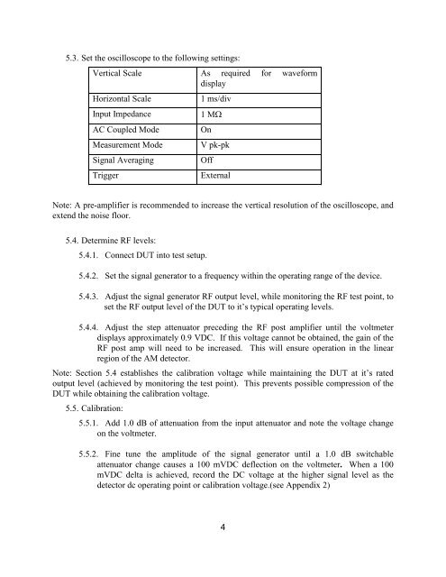
5.3. Set the oscilloscope to the following settings:<br />
Vertical Scale As required <strong>for</strong> wave<strong>for</strong>m<br />
display<br />
Horizontal Scale<br />
Input Impedance<br />
AC Coupled Mode<br />
Measurement Mode<br />
Signal Averaging<br />
Trigger<br />
1 ms/div<br />
1 MΩ<br />
On<br />
V pk-pk<br />
Off<br />
External<br />
Note: A pre-amplifier is recommended to increase the vertical resolution of the oscilloscope, and<br />
extend the noise floor.<br />
5.4. Determine RF levels:<br />
5.4.1. Connect DUT into test setup.<br />
5.4.2. Set the signal generator to a frequency within the operating range of the device.<br />
5.4.3. Adjust the signal generator RF output level, while monitoring the RF test point, to<br />
set the RF output level of the DUT to it’s typical operating levels.<br />
5.4.4. Adjust the step attenuator preceding the RF post amplifier until the voltmeter<br />
displays approximately 0.9 VDC. If this voltage cannot be obtained, the gain of the<br />
RF post amp will need to be increased. This will ensure operation in the linear<br />
region of the AM detector.<br />
Note: Section 5.4 establishes the calibration voltage while maintaining the DUT at it’s rated<br />
output level (achieved by monitoring the test point). This prevents possible compression of the<br />
DUT while obtaining the calibration voltage.<br />
5.5. Calibration:<br />
5.5.1. Add 1.0 dB of attenuation from the input attenuator and note the voltage change<br />
on the voltmeter.<br />
5.5.2. Fine tune the amplitude of the signal generator until a 1.0 dB switchable<br />
attenuator change causes a 100 mVDC deflection on the voltmeter. When a 100<br />
mVDC delta is achieved, record the DC voltage at the higher signal level as the<br />
detector dc operating point or calibration voltage.(see Appendix 2)<br />
4