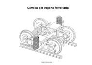
singularities and mobility of a class of 4-dof mechanisms
singularities and mobility of a class of 4-dof mechanisms
singularities and mobility of a class of 4-dof mechanisms

Create successful ePaper yourself
Turn your PDF publications into a flip-book with our unique Google optimized e-Paper software.
SINGULARITIES AND MOBILITY OF<br />
A CLASS OF 4-DOF MECHANISMS<br />
Dimiter Zlatanov 1 , Matteo Zoppi 2 <strong>and</strong> Clément M. Gosselin 3<br />
1 Universität Innsbruck, Technikerstr. 13, A-6020, Innsbruck, Austria<br />
2 Università di Genova, via Opera Pia 15A, 16145, Genova, Italia<br />
3 Laboratoire de robotique, Université Laval, Québec, Canada, G1K 7P4<br />
[zlatanov, gosselin]@gmc.ulaval.ca, zoppi@dimec.unige.it<br />
Abstract<br />
The paper discusses <strong>mobility</strong> <strong>and</strong> <strong>singularities</strong> <strong>of</strong> a <strong>class</strong> <strong>of</strong> 4-d<strong>of</strong> parallel<br />
wrists with four legs. The singular configurations are <strong>class</strong>ified in detail<br />
<strong>and</strong> their geometric interpretation is discussed. The velocity kinematics<br />
<strong>and</strong> the Jacobian operator are formulated via a screw-system approach.<br />
A fully parameterized package <strong>of</strong> Maple tools was developed <strong>and</strong> used<br />
to visualize <strong>singularities</strong> <strong>and</strong> their consequences.<br />
Keywords: <strong>singularities</strong>, 4d<strong>of</strong> <strong>mechanisms</strong><br />
1. Introduction<br />
The paper studies the <strong>mobility</strong> <strong>and</strong> <strong>singularities</strong> <strong>of</strong> a <strong>class</strong> <strong>of</strong> parallel<br />
<strong>mechanisms</strong> (PMs), Figure 1. When first introduced (Zlatanov <strong>and</strong> Gosselin,<br />
2001) these were the only known fully-parallel 4-d<strong>of</strong> chains. Later,<br />
other 4-d<strong>of</strong> PMs have been presented (Huang <strong>and</strong> Li, 2002).<br />
Four 5R legs, labelled A, . . .,D, connect base <strong>and</strong> platform. Consider<br />
leg L, L ∈ {A, B, C, D}. The joint screws (<strong>and</strong> their axes), ξ L 1 , . . .,ξ L 5 ,<br />
as well as their direction vectors, k L 1 , . . .,kL 5 , are numbered from the<br />
D<br />
C<br />
B<br />
ξ L 5<br />
O<br />
A<br />
π<br />
45<br />
L<br />
O<br />
π 0<br />
ξ L 4<br />
ξ L 3<br />
ξ L 45<br />
ξ L 2<br />
ξ L 1<br />
(a)<br />
(b)<br />
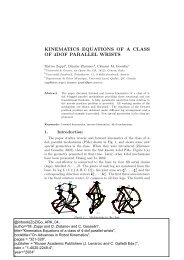
Figure 1.<br />
The mechanism architecture with 4-d<strong>of</strong>.
ase. The first three axes intersect in O, the fixed rotation centre <strong>of</strong> the<br />
PM, common to all legs. The fourth <strong>and</strong> fifth are parallel. The fifth<br />
axes, ξ A 5 , . . .,ξ D 5 , are parallel to a common platform plane, π h (fixed in<br />
the platform), but are not all parallel to each other. Then, the platform<br />
has four d<strong>of</strong>: it rotates arbitrarily around O <strong>and</strong> translates orthogonally<br />
to π h . The extrusion (heave), h, <strong>of</strong> the platform is the distance between<br />
π h <strong>and</strong> its parallel 0-extrusion plane, π 0 , through O.<br />
Singularities are <strong>class</strong>ified using six types, as in Zlatanov et al., 1995:<br />
redundant input/output (RI/RO), impossible output/input (IO/II), redundant<br />
passive motion (RPM), increased instantaneous <strong>mobility</strong> (IIM).<br />
A fully parametric mathematical model <strong>of</strong> the mechanism kinematics<br />
has been developed in Maple to support the analysis <strong>and</strong> illustrate <strong>and</strong><br />
verify the obtained conditions for singularity. The created library <strong>of</strong><br />
graphical <strong>and</strong> computational tools simplifies the analysis <strong>and</strong> provides a<br />
sophisticated <strong>and</strong> effective graphic output. All presented 3D figures have<br />
been automatically generated by Maple <strong>and</strong> are exact. The images can<br />
be modified immediately for different values <strong>of</strong> the geometric parameters.<br />
2. Analysis <strong>of</strong> the platform constraint<br />
We use the rotating reference frame Oijk with a fixed origin <strong>and</strong><br />
vectors constant in the platform, k ⊥ π 0 . For any frame, we associate<br />
a st<strong>and</strong>ard basis, {ϱ x , ϱ y , ϱ z , τ x , τ y , τ z }, <strong>of</strong> the space <strong>of</strong> twists, S. The<br />
basis elements are the three rotations <strong>and</strong> three translations about the<br />
coordinate axes. The dual wrench basis is {ϕ x , ϕ y , ϕ z , µ x , µ y , µ z }.<br />
For leg L, the twist systems T L ⊂ P L are spanned by all joint screws<br />
<strong>and</strong> by the passive (non-actuated) joint screws, respectively. The reciprocal<br />
system W L = TL<br />
⊥ consists <strong>of</strong> the platform wrenches the leg can<br />
resist (transmit to the base) when all its joints are free to move. The<br />
wrenches resisted when the actuated joint is locked form V L = PL ⊥.<br />
For any nonsingular leg posture (with linearly independent leg joint<br />
screws) Span (ϕ L 0<br />
) = W L V L , dim V L = 2, where ϕ L 0<br />
is the force at O<br />
with direction k L 5 (kL 4 ). In any leg singularity, Span (ϕL 0<br />
) W L ⊂ V L .<br />
The spaces <strong>of</strong> structural constraints, W = ∑ L W L, <strong>and</strong> actuated constraints,<br />
V = ∑ L V L, represent the wrenches the PM can resist, when the<br />
actuated joints are free <strong>and</strong> blocked, respectively. If no leg is singular,<br />
W = Span (ϕ A 0<br />
, . . .,ϕ D 0<br />
) = Span (ϕ x , ϕ y ). (Since k A 5 , . . .,kD 5 , are coplanar<br />
<strong>and</strong> not all parallel, the four ϕ L 0<br />
span the planar pencil <strong>of</strong> forces,<br />
W 0 = Span (ϕ x , ϕ y ), at O in π o . The PM cannot have a constraint<br />
singularity (Zlatanov et al., 2002), where dim W > 2.)<br />
With no leg singular, the platform freedoms, T = ∩ L T L = W ⊥ , are<br />
given by M = W ⊥ 0<br />
= Span (ϱ x , ϱ y , ϱ z , τ z ) (M ∗ = Span (ϕ z , µ x , µ y , µ z )
{e ∉ B <strong>and</strong> π L 45 ≢ π0} O ∉ πL 45 {e ∈ B or π L 45 ≡ π0} O ∈ πL 45<br />
π L 45<br />
ϕ L<br />
π L 45<br />
µ L<br />
ϕ L ⊥<br />
π L 45<br />
O<br />
ϕ L ⊥<br />
π<br />
45<br />
L<br />
π<br />
23<br />
L<br />
µ L<br />
(1)<br />
π L 23<br />
O ϕ L 0<br />
(2)<br />
π L 23<br />
O ϕ L 0<br />
(3)<br />
π L 23<br />
ϕ L 0<br />
(4)<br />
O ϕ L 0<br />
k L 1 ∦πL 23 k L 1 ‖πL 23 k L 1 ∦πL 23 k L 1 ‖πL 23<br />
Figure 2.<br />
Wrench spaces <strong>and</strong> leg geometry for each posture <strong>class</strong>.<br />
is the dual). In IO-type <strong>singularities</strong> T is smaller. A leg singularity leads<br />
to a loss <strong>of</strong> a platform freedom (IO) only if W L − W 0 ≠ ∅ (W L ⊄ W 0 ).<br />
Depending on the relative location <strong>of</strong> the passive joints in a leg, we distinguish<br />
four basic <strong>class</strong>es <strong>of</strong> leg postures, i.e. subsets, C L i , i = 1, . . .,4,<br />
<strong>of</strong> the feasible leg configuration space, C L . To describe geometrically a<br />
leg posture, q L , we refer to two planes: π23 L through ξL 2 <strong>and</strong> ξ L 3 ; <strong>and</strong> π45<br />
L<br />
defined by ξ L 4 <strong>and</strong> ξ L 5 . The link angle αi L i+1 , i < 3, is between kL i <strong>and</strong><br />
k L i+1 , while αL 34 is between kL 3 <strong>and</strong> the plane defined by ξL 4 <strong>and</strong> O.<br />
For each <strong>class</strong>, C L i , a sub<strong>class</strong>, C L i1, is defined by the additional condition<br />
k L 1 ‖ πL 23 (i.e., when the first three joint axes are coplanar).<br />
Class 1. C L 1 = {q L | k L 4 ∦ πL 23 <strong>and</strong> O ∉ πL 45 } (Figure 2–1).<br />
V L = Span (ϕ L 0<br />
, ϕ L ), where ϕ L is the force along π23 L ∩ πL 45 . The force<br />
ϕ L is not through O <strong>and</strong> not on π 0 , therefore the intersection V L ∩W 0 =<br />
Span (ϕ L 0<br />
), <strong>and</strong> V L is a cylindroid. Since O ∉ π45 L , then πL 45 ≢ π 0. If<br />
q L ∈ C L 11 (k L 1 ‖ πL 23 ), W L = V L <strong>and</strong> W L ⊄ W 0 , else W L = Span (ϕ L 0<br />
).<br />
Class 2. C L 2 = {q L | k L 4 ‖ πL 23 <strong>and</strong> O ∉ πL 45 } (Figure 2–2).<br />
V L = Span (ϕ L 0<br />
, µ L ) is the 2-system <strong>of</strong> the pure forces parallel to k L 4 <strong>and</strong><br />
lying on π23 L (µL is a pure moment orthogonal to π23 L ). We note that<br />
V L ∩ W 0 = Span (ϕ L 0<br />
). Since O ∉ π45 L , πL 45 ≢π 0. W L =V L <strong>and</strong> W L ⊄ W 0<br />
iff q L ∈ C L 21 (k L 1 ‖ πL 23 ), else W L = Span (ϕ L 0<br />
).<br />
Class 3. C L 3 = {q L | k L 4 ∦ πL 23 <strong>and</strong> O ∈πL 45 } (Figure 2–3).<br />
V L = Span (ϕ L 0<br />
, ϕ L ⊥<br />
) is the planar pencil <strong>of</strong> forces centred at O <strong>and</strong> lying<br />
in π45 L . ϕL ⊥ is a pure force through O orthogonal to kL 4 <strong>and</strong> lying on<br />
π45 L . If πL 45 ≡ π 0, then V L =W 0 ; else, V L ∩ W 0 = Span (ϕ L 0<br />
). W L =V L<br />
everywhere in C L 3 . Iff π45 L ≢π 0, W L ⊄ W 0 .<br />
Class 4. C L 4 = {q L | k L 4 ‖ πL 23 <strong>and</strong> O ∈πL 45 } (Figure 2–4).<br />
V L = Span (ϕ L 0<br />
, µ L , ϕ L ⊥<br />
) is a 3-system spanned by a planar pencil in<br />
π45 L <strong>and</strong> a moment perpendicular to πL 23 . (If αL 34 ≠ 0, then πL 23 ≢ πL 45<br />
<strong>and</strong> V L has screws <strong>of</strong> all pitches. Else, if α34 L = 0, then πL 23 ≡ πL 45<br />
<strong>and</strong> V L is spanned by the pure forces in a plane.) If π45 L ≡ π 0, then<br />
W 0 ⊂ V L ; else V L ∩ W 0 = Span (ϕ L 0<br />
). W L =V L if q L ∈ C L 41 (k L 1 ‖ πL 23 ),
k<br />
✛ rL 4<br />
✛l L 45✲<br />
✛<br />
r L 5<br />
✲<br />
✲<br />
♣ O<br />
ξ 3<br />
(a)<br />
O<br />
h<br />
(b)<br />
(c)<br />
Figure 3. (a) The heave section <strong>of</strong> leg L. (b) Fixed platform <strong>and</strong> moving base at<br />
maximum heave. (c) A leg allowing π45 L ≡π 0.<br />
else W L = Span (ϕ L 0<br />
, ϕ L ⊥ ). In CL 4 , we have extra constraints, W L ⊄ W 0 ,<br />
unless both π L 45 ≡π 0 <strong>and</strong> k L 1 ∦ πL 23 .<br />
Note that a leg singularity always leads to extra structural constraints<br />
(<strong>and</strong> an IO singularity), W L − W 0 ≠ ∅, except if π L 45 ≡π 0 <strong>and</strong> q L ∉ C L 41.<br />
3. The workspace <strong>and</strong> its boundary<br />
Let X ⊂ SO(3)×R be the 4-dimensional workspace <strong>of</strong> the mechanism.<br />
The extrusion boundary, B ∂X, consists <strong>of</strong> all feasible platform<br />
poses, e = (R, h), where the heave, h, achieves an extremal value for<br />
some L. The PRRR planar loop in Figure 3(a) represents the heave<br />
section <strong>of</strong> the PM along one <strong>of</strong> the leg chains. Extremal extension occurs<br />
when O ∈ π 45 , so a platform pose is in B iff for at least one leg π45 L ≢π 0<br />
<strong>and</strong> O ∈π45 L (qL ∈ C L 3 ∪C L 4 ). Figure 3(b) shows a mechanism in different<br />
configurations, with extremal heave <strong>and</strong> different platform orientations.<br />
(A PM may not reach extremal values <strong>of</strong> h for some platform rotation.<br />
In fact, if α12 L <strong>and</strong> αL 23 are sufficiently small, B can be empty.)<br />
The remainder <strong>of</strong> the boundary, ∂X − B, consists <strong>of</strong> mechanism configurations<br />
where, at least in one leg k L 1 ‖πL 23 , i.e., qL ∈ C L 11 ∪ C L 21.<br />
It can be proven rigorously that every configuration with e ∈ ∂X<br />
is an IO-type singularity. Conversely, an IO-type singularity generally<br />
implies e ∈ ∂X, the only exception being configurations where ξ L 1 ≡ ξ L 3 .<br />
Thus, only if α12 L = αL 23 can there be IO <strong>singularities</strong> for e ∈ int (X).<br />
4. The equivalent mechanism <strong>and</strong> π L 45 ≡π 0<br />
If all π L 45 ≢ π 0, the PM is instantaneously equivalent to a simplified<br />
mechanism (Figure 1b). The fourth <strong>and</strong> fifth joints <strong>of</strong> each leg are replaced<br />
by a single revolute joint, ξ L 45, at the intersection <strong>of</strong> π L 45 <strong>and</strong> π 0.
η B<br />
B<br />
A<br />
ζ A<br />
D<br />
η D<br />
D<br />
C<br />
A<br />
B<br />
C<br />
(a)<br />
(b)<br />
(c)<br />
Figure 4. (a) An (IIM, RI, RO)-singularity with π45 D ≡ π 0; ζ D is through O on<br />
π 0. (b) An (RPM, IIM, IO, II)-singularity with two C 4 legs. (c) An (RPM, RI, IIM,<br />
IO)-singularity with e ∈ B, q A ∈ C A 4 , q C ∈ C C 1 , q L ∈ C L 11, L = B, D.<br />
(If π45 L ‖ π 0, the new joint is prismatic.) The new joint velocity is the<br />
sum <strong>of</strong> the velocities it replaces.<br />
When π45 L ≡π 0, there is no equivalence. This occurs when O ∈π45 L <strong>and</strong><br />
the distance, r5 L, from ξL 5 to Oz equals r4 L ±lL 45 , where rL 4 is between Oz<br />
<strong>and</strong> ξ L 4 , <strong>and</strong> l45 L is the length <strong>of</strong> the last leg link (Figure3c).<br />
Suppose π45 L ≡π 0, while the other legs are nonsingular. An IO occurs<br />
only if q L ∈ C L 41. Then, there is also RPM <strong>and</strong> RI. The 5 joints <strong>of</strong><br />
leg L span a 3-system <strong>and</strong> the platform has 3-d<strong>of</strong>. Therefore, the PM<br />
has 5-d<strong>of</strong> (like a closed loop with 8 joints spanning a 3 system) <strong>and</strong><br />
IIM is present. The configuration also belongs to both or neither <strong>of</strong><br />
types II <strong>and</strong> RO depending on the other 3 leg chains. (Indeed, replace<br />
leg L with a passive nonsingular leg with the same 3-d<strong>of</strong>. Then this<br />
equivalent PM can have only a singularity <strong>of</strong> <strong>class</strong> (RO, II).) Therefore,<br />
the configuration is either (RI, RPM, IO, IIM) or with all six types.<br />
Otherwise, if q L ∉ C L 41, although leg L is singular, the platform is<br />
constrained only by W 0 <strong>and</strong> dim T = 4 (no IO). Either q L ∈ C L 4 − C L 41<br />
<strong>and</strong> we have an RPM singularity, or q L ∈ C L 3 <strong>and</strong> there is RI. In either<br />
case, since there is no IO, there must be an IIM-type singularity. (This<br />
follows from the interdependence rules <strong>of</strong> the singularity types, Zlatanov<br />
et al., 1995.) Moreover, if q L ∈ C L 3 <strong>and</strong> there is no RPM, an RO-type<br />
singularity must be present as well. Thus we have at least (RPM, IIM)<br />
or (RI, RO, IIM) <strong>and</strong> each can be augmented with (RO, II) if the other<br />
three legs cooperate. Figure 4(a) shows an example <strong>of</strong> a singularity <strong>of</strong><br />
<strong>class</strong> (IIM, RI, RO). Thus, π45 L ≡π 0 allows the six singularity <strong>class</strong>es with<br />
IIM <strong>and</strong> without IO, impossible for “usual” PMs (Zlatanov et al., 1994).<br />
Below, we generally assume that no π45 L ≡π 0.
η B<br />
D<br />
C<br />
B<br />
v<br />
A<br />
B<br />
D<br />
η C<br />
C<br />
B<br />
η A<br />
A<br />
A<br />
(a)<br />
(b)<br />
η D<br />
(c)<br />
Figure 5. IIM-type singularity with e ∈ int(X) <strong>and</strong> ξ L 1 ≡ ξ L 3 , ∀L. In (b) the<br />
wrenches η L <strong>of</strong> (a) are drawn with the lengths <strong>of</strong> their pitches, to show the linear<br />
dependence. In (c) the moment components <strong>of</strong> all η L are coplanar.<br />
5. Leg Singularities<br />
5.1 RPM- <strong>and</strong> IIM-type <strong>singularities</strong><br />
An RPM-type singularity occurs iff a leg chain has a linear dependence<br />
<strong>of</strong> the passive joints screws, dim P L < 4, i.e., dim V L > 2. According to<br />
Section 2, this is equivalent to q L ∈ C L 4 for some L.<br />
Each C 4 leg has one passive d<strong>of</strong>, so the redundant passive freedoms<br />
<strong>of</strong> the mechanism are as many as the C 4 legs. Figure 4b represents a<br />
configuration with two RPM freedoms.<br />
Provided that all π45 L ≢π 0, a necessary condition for O ∈π45 L is e ∈ B.<br />
Therefore, under this hypothesis, all RPM-type singular configurations<br />
have an end-effector in B <strong>and</strong> the workspace interior int (X) is free <strong>of</strong><br />
them. (As we saw, if the geometry <strong>of</strong> some leg is such that π45 L ≡π 0, it<br />
is possible to have an RPM-type singularity <strong>and</strong> e ∈ int (X).)<br />
A method for the study <strong>of</strong> IIM-type <strong>singularities</strong> in certain parallel<br />
<strong>mechanisms</strong> is given in Zlatanov et al., 1994. The approach can be<br />
applied to the instantaneously equivalent PM. A necessary <strong>and</strong> sufficient<br />
condition for IIM is the existence <strong>of</strong> four linearly dependant wrenches,<br />
η A , . . .,η D , not all zero, such that η L ∈ W L ∩ M ∗ , ∀L.<br />
If π45 L ≢ π 0 <strong>and</strong> α12 L ≠ αL 23 for all L, the mechanism configuration<br />
has an end-effector in ∂X <strong>and</strong> int (X) is free from IIM-type singularity.<br />
Examples <strong>of</strong> IIM-type configurations are presented in Figures 4–5.
C<br />
D<br />
A<br />
C<br />
D<br />
A<br />
C<br />
B<br />
D<br />
A<br />
B<br />
D<br />
A<br />
(a)<br />
B<br />
B<br />
(b)<br />
(c)<br />
C<br />
(d)<br />
Figure 6. Singularities with IO <strong>and</strong> RI. (a) e ∈ B, q L ∈ C L 3 , L = A, C. (b)q C ∈ C C 4<br />
also RPM-type singular.(c)e ∈ ∂X − B, q A ∈ C A 11, q L ∈ C L 1 , L = B, C, D. (d)e ∈<br />
int (X), ξ C 1 ≡ ξ C 3 , q L ∈ C L 1 , L = A, B, D.<br />
5.2 Singularities on <strong>and</strong> <strong>of</strong>f B<br />
For configurations with e ∈ B, either q L ∈ C L 3 or q L ∈ C L 4 (π45 L ≢π 0)<br />
for some L. All these are IO-type <strong>singularities</strong> with respect to extrusion.<br />
If q L ∈ C L 4 an RPM-type singularity occurs. Else, if q L ∈ C L 3 , there is an<br />
RI-type singularity. If q L ∈ C L 41, both RI- <strong>and</strong> RPM-type are present.<br />
When e ∈ ∂X − B, q L ∈ C L 11 ∪ C L 21 for all legs. Assuming π45 L ≢ π 0,<br />
such a configuration is an (RI, IO) singularity. Iff α12 L = αL 23 , there are<br />
leg <strong>singularities</strong> with e ∈ int (X). They are (at least) in the IO <strong>and</strong> RI<br />
types, but never in RPM. Figure 6 shows <strong>singularities</strong> <strong>of</strong> <strong>class</strong> (RI, IO).<br />
6. Singular configurations with nonsingular legs<br />
The analysis in the previous sections shows that if no leg is singular,<br />
the only possible singularity <strong>class</strong> is (RO, II), Figure 7. When π45 L ≢π 0<br />
<strong>and</strong> α12 L ≠ αL 23 , “no singular legs” is equivalent to e ∈ int (X).<br />
By using the equivalent PM with 4R legs we obtain the 4×4 Jacobian:<br />
⎡<br />
− 1<br />
r 45n A A 23 · ⎤<br />
kA 4 | n A 23<br />
− 1<br />
r<br />
Z =<br />
45n B B 23 · kB 4 | n B 23<br />
⎢ − 1<br />
r<br />
⎣ 45n C C 23 · kC 4 | n C (1)<br />
23 ⎥<br />
− 1<br />
r45n D D 23 · ⎦<br />
kD 4 | n D 23<br />
The rows <strong>of</strong> Z represent wrenches in M ∗ . These can be transformed to<br />
an equivalent 4-element spanning system with three (or four) pure moments.<br />
The condition for singularity is obtained as a 3 × 3 determinant,<br />
<strong>and</strong> in case <strong>of</strong> singularity, the RO-motion screw is derived symbolically.
(a)<br />
ξ RO<br />
ξ RO<br />
(b)<br />
(c)<br />
Figure 7. (RO, II) <strong>singularities</strong>. (a) The RO motion , ξ RO<br />
(pitch −0.00104) <strong>and</strong> the<br />
forces ϕ L are shown. (b-c) ξ RO<br />
<strong>and</strong> the velocities at the platform points are shown.<br />
7. Conclusions<br />
The paper studies the possible singularity types <strong>of</strong> a family <strong>of</strong> 4-d<strong>of</strong><br />
parallel wrists. Under certain hypotheses, the RPM-, RI-, IO- <strong>and</strong> IIMtype<br />
<strong>singularities</strong> are restricted to the workspace boundary. The typical<br />
interior <strong>singularities</strong> <strong>of</strong> type (RO, II) are identified by checking a system<br />
<strong>of</strong> 4 wrenches. Under the most general assumptions, these PMs allow<br />
all 21 singularity <strong>class</strong>es, including those 6 not possible for <strong>class</strong>ic PMs.<br />
The method <strong>of</strong> analysis is general. A fully parametric 3D virtual<br />
mock-up <strong>of</strong> the mechanism, based on a strong mathematic model, has<br />
been implemented in Maple via a library <strong>of</strong> computational <strong>and</strong> graphical<br />
routines created to analyze the architecture, visualize the mechanism<br />
behaviour <strong>and</strong> verify the results <strong>of</strong> the singularity analysis. Since most<br />
such routines are general, they can be reused for different <strong>mechanisms</strong>.<br />
The s<strong>of</strong>tware is available from the authors.<br />
References<br />
Huang, Z., Li, Q.C., “On the Type Synthesis <strong>of</strong> Lower-Mobility Parallel Manipulators”.<br />
Proc. <strong>of</strong> the workshop Fundamental Issues <strong>and</strong> Future Research Directions<br />
for Parallel Mechanisms <strong>and</strong> Manipulators, Québec City, Québec, Canada, 2002.<br />
Zlatanov, D., Benhabib, B., Fenton, R.G., “Velocity <strong>and</strong> singularity analysis <strong>of</strong> Hybrid<br />
Chain Manipulators”. Proc. <strong>of</strong> the 23rd Biennial Mechaism Conference, DE-Vol.72,<br />
pp.467-476, 1994.<br />
Zlatanov, D., Benhabib, B.,Fenton, R.G., “A unifying framework for <strong>class</strong>ification<br />
<strong>and</strong> interpretation <strong>of</strong> mechanism <strong>singularities</strong>”. Trans. <strong>of</strong> the ASME Journal <strong>of</strong><br />
Mechanical Design, Vol. 117, pp. 566-572, December 1995.<br />
Zlatanov, D., Bonev, I., Gosselin, C., “Constraint Singularities <strong>of</strong> Parallel Mechanisms”.<br />
Proc. <strong>of</strong> the 2002 IEEE International Conference on Robotics <strong>and</strong> Automation,<br />
ICRA 2002, May 11-15, Washington, DC, USA, pp.496-502, 2002.<br />
Zlatanov, D., Gosselin, C., “A family <strong>of</strong> new parallel architectures with four degrees<br />
<strong>of</strong> freedom”. In F.C. Park C.C. <strong>and</strong> Iurascu, editor, Computational Kinematics,<br />
pp.57-66, Mai 2001