bosch/lucas-cav diesel rotary injection pump timing
bosch/lucas-cav diesel rotary injection pump timing
bosch/lucas-cav diesel rotary injection pump timing

Create successful ePaper yourself
Turn your PDF publications into a flip-book with our unique Google optimized e-Paper software.
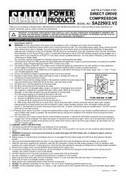
VS1131A<br />
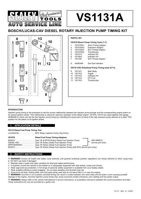
BOSCH/LUCAS-CAV DIESEL ROTARY INJECTION PUMP TIMING KIT<br />
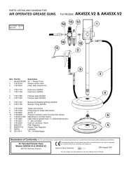
PARTS LIST<br />
VS1079 Bosch Pump Timing Tools (1-7).<br />
1 VS1079/01 Short Timing Adaptor<br />
2 VS1079/02 Extension Adaptor<br />
3 VS1079/03 M12 Thread Adaptor<br />
4 VS1079/04 Thumbscrew<br />
5 VS107/3 Indicator Pin<br />
6 VS108/3 Indicator Pin<br />
7 VS1259 M10 Thread Adaptor<br />
8 AK9634M Dial Test Indicator<br />
VS110 CAV/ Roto<strong>diesel</strong> Pump Timing tools (9-13).<br />
9 VS110/1 Main Body<br />
10 VS110/2 Toggle<br />
11 VS110/3 Indicator Pin<br />
12 VS110/4 DTI Foot<br />
13 VS110/5 Thumbscrew<br />
INTRODUCTION<br />
Injection <strong>pump</strong> <strong>timing</strong> is the procedure to set the correct relationship between the <strong>injection</strong> <strong>pump</strong> plunger and the corresponding engine piston on<br />
its upward ignition stroke. This relationship is critical for optimum operation of the <strong>diesel</strong> engine. VS1079, VS110 are used together with gauge<br />
AK9634M to check and set the fuel <strong>injection</strong> <strong>pump</strong> <strong>timing</strong> by indicating the exact point of travel of the high pressure <strong>pump</strong> element at a static TDC<br />
position for the piston on its ignition stroke.<br />
1. APPLICATION DETAILS<br />
VS110 Diesel Fuel Pump Timing Tool<br />
LUCAS/CAV . . . . . . . . . . . . . .DPC Rotary Injection Pump (Top Entry)<br />
VS1079<br />
Diesel Fuel Pump Timing Adaptors<br />
BOSCH . . . . . . . . . . . . . . . . . .Type VE & EPVE Rotary Diesel Fuel Injection Pump<br />
With M8/M12<br />
DIESEL KIKI . . . . . . . . . . . . . .Type VE Rotary Diesel Fuel Injection Pump<br />
service port entry<br />
NIPPONDENSO . . . . . . . . . . .Type VE Rotary Diesel Fuel Injection Pump<br />
BOSCH . . . . . . . . . . . . . . . . . .Type VE Rotary Diesel Fuel Injection Pump (with M10 service port entry)<br />
2. SAFETY INSTRUCTIONS<br />
p WARNING! Ensure all health and safety, local authority, and general workshop practice regulations are strictly adhered to when using tools.<br />
7 DO NOT use tools if damaged.<br />
3 Maintain tools in good and clean condition for best and safest performance.<br />
3 If required, ensure the vehicle to be worked on is adequately supported with axle stands, ramps and chocks.<br />
3 Wear approved eye protection. A full range of personal safety equipment is available from your Sealey dealer.<br />
3 Wear suitable clothing to avoid snagging. Do not wear jewellery and tie back long hair.<br />
3 Account for all tools, locking bolts, pins and parts being used and do not leave them in or near the engine.<br />
p WARNING! Incorrect or out of phase camshaft <strong>timing</strong> can result in contact between the valve head and the piston crown causing possible<br />
damage to the engine. Incorrect <strong>injection</strong> <strong>pump</strong> <strong>timing</strong> may cause excessive smoke emissions, poor starting and low power output.<br />
p WARNING! Always refer to the vehicle manufacturer’s service instructions, or proprietary manual to establish the current procedure and data.<br />
These instructions for use are provided as a guide only .<br />
VS1131 - 0869 - (2) - 200900
3. INSTRUCTIONS FOR USE<br />
3.1. VS1079 BOSCH INJECTION PUMPS.<br />
VS1079 Timing Adaptor Set connects to the service port of Bosch VE Rotary Injection Pumps to set the <strong>pump</strong> static<br />
<strong>timing</strong> position. VS1079/01 Adaptor can be used as a short reach adaptor extended by adding VS1079/02 according to<br />
access capability around the service port area. Its M8 thread screws directly into the service port or adaptor VS1079/03<br />
can be fitted to allow connection into M12 service ports or VS1259 for connection onto M10 service ports. VS1079 is used<br />
with AK9634M Dial Test Indicator.<br />
1. Locate service port, clean and remove the blanking plug.<br />
2. Unscrew plunger end off the DTI gauge and screw in its place VS108/3 Long or VS107/3 Short<br />
Indicator Pin whichever is appropriate to the configuration of <strong>timing</strong> adaptor being used, (short or<br />
extended). Ensure the indicator pin threads fully up to its shoulders into the DTI.<br />
3. Insert the dial test indicator into the <strong>timing</strong> adaptor and screw it into the service port of the <strong>pump</strong>.<br />
IMPORTANT: Ensure that the <strong>timing</strong> tool indicator pin can remain in constant contact with the<br />
<strong>injection</strong> <strong>pump</strong> plunger by pre-loading the dial test indicator with sufficient pre-load to cover the<br />
full travel of the <strong>pump</strong> plunger, plus 1mm. The pre-load is shown on minor scale of indicator gauge.<br />
4. Secure the DTI by clamping with VS1079/04 Thumbscrew.<br />
5. Turn the engine against the normal direction of rotation until the dial indicator needle reaches its Lowest Reading.<br />
6. Re-adjust the indicator gauge to ensure it has at least 1mm of pre-load and then zero the dial indicator gauge.<br />
7. Turn the engine in the normal direction of rotation to the static <strong>timing</strong> point and compare the dial test indicator reading against the<br />
manufacturer’s <strong>timing</strong> data, allowing for the pre-load.<br />
3.2. VS110 DIESEL INJECTION PUMP TIMING TOOL - CAV/ROTODIESEL DPC ROTARY INJECTION PUMP, TOP ENTRY.<br />
VS 110 is used for static <strong>timing</strong> of CAV/Roto<strong>diesel</strong> <strong>injection</strong> <strong>pump</strong>s after servicing operations which may have affected the <strong>timing</strong> e.g. removal<br />
of the <strong>timing</strong> belt or <strong>pump</strong>.<br />
3.2.1. Checking the Timing.<br />
1. Set the engine to TDC on No. 1 cylinder using the static <strong>timing</strong> points.<br />
2. Clean top of <strong>pump</strong>, remove cap from entry port, and insert Pin VS110/3 into hole (fig.1).<br />
3. Unscrew plunger end of AK9634M Dial Test Indicator and screw in its place Indicator Foot VS110/4. Ensure the foot threads fully up to its<br />
shoulder into the DTI, then locate and clamp body on <strong>pump</strong> spigot (fig.2).<br />
4. Fit Dial Test Indicator AK9634M against bell crank and pin VS110/3, and pre-load indicator gauge 1mm. Turn crankshaft 90 degrees<br />
anti-clockwise (opposite to normal rotation).<br />
5. Zero dial test indicator gauge.<br />
6. Turn crankshaft slowly in the normal direction of rotation to TDC and, if called for in service instructions, insert appropriate flywheel locking<br />
tool and/or <strong>injection</strong> <strong>pump</strong> pulley locking bolts.<br />
7. Check that the amount of lift on the indicator gauge corresponds to the figure stamped on the load lever plate (fig.3), or on side of <strong>pump</strong><br />
(each <strong>pump</strong> is calibrated and marked during manufacture), allowing for pre-load.<br />
3.2.2. Timing Adjustment.<br />
1. Set the engine to TDC on No.1 cylinder and, if called for in service instructions, fit flywheel locking pin, <strong>injection</strong> <strong>pump</strong> pulley bolts and/or<br />
camshaft pulley locking bolt.<br />
2. Ensure <strong>injection</strong> <strong>pump</strong> is in the fully retarded position (tilted away from the engine).<br />
3. Clean top of <strong>pump</strong>, remove cap from entry port (fig.1), and insert Pin VS110/3 into hole.<br />
4. Locate and clamp body VS110 on <strong>pump</strong> spigot (fig.2).<br />
5. Fit Dial Test Indicator AK9634M with Indicator Foot VS110/4 fitted against bell crank and pin VS110/3 and pre-load indicator gauge 1mm.<br />
6. Remove flywheel locking pin and pulley locking bolts (if previously fitted).<br />
7. Turn crankshaft 90 degrees anti-clockwise (opposite to normal rotation) and set the test indicator gauge dial to zero.<br />
8. Turn crankshaft slowly in the normal direction of rotation to TDC and, if called for in service instructions, insert appropriate flywheel locking<br />
tool and/or <strong>injection</strong> <strong>pump</strong> pulley locking bolts.<br />
9. Turn <strong>pump</strong> until dial test indicator reading corresponds to figure stamped on load lever plate (fig.3), or on side of <strong>pump</strong>, allowing for pre-load.<br />
10. Tighten <strong>pump</strong> retaining nuts and support bracket bolt to specified torque.<br />
11. Remove flywheel locking pin and pulley bolts (if previously fitted) and turn crankshaft two complete turns in normal direction of rotation.<br />
12. Refit appropriate locking pin/bolts.<br />
13. Dial test indicator should indicate specified figure +/- 0.04mm.<br />
IMPORTANT: Remove all locking pins and bolts.<br />
fig. 1 fig. 2 fig. 3