CATIA V5 Part Design
CATIA V5 Part Design
CATIA V5 Part Design

You also want an ePaper? Increase the reach of your titles
YUMPU automatically turns print PDFs into web optimized ePapers that Google loves.
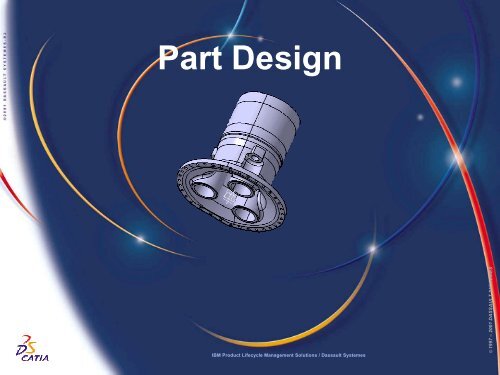
<strong>Part</strong> <strong>Design</strong><br />
IBM Product Lifecycle Management Solutions / Dassault Systemes<br />
Page 1<br />
© 1997 – 2001 DASSAULT SYSTEMES
Tutorial Objectives<br />
Description<br />
? This tutorial is an introduction to <strong>Part</strong> <strong>Design</strong>.<br />
Message<br />
? This tutorial illustrates how <strong>CATIA</strong> can<br />
?<strong>Design</strong> precise 3D mechanical parts with an intuitive and flexible user<br />
interface<br />
?Accommodate design requirements for parts of various complexitiesfrom<br />
simple to advanced<br />
?Apply the combined power of feature-based design with the flexibility<br />
of a Boolean approach<br />
Duration<br />
? 45 minutes<br />
Product Coverage<br />
? <strong>Part</strong> <strong>Design</strong><br />
IBM Product Lifecycle Management Solutions / Dassault Systemes<br />
Page 2<br />
© 1997 – 2001 DASSAULT SYSTEMES
Scenario Major Steps<br />
Here are the major steps of the scenario:<br />
Step 1<br />
? Add a new <strong>Part</strong> body<br />
Step 2<br />
?Create a Shaft feature<br />
Step 3<br />
? Create a Tap<br />
Step 4<br />
? Create a Circular Pattern<br />
Step 5<br />
? Create a Union Trim<br />
Step 6<br />
? Create an Edge Fillet feature<br />
Step 7<br />
? Create a Pad feature<br />
Step 8<br />
? Create a Hole feature<br />
Step 9<br />
? Thread / Tap Analysis<br />
IBM Product Lifecycle Management Solutions / Dassault Systemes<br />
Page 3<br />
© 1997 – 2001 DASSAULT SYSTEMES
Settings 1/2<br />
Depending on your needs, you may have to modify the <strong>CATIA</strong> <strong>V5</strong> settings (units, default<br />
directory, visualisation parameters, etc…)<br />
In order to use the appropriate settings for this tutorial, you have two possibilities:<br />
1. Do the following operations (simplest one):<br />
?BEFORE STARTING YOUR <strong>CATIA</strong> <strong>V5</strong> SESSION:<br />
? Copy or replace the directory ..\<strong>Part</strong> <strong>Design</strong>\Data\CATSettings in:<br />
For NT users<br />
For Windows 2000<br />
or XP users<br />
For Windows<br />
98 users<br />
C:\Winnt\Profiles\XXXXX\Application Data\DassaultSystemes<br />
C:\Documents and settings\Profiles\XXXXX\Application Data\DassaultSystemes<br />
C:\Windows\Profiles\XXXXX\Application Data\DassaultSystemes<br />
XXXX is the name used to log on to your computer<br />
? Do not forget to put this folder (CATSettings) in read mode:<br />
? Select the folder (CATSettings)<br />
? Click mouse button 3 then click on Properties and<br />
uncheck the Read-only Attribute<br />
? Select all the files in the folder<br />
? Click mouse button 3 then click on Properties and uncheck the Read-only<br />
Attribute<br />
2. Set them manually:<br />
? Launch your <strong>CATIA</strong> <strong>V5</strong> session and do the operations from page 40 onwards<br />
IBM Product Lifecycle Management Solutions / Dassault Systemes<br />
Page 4<br />
© 1997 – 2001 DASSAULT SYSTEMES
Settings 2/2<br />
For this tutorial you also need to install a material catalogue:<br />
? Do not do this step if you have already done it in getting started or in a previous tutorial<br />
? Copy the ..\Getting Started\Catalog.CATMaterial file under ..\Program<br />
Files\Dassault Systemes\M07\intel_a\startup\materials\French directory<br />
? Copy the ..\Getting Started\Catalog.CATMaterial file under ..\Program<br />
Files\Dassault Systemes\M07\intel_a\startup\materials\German directory<br />
? Copy the ..\Getting Started\Catalog.CATMaterial file under ..\Program<br />
Files\Dassault Systemes\M07\intel_a\startup\materials\Japanese directory<br />
? Copy the ..\Getting Started\Catalog.CATMaterial file under ..\Program<br />
Files\Dassault Systemes\M07\intel_a\startup\materials directory<br />
? Answer Yes in order to replace the old catalogue<br />
You are now ready to launch your <strong>CATIA</strong> <strong>V5</strong> session<br />
IBM Product Lifecycle Management Solutions / Dassault Systemes<br />
Page 5<br />
© 1997 – 2001 DASSAULT SYSTEMES
Step 1: Read the CAT<strong>Part</strong><br />
? You are going to read a <strong>CATIA</strong> <strong>V5</strong> document<br />
?Click file on the menu bar<br />
?Select open<br />
?The file selection definition box should appear<br />
?Select Spindle_start.CAT<strong>Part</strong> in the<br />
…\<strong>Part</strong> <strong>Design</strong>\Data\ directory where you<br />
installed the scenarios data<br />
?Click Open to confirm the selection<br />
?Answer Yes to the question because some<br />
libraries are not installed in this demonstration<br />
mode<br />
?Maximise the window<br />
IBM Product Lifecycle Management Solutions / Dassault Systemes<br />
Page 6<br />
© 1997 – 2001 DASSAULT SYSTEMES
Step 1: Add a new <strong>Part</strong> Body<br />
? You are going to add a new <strong>Part</strong> Body to allow<br />
Boolean operations<br />
?Reduce the Spindle Body tree by clicking on<br />
the (+) sign<br />
?Right click on Spindle Body<br />
?Select Define In Work Object<br />
?The Spindle Body should now be underlined in the<br />
specification tree to indicate that it is the “In Work<br />
Object”<br />
?Click on Insert on the menu bar<br />
?Select Body<br />
?Body.2 appears in the specification tree and is now<br />
the “in work” body<br />
IBM Product Lifecycle Management Solutions / Dassault Systemes<br />
Page 7<br />
© 1997 – 2001 DASSAULT SYSTEMES
Step 1: Rename the new <strong>Part</strong> Body<br />
? You will learn how to rename a <strong>Part</strong><br />
Body<br />
?Right click on Body.2 to display the<br />
contextual menu<br />
?Select Properties<br />
?The Properties dialog box will appear<br />
?Select Feature Properties tab<br />
? Change the name from Body.2 to<br />
Turret Body<br />
?Click OK to confirm the change<br />
?Turret Body will now be visible in the<br />
specification tree<br />
?You can compress the tree by<br />
clicking on the minus symbol if you’ve<br />
not already done so<br />
IBM Product Lifecycle Management Solutions / Dassault Systemes<br />
Page 8<br />
© 1997 – 2001 DASSAULT SYSTEMES
Step 2: Create a Shaft feature<br />
START POINT<br />
? You are going to draw a sketch and use it to create a<br />
Shaft<br />
? Click on yz plane in the specification tree<br />
? Click on the sketcher icon<br />
? Deactivate the Snap to Point capability by<br />
clicking on the icon (it must not be red)<br />
1<br />
? Click on the profile icon to create the white profile<br />
as shown on the right<br />
? Single-click at the indicated START point and<br />
move cursor down creating a vertical line (1)<br />
? The sketcher assistant tells you when the line is<br />
vertical with the blue colour line<br />
START POINT<br />
END<br />
POINT<br />
? Single click to stop your first line (2)<br />
? Move the cursor left to continue your profile with a<br />
horizontal line<br />
? The sketcher assistant tells you when the line is<br />
horizontal with the blue colour line<br />
? Single click to stop your second line (3)<br />
If you fail to create the sketch go to page 14<br />
3<br />
IBM Product Lifecycle Management Solutions / Dassault Systemes<br />
2<br />
Page 9<br />
© 1997 – 2001 DASSAULT SYSTEMES
Step 2: Create a Shaft feature<br />
START<br />
POINT<br />
END<br />
POINT<br />
?Move the cursor down to continue your<br />
profile with a vertical line<br />
? The sketcher assistant tells you when the line<br />
is vertical with the blue colour line<br />
?Single click to stop your third line (4)<br />
?Move the cursor right to continue your profile<br />
with a horizontal line<br />
? The sketcher assistant tells you when the line<br />
is horizontal with the blue colour line<br />
?Single click to stop your fourth line (5)<br />
6<br />
4<br />
5<br />
7<br />
?Move the cursor down to continue your<br />
profile with a vertical line<br />
? The sketcher assistant tells you when the line<br />
is vertical with the blue colour line<br />
?Single click to stop your fifth line (6)<br />
?Continue the profile until the END point<br />
checking the horizontal and vertical constraints<br />
(blue lines)<br />
IBM Product Lifecycle Management Solutions / Dassault Systemes<br />
Page 10<br />
© 1997 – 2001 DASSAULT SYSTEMES
Step 2: Create a Shaft feature<br />
END<br />
POINT<br />
?Single click at the “END POINT” to<br />
finish the profile and click on the<br />
Profile icon again to exit the function<br />
? Be sure that all geometrical<br />
constraints shown on the right are<br />
visible on the profile<br />
? If one or more geometrical<br />
constraints are missing, follow the<br />
following steps to add the constraint(s)<br />
?Select the line<br />
?Click on Constraints Defined in a<br />
Dialog Box icon<br />
?In the Constraint Definition<br />
window, click on Vertical or<br />
Horizontal box option<br />
?Click OK to confirm selection<br />
? Repeat the same procedure for<br />
any other missing geometrical<br />
constraint(s)<br />
IBM Product Lifecycle Management Solutions / Dassault Systemes<br />
Page 11<br />
© 1997 – 2001 DASSAULT SYSTEMES
Step 2: Create a Shaft feature<br />
?Click on the Corner icon<br />
?Select the two indicated lines<br />
? An arc and and its radius are displayed<br />
?Take care to have the pre-visualisation arc at the<br />
correct location (as shown) before pressing “Enter”<br />
?Enter “38” and the value will be<br />
automatically placed in the Radius field - then<br />
press “Enter”<br />
?Click on the Corner icon<br />
?Select the two indicated lines<br />
? An arc and and its radius are displayed<br />
?Enter 152 and the value will be<br />
automatically placed in the Radius field - then<br />
press “Enter”<br />
?Take care to have the pre-visualisation arc on the<br />
right location (as shown) before pressing “Enter”<br />
? You should have this result<br />
IBM Product Lifecycle Management Solutions / Dassault Systemes<br />
Page 12<br />
© 1997 – 2001 DASSAULT SYSTEMES
Step 2: Create a Shaft feature<br />
1<br />
Axis START<br />
POINT 2<br />
? Create an axis<br />
? Click on the axis icon to add an axis as<br />
shown on the right<br />
?Click in the “1” area. Make sure the line is<br />
blue<br />
?Click in the “2” area<br />
? Add a coincidence constraint between the axis<br />
and START and END points of the sketched axis<br />
line<br />
? Click on the axis<br />
?Press key to multi-select<br />
elements<br />
? Click on the START point<br />
? Click on Constraints Defined in a<br />
Dialog Box icon<br />
?The constraint definition box should<br />
appear<br />
? Check Coincidence box<br />
? Click OK to confirm selection<br />
? Repeat the same procedure for the axis and<br />
the END point of the sketched axis line<br />
IBM Product Lifecycle Management Solutions / Dassault Systemes<br />
COINCIDENCE<br />
CONSTRAINTS<br />
Page 13<br />
© 1997 – 2001 DASSAULT SYSTEMES
Step 2: Create a Shaft feature<br />
? You will add other dimensional<br />
constraints to the sketched profile as<br />
shown on the right<br />
?Click on the Constraint icon<br />
?Select the two indicated lines<br />
?Click on the area where you want<br />
to place the dimension<br />
?Double click on this dimension to<br />
edit it<br />
?Enter “110” in the Value field and<br />
press key<br />
?Repeat these operations to create<br />
the result as shown in the picture<br />
? Remember: to keep an icon active,<br />
you can double-click on it instead of<br />
clicking…<br />
? To create the “75” dimension you<br />
need to select an edge from the 3D<br />
geometry<br />
IBM Product Lifecycle Management Solutions / Dassault Systemes<br />
Page 14<br />
© 1997 – 2001 DASSAULT SYSTEMES
Step 2: Create a Shaft feature<br />
? Modify dimensional constraints to match<br />
the illustration as shown on the right<br />
?Repeat these operations to create<br />
the result as shown in the picture<br />
? When you create the “47”<br />
dimension select the vertical line. Click<br />
on MB3 and select the Position<br />
Dimension option to place the<br />
dimension – this will prevent you from<br />
accidentally selecting the geometry<br />
and creating a wrong dimension.<br />
? If you accidentally create a wrong<br />
dimension, you can restart by clicking<br />
on the Select icon<br />
?Click the Exit Workbench icon<br />
IBM Product Lifecycle Management Solutions / Dassault Systemes<br />
Page 15<br />
© 1997 – 2001 DASSAULT SYSTEMES
Step 2: Create a Shaft feature<br />
? If you fail to create the sketch:<br />
?If you have not already exited the<br />
Sketcher, click on the Exit<br />
workbench icon<br />
?Delete the Sketch.20 you just have<br />
created with MB3 on Sketch.20 +<br />
Delete<br />
?Expand the Open_Body.1 by<br />
clicking on the “+” symbol<br />
?With MB3 on Sketch.20 select<br />
Hide/Show<br />
? If you have succeeded in creating the<br />
sketch, continue with the scenario on the<br />
next page<br />
IBM Product Lifecycle Management Solutions / Dassault Systemes<br />
Page 16<br />
© 1997 – 2001 DASSAULT SYSTEMES
Step 2: Create a shaft feature<br />
? You can now create the shaft feature<br />
?Click on the shaft icon<br />
?The shaft definition box should<br />
appear<br />
? Be sure the parameters in the<br />
definition box match the parameters<br />
shown on the right. Select the sketch<br />
you have just designed if necessary.<br />
?Click on Preview to preview shaft<br />
feature<br />
?Click OK to confirm shaft feature<br />
?The shaft feature is added to the<br />
specification tree<br />
IBM Product Lifecycle Management Solutions / Dassault Systemes<br />
Page 17<br />
© 1997 – 2001 DASSAULT SYSTEMES
Step 3: Create a Tap<br />
? We will add a tap at the end of the shaft<br />
?Click on the thread / tap icon<br />
?The thread / tap definition box should<br />
appear<br />
?Click on the cylinder surface<br />
?Click on the limit face<br />
? Be sure the parameters in the<br />
definition box match the parameters<br />
shown on the right. Select the sketch<br />
you have just designed if necessary.<br />
?Click on Preview<br />
? The result is highlighted<br />
?Click OK to confirm<br />
IBM Product Lifecycle Management Solutions / Dassault Systemes<br />
Page 18<br />
© 1997 – 2001 DASSAULT SYSTEMES
Step 4: Create a circular pattern<br />
? You can create a multi instantiation of the shaft<br />
and of the tap using the circular pattern icon<br />
? Holding the < Crtl > key, Click on Shat.2 and<br />
Thread.1 in the tree.<br />
? Click and keep MB1 on the black arrow at the<br />
bottom right of the Rectangular Pattern icon<br />
? Drag the mouse then release MB1 on the circular<br />
pattern icon<br />
?If you don’t see the icon, it means that the<br />
corresponding toolbar is hidden due to your display<br />
settings. To find it, drag and drop the empty area from the<br />
bottom right side to the centre of the 3D view. Repeat this<br />
operation until you find the right toolbar. To put it back, do<br />
the reverse operation<br />
?The circular pattern definition box should appear<br />
? Select Complete crown in the Parameters field<br />
? Enter 3 for the Instance(s) field<br />
? If not already done so.<br />
? Click on the Reference element field<br />
? Select the external cylinder in the 3D view<br />
? Click OK to confirm circular pattern of shaft<br />
IBM Product Lifecycle Management Solutions / Dassault Systemes<br />
Page 19<br />
© 1997 – 2001 DASSAULT SYSTEMES
Step 5: Create a union trim<br />
? You can use a Boolean operation to<br />
assemble and trim the two bodies<br />
?Right click on Turret Body in the<br />
specification tree<br />
?Select Turret Body object<br />
?Select Union Trim…<br />
?The trim definition box should appear<br />
IBM Product Lifecycle Management Solutions / Dassault Systemes<br />
Page 20<br />
© 1997 – 2001 DASSAULT SYSTEMES
Step 5: Create a union trim<br />
?Click on the Faces to remove field<br />
?Using the mouse, select the 3<br />
faces of the shaft on the geometry as<br />
shown on the right<br />
? The faces should turn pink<br />
?Click on the Faces to keep field<br />
?Using the mouse, select the lower<br />
band of the Spindle Body as shown<br />
on the right<br />
? The face should turn blue<br />
FACES TO REMOVE<br />
IBM Product Lifecycle Management Solutions / Dassault Systemes<br />
FACES TO KEEP<br />
Page 21<br />
© 1997 – 2001 DASSAULT SYSTEMES
Step 5: Create a union trim<br />
?Click Preview to preview union trim<br />
?Click OK to confirm union trim<br />
?Trim.1 is added to the specification<br />
tree<br />
IBM Product Lifecycle Management Solutions / Dassault Systemes<br />
Page 22<br />
© 1997 – 2001 DASSAULT SYSTEMES
Step 6: Create an edge fillet<br />
? You can now create an edge fillet<br />
?Click on the edge fillet icon<br />
? Key in 38mm for the radius field<br />
?Click on Object(s) to fillet field<br />
?Using the mouse,select the 3 inner<br />
edges of the shaft as shown below<br />
?Click OK to confirm edge fillet<br />
feature<br />
EDGE 1<br />
EDGE 3<br />
EDGE 2<br />
IBM Product Lifecycle Management Solutions / Dassault Systemes<br />
Page 23<br />
© 1997 – 2001 DASSAULT SYSTEMES
Step 7: Create a pad feature<br />
? You will create a pad feature, using the<br />
profile sketched on the surface, as shown<br />
on the right<br />
?Click on one of the 3 sketch<br />
surface as shown<br />
?Click on the Sketcher icon<br />
SKETCH SURFACE<br />
IBM Product Lifecycle Management Solutions / Dassault Systemes<br />
Page 24<br />
© 1997 – 2001 DASSAULT SYSTEMES
Step 7: Create a pad feature<br />
? Sketching the pad profile<br />
? Click on the project 3D elements icon<br />
? Select the edge you want to project, as<br />
shown on the right<br />
? Click anywhere off the geometry to<br />
confirm selection of edge<br />
?The colour of the edge should now be<br />
yellow<br />
? Click and hold MB1 on the black arrow at<br />
the bottom right of the Circle icon<br />
? Drag the mouse then release MB1 on the<br />
Arc icon<br />
EDGE TO PROJECT<br />
? Select the origin as the centre point of<br />
the arc<br />
?Make sure the Double circle appears.<br />
This means there will be a coincidence<br />
constraint between this point and the origin<br />
IBM Product Lifecycle Management Solutions / Dassault Systemes<br />
ARC CENTER<br />
POINT<br />
Page 25<br />
© 1997 – 2001 DASSAULT SYSTEMES
Step 7: Create a pad feature<br />
?Click on the start point and end point area<br />
of the arc as shown on the right<br />
START POINT<br />
END POINT<br />
? Connecting the start point of the arc with the<br />
endpoint of the projected edge as shown on the<br />
right<br />
?Click on the line icon<br />
?Select the start point of the arc<br />
?Here again, make sure a Double circle appears<br />
?Select the endpoint of the projected edge<br />
?Here again, make sure a Double circle appears<br />
?Click anywhere off the geometry to confirm<br />
creation of the line<br />
PROJECTED EDGE<br />
ENDPOINT<br />
IBM Product Lifecycle Management Solutions / Dassault Systemes<br />
Page 26<br />
© 1997 – 2001 DASSAULT SYSTEMES
Step 7: Create a pad feature<br />
? You will now duplicate an element using<br />
symmetry<br />
?Click on the Symmetry icon<br />
?Click on the line between the start<br />
point of the arc and the endpoint of<br />
the projected edge.<br />
LINE TO SYMMETRY<br />
SYMMETRICAL<br />
LINE<br />
?Click on the vertical axis. This is<br />
the line from which the element will<br />
remain equidistant<br />
?A line should appear between the<br />
endpoint of the arc and the endpoint of<br />
the projected edge as shown on the<br />
right<br />
?The symmetry symbol should appear<br />
as shown on the right<br />
VERTICAL AXIS<br />
IBM Product Lifecycle Management Solutions / Dassault Systemes<br />
Page 27<br />
© 1997 – 2001 DASSAULT SYSTEMES
Step 7: Create a pad feature<br />
? Adding a coincidence constraint<br />
between the endpoint of the arc and the<br />
endpoint of the symmetrical line as shown<br />
on the right. This will close the contour<br />
? One of the scenarios on the right<br />
should match what you have on your<br />
screen<br />
?Click on the endpoint of the arc<br />
?Hold control key to multi-select<br />
?Click on endpoint of the projected<br />
edge<br />
?Click on Constraints Defined in a<br />
Dialog Box icon<br />
?Check Coincidence box<br />
?Click OK to confirm selection<br />
? Of course, you could have created<br />
the second line with the same<br />
operations used for the first one: the<br />
above operation was just to<br />
demonstrate another functionality<br />
?Click on the Exit Workbench icon<br />
IBM Product Lifecycle Management Solutions / Dassault Systemes<br />
ARC ENDPOINT<br />
SYMMETRICAL<br />
LINE ENDPOINT<br />
Page 28<br />
© 1997 – 2001 DASSAULT SYSTEMES
Step 7: Create a pad feature<br />
?Click on Pad icon<br />
?The pad definition box should appear<br />
?Select the profile you have just<br />
created if needed<br />
?Click on the Reverse Direction<br />
button<br />
?Click on the Type field<br />
?Select Up to plane<br />
?Click on the Limit field<br />
LIMIT (Plane.1)<br />
?Using the mouse select Plane.1 in<br />
the 3D window as shown on the right<br />
IBM Product Lifecycle Management Solutions / Dassault Systemes<br />
Page 29<br />
© 1997 – 2001 DASSAULT SYSTEMES
Step 7: Create a pad feature<br />
?Click OK to confirm pad feature<br />
?Select View / Tree Expansion /<br />
Expand First Level<br />
IBM Product Lifecycle Management Solutions / Dassault Systemes<br />
Page 30<br />
© 1997 – 2001 DASSAULT SYSTEMES
Step 7: Create a circular pattern<br />
? Creating a multi instantiation of the pad<br />
using the circular pattern icon<br />
?Click on Pad.3 in the specification<br />
tree<br />
?Click on the Circular Pattern icon<br />
?The circular pattern definition box<br />
should appear<br />
?Select Complete crown in the<br />
Parameters field<br />
?Enter 3 in the Instance(s) field<br />
?Click on the Reference element<br />
field<br />
?Click on the external cylinder in the<br />
3D view<br />
?Click on Preview to preview<br />
circular pattern of pad<br />
?Click OK to confirm circular pattern<br />
of pad<br />
IBM Product Lifecycle Management Solutions / Dassault Systemes<br />
Page 31<br />
© 1997 – 2001 DASSAULT SYSTEMES
Step 8: Create a hole feature<br />
? You will use the drag and drop feature<br />
of <strong>V5</strong> to create a hole feature<br />
AREA FOR HOLE<br />
?Drag and drop the Hole icon<br />
?Make sure you keep MB1 pressed<br />
when using drag and drop feature<br />
?Release the icon on the surface<br />
where you want to create the hole, as<br />
shown on the right<br />
IBM Product Lifecycle Management Solutions / Dassault Systemes<br />
Page 32<br />
© 1997 – 2001 DASSAULT SYSTEMES
Step 8: Create a hole feature<br />
? Changing the extension type of the hole<br />
from Blind to Up To Plane<br />
?Click on pull down arrow and<br />
change setting from Blind to Up To<br />
Plane<br />
?Click on the Diameter field<br />
? Key in 120 mm<br />
?Click on Limit field<br />
?Select Plane.1 in the 3D window as<br />
shown on the right<br />
IBM Product Lifecycle Management Solutions / Dassault Systemes<br />
LIMIT (Plane.1)<br />
Page 33<br />
© 1997 – 2001 DASSAULT SYSTEMES
Step 8: Create a hole feature<br />
? You will now add a concentricity<br />
constraint between the hole and the inner<br />
hole of the shaft<br />
?Click on the Sketcher icon in the<br />
Hole Definition box<br />
? This automatically takes you into<br />
the sketcher workbench<br />
?Click on centre point of the hole as<br />
shown on the right<br />
?Hold control key to multi-select<br />
?Click on inner hole of the shaft as<br />
shown on the right<br />
? Click on Constraints Defined in a<br />
Dialog Box icon<br />
?Check Concentricity box<br />
?Click OK to confirm selection<br />
HOLE CENTRE POINT<br />
IBM Product Lifecycle Management Solutions / Dassault Systemes<br />
SHAFT INNER HOLE<br />
Page 34<br />
© 1997 – 2001 DASSAULT SYSTEMES
Step 8: Create a hole feature<br />
?Click on the Exit icon<br />
?Click on Preview to preview hole<br />
feature<br />
?Click OK to confirm hole feature<br />
IBM Product Lifecycle Management Solutions / Dassault Systemes<br />
Page 35<br />
© 1997 – 2001 DASSAULT SYSTEMES
Step 8: Create a circular pattern<br />
? Creating a circular pattern of the hole<br />
using the circular pattern icon<br />
?Click on the Circular Pattern icon<br />
?Click on Hole.6 in the specification<br />
tree<br />
?The circular pattern definition box<br />
should appear<br />
?Select Complete crown in the<br />
Parameters field<br />
?Enter 3 in the Instance(s) field<br />
?Click on the Reference element<br />
field<br />
?Click on the external cylinder in the<br />
3D view<br />
?Click on Preview to preview<br />
circular pattern of hole<br />
?Click OK to confirm circular pattern<br />
of hole<br />
IBM Product Lifecycle Management Solutions / Dassault Systemes<br />
Page 36<br />
© 1997 – 2001 DASSAULT SYSTEMES
Step 9 : Thread / Tap Analysis<br />
? Check every tap / thread realised in<br />
your part<br />
? Click on the Tap – Thread<br />
Analysis icon<br />
? As previously, if the icon is not<br />
visible, drag and drop the bottom<br />
right toolbars…<br />
? Switch off Show numerical value<br />
? All manufacturing is highlighted.<br />
? Click on Apply to show the threads<br />
and taps.<br />
?Click on Close to finish<br />
IBM Product Lifecycle Management Solutions / Dassault Systemes<br />
Page 37<br />
© 1997 – 2001 DASSAULT SYSTEMES
End of scenario<br />
? You now have the final part as shown<br />
on the right<br />
? CONGRATULATIONS<br />
IBM Product Lifecycle Management Solutions / Dassault Systemes<br />
Page 38<br />
© 1997 – 2001 DASSAULT SYSTEMES
Manual Settings<br />
IBM Product Lifecycle Management Solutions / Dassault Systemes<br />
Page 39<br />
© 1997 – 2001 DASSAULT SYSTEMES
Settings<br />
Tools/Options<br />
? We will configure the environment of<br />
<strong>CATIA</strong><br />
?Select Tools + Options menu<br />
? We will erase any previous<br />
configurations.<br />
?Click on General<br />
?Click on the Reset Bottom<br />
?Select for all the tabpages<br />
?Click YES<br />
IBM Product Lifecycle Management Solutions / Dassault Systemes<br />
Page 40<br />
© 1997 – 2001 DASSAULT SYSTEMES
Settings<br />
Tools/Options<br />
? Under General select Display on the<br />
tree<br />
?Check Fixed Size and enter 20 as<br />
value in the field.<br />
IBM Product Lifecycle Management Solutions / Dassault Systemes<br />
Page 41<br />
© 1997 – 2001 DASSAULT SYSTEMES
Congratulations<br />
IBM Product Lifecycle Management Solutions / Dassault Systemes<br />
Page 42<br />
© 1997 – 2001 DASSAULT SYSTEMES