ESWA Induced Draft Closed Circuit Fluid Coolers ... - EVAPCO.com.au
ESWA Induced Draft Closed Circuit Fluid Coolers ... - EVAPCO.com.au
ESWA Induced Draft Closed Circuit Fluid Coolers ... - EVAPCO.com.au

Create successful ePaper yourself
Turn your PDF publications into a flip-book with our unique Google optimized e-Paper software.
<strong>ESWA</strong> <strong>Closed</strong> <strong>Circuit</strong> <strong>Coolers</strong><br />
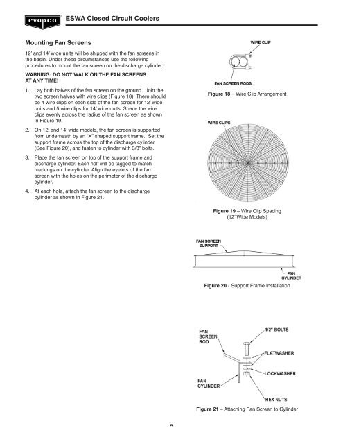
Mounting Fan Screens<br />
12’ and 14’ wide units will be shipped with the fan screens in<br />
the basin. Under these circumstances use the following<br />
procedures to mount the fan screen on the discharge cylinder.<br />
WARNING: DO NOT WALK ON THE FAN SCREENS<br />
AT ANY TIME!<br />
1. Lay both halves of the fan screen on the ground. Join the<br />
two screen halves with wire clips (Figure 18). There should<br />
be 4 wire clips on each side of the fan screen for 12’ wide<br />
units and 5 wire clips for 14’ wide units. Space the wire<br />
clips evenly across the radius of the fan screen as shown<br />
in Figure 19.<br />
2. On 12’ and 14’ wide models, the fan screen is supported<br />
from underneath by an “X” shaped support frame. Set the<br />
support frame across the top of the discharge cylinder<br />
(See Figure 20), and fasten to cylinder with 3/8” bolts.<br />
3. Place the fan screen on top of the support frame and<br />
discharge cylinder. Each half will be tagged to match<br />
markings on the cylinder. Align the eyelets of the fan<br />
screen with the holes on the perimeter of the discharge<br />
cylinder.<br />
4. At each hole, attach the fan screen to the discharge<br />
cylinder as shown in Figure 21.<br />
Figure 18 – Wire Clip Arrangement<br />
Figure 19 – Wire Clip Spacing<br />
(12’ Wide Models)<br />
Figure 20 - Support Frame Installation<br />
Figure 21 – Attaching Fan Screen to Cylinder<br />
8