For Evapco Fibreglass Cooling Towers, Closed ... - EVAPCO.com.au
For Evapco Fibreglass Cooling Towers, Closed ... - EVAPCO.com.au
For Evapco Fibreglass Cooling Towers, Closed ... - EVAPCO.com.au

You also want an ePaper? Increase the reach of your titles
YUMPU automatically turns print PDFs into web optimized ePapers that Google loves.
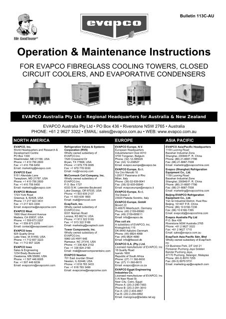
Bulletin 113C-AU<br />
Operation & Maintenance Instructions<br />
FOR <strong>EVAPCO</strong> FIBREGLASS COOLING TOWERS, CLOSED<br />
CIRCUIT COOLERS, AND EVAPORATIVE CONDENSERS<br />
<strong>EVAPCO</strong> Australia Pty Ltd – Regional Headquarters for Australia & New Zealand<br />
<strong>EVAPCO</strong> Australia Pty Ltd • PO Box 436 • Riverstone NSW 2765 • Australia<br />
PHONE: +61 2 9627 3322 • EMAIL: sales@evapco.<strong>com</strong>.<strong>au</strong> • WEB: www.evapco.<strong>com</strong>.<strong>au</strong><br />
NORTH AMERICA EUROPE ASIA PACIFIC<br />
<strong>EVAPCO</strong>, Inc.<br />
World Headquarters and Research &<br />
Development Centre<br />
PO Box 1300<br />
Westminster, MD 21158, USA<br />
Phone: +1 410 756 2600<br />
Fax: +1 410 756 6450<br />
Email: marketing@evapco.<strong>com</strong><br />
<strong>EVAPCO</strong> East<br />
5151 Allendale Lane<br />
Taneytown, MD 21787, USA<br />
Phone: +1 410 756 2600<br />
Fax: +1 410 756 6450<br />
Email: marketing@evapco.<strong>com</strong><br />
<strong>EVAPCO</strong> Midwest<br />
1723 York Road<br />
Greenup, IL 62428, USA<br />
Phone: +1 217 923 3431<br />
Fax: +1 217 923 3300<br />
Email: evap<strong>com</strong>w@evap<strong>com</strong>w.<strong>com</strong><br />
<strong>EVAPCO</strong> West<br />
1900 West Almond Avenue<br />
Madera, CA 93637, USA<br />
Phone: +1 559 673 2207<br />
Fax: +1 559 673 2378<br />
Email: contact@evapcowest.<strong>com</strong><br />
<strong>EVAPCO</strong> Iowa<br />
925 Quality Drive<br />
Lake View, IA 51450, USA<br />
Phone: +1 712 657 3223<br />
Fax: +1 712 657 3226<br />
<strong>EVAPCO</strong> Iowa<br />
Sales & Engineering<br />
1234 Brady Boulevard<br />
Owatonna, MN 55060, USA<br />
Phone: +1 507 446 8005<br />
Fax: +1 507 446 8239<br />
Email: evap<strong>com</strong>n@evap<strong>com</strong>n.<strong>com</strong><br />
Refrigeration Valves & Systems<br />
Corporation (RVS)<br />
Wholly owned subsidiary of<br />
<strong>EVAPCO</strong>,Inc.<br />
1520 Crosswind Dr<br />
Bryan, TX 77808, USA<br />
Phone: +1 979 778 0095<br />
Fax: +1 979 778 0030<br />
Email: rvs@rvscorp.<strong>com</strong><br />
McCormack Coil Company, Inc.<br />
Wholly owned subsidiary of<br />
<strong>EVAPCO</strong>,Inc.<br />
P.O. Box 1727<br />
6333 S.W. Lakeview Boulevard<br />
Lake Oswego, OR 97035, USA<br />
Phone: +1 503 639 2137<br />
Fax: +1 503 639 1800<br />
Email: mail@mmccoil.<strong>com</strong><br />
EvapTech, Inc.<br />
Wholly owned subsidiary of<br />
<strong>EVAPCO</strong>,Inc.<br />
8331 Nieman Road<br />
Lenexa, KS 66214, USA<br />
Phone: +1 913 322 5165<br />
Fax: +1 913 322 5166<br />
Email: marketing@evaptech.<strong>com</strong><br />
Tower Components, Inc.<br />
Wholly owned subsidiary of<br />
<strong>EVAPCO</strong>,Inc.<br />
5960 US HWY 64E<br />
Ramseur, NC 27316, USA<br />
Phone: +1 336 824 2102<br />
Fax: +1 336 824 2190<br />
Email: mail@tower<strong>com</strong>ponentsinc.<strong>com</strong><br />
<strong>EVAPCO</strong> Newton<br />
701 East Jourdan Street<br />
Newton, IL 62448, USA<br />
Phone: +1 618 783 3433<br />
Fax: +1 618 783 3499<br />
Email: evap<strong>com</strong>w@evap<strong>com</strong>w.<strong>com</strong><br />
<strong>EVAPCO</strong> Europe, N.V.<br />
European Headquarters<br />
Industrieterrein Oost 4010<br />
3700 Tongeren, Belgium<br />
Phone: (32) 12-395029<br />
Fax: (32) 12-238527<br />
Email: evapco.europe@evapco.be<br />
<strong>EVAPCO</strong> Europe, S.r.l.<br />
Via Ciro Menotti 10<br />
I-20017 Passirana di Rho<br />
Milan, Italy<br />
Phone: (39) 02-939-9041<br />
Fax: (39) 02-935-00840<br />
Email: evapcoeurope@evapco.it<br />
<strong>EVAPCO</strong> Europe, S.r.l.<br />
Via Dosso 2<br />
23020 Piateda Sondrio, Italy<br />
<strong>EVAPCO</strong> Europe, GmbH<br />
Bovert 22<br />
D-40670 Meerbusch, Germany<br />
Phone: (49) 2159-69560<br />
Fax: (49) 2159-695611<br />
Email: info@evapco.de<br />
Flex coil a/s<br />
A subsidiary of <strong>EVAPCO</strong>, Inc.<br />
Knøsgårdvej 115<br />
DK-9440 Aabybro Denmark<br />
Phone: (45) 9824 4999<br />
Fax: (45) 9824 4990<br />
Email: info@flexcoil.dk<br />
<strong>EVAPCO</strong> S.A. (Pty.) Ltd.<br />
Licensed manufacturer of <strong>EVAPCO</strong>, Inc<br />
18 Quality Road<br />
Isando 1600<br />
Republic of South Africa<br />
Phone: (27) 11 392-6630<br />
Fax: (27) 11-392-6615<br />
Email: evapco@icon.co.za<br />
<strong>EVAPCO</strong> Egypt Engineering<br />
Industries Co.<br />
Licensed manufacturer of <strong>EVAPCO</strong>, Inc<br />
5 Al Nasr Road St.<br />
Nasr City, Cairo, Egypt<br />
Phone A: (20) 2-290-7483<br />
Phone B: (20) 2-291-3610<br />
Fax A: (20) 2-404-4667<br />
Fax B: (20) 2-290-0892<br />
Email: manzgroup@tedata.net.eg<br />
<strong>EVAPCO</strong> Asia/Pacific Headquarters<br />
1159 Luoning Road<br />
Baoshan Industrial Zone<br />
Shanghai, 200949 P. R. China<br />
Phone: (86) 21-6687-7786<br />
Fax: (86) 21-6687-7008<br />
Email: marketing@evapcochina.<strong>com</strong><br />
<strong>Evapco</strong> (Shanghai) Refrigeration<br />
Equipment Co., Ltd.<br />
1159 Luoning Road<br />
Baoshan Industrial Zone<br />
Shanghai, 200949 P. R. China<br />
Phone: (86) 21-6687-7786<br />
Fax: (86) 21-6687-7008<br />
Email: marketing@evapcochina.<strong>com</strong><br />
Beijing <strong>EVAPCO</strong> Refrigeration<br />
Equipment Co., Ltd.<br />
Yan Qi Industrial District, Huai Rou<br />
Beijing, 101407 P.R. China<br />
Phone: (86) 10 6166-7238<br />
Fax: (86) 10 6166-7395<br />
Email: evapcobj@evapcochina.<strong>com</strong><br />
<strong>Evapco</strong> Australia Pty Ltd<br />
P.O. Box 436<br />
Riverstone NSW Australia 2765<br />
Phone: +61 2 9627 3322<br />
Fax: +61 2 9627 1715<br />
Email: sales@evapco.<strong>com</strong>.<strong>au</strong><br />
EvapTech Asia Pacific Sdn. Bhd<br />
Wholly owned subsidiary of EvapTech<br />
inc<br />
IOI Business Park, 2/F Unit 21<br />
Persiaran Puchong Jaya Selatan<br />
Bandar Puchong Jaya,<br />
47170 Puchong, Selangor, Malaysia<br />
Phone: (60-3) 8070 7255<br />
Fax: (60-3) 8070 5731<br />
Email: marketing-ap@evaptech.<strong>com</strong>
Operation and Maintenance Instructions<br />
Table of Contents<br />
Introduction ...................................................................................................................................................................... 5<br />
Safety Prec<strong>au</strong>tions ............................................................................................................................................................ 5<br />
Initial Storage and/or Idle Period Re<strong>com</strong>mendations ...................................................................................................... 6<br />
Initial and Seasonal Start-Up Checklist ............................................................................................................................. 7<br />
General .......................................................................................................................................................................... 7<br />
Before the unit has been energized, check the following: ........................................................................................... 7<br />
After the unit has been energized, check the following: .............................................................................................. 8<br />
Maintenance Checklist ...................................................................................................................................................... 9<br />
Seasonal Shut-Down Checklist ........................................................................................................................................ 10<br />
Basic <strong>Cooling</strong> Tower Sequence of Operation .................................................................................................................. 11<br />
System Off / No Load .................................................................................................................................................. 11<br />
System / Condensing Temperature Rises ................................................................................................................... 11<br />
System Temperature Stabilizes ................................................................................................................................... 11<br />
System Temperature Drops ........................................................................................................................................ 11<br />
System Off / No Load .................................................................................................................................................. 12<br />
Bypass Mode ............................................................................................................................................................... 12<br />
Optional Defrost Cycle ................................................................................................................................................ 12<br />
Basic <strong>Closed</strong> Circuit Cooler / Evaporative Condenser Sequence of Operation ............................................................... 12<br />
System Off / No Load .................................................................................................................................................. 12<br />
System / Condensing Temperature Rises ................................................................................................................... 12<br />
System Temperature Stabilizes ................................................................................................................................... 13<br />
System / Condensing Temperature Drops .................................................................................................................. 13<br />
System Off / No Load .................................................................................................................................................. 13<br />
Dry Operation ............................................................................................................................................................. 13<br />
Fan System ...................................................................................................................................................................... 13<br />
Fan Motor Bearings ..................................................................................................................................................... 13<br />
Fan Shaft Ball Bearings ................................................................................................................................................ 13<br />
Fan Shaft Sleeve Bearings ........................................................................................................................................... 14<br />
Fan Belt Adjustment .................................................................................................................................................... 15<br />
Gear Drives .................................................................................................................................................................. 17<br />
Air Inlet ........................................................................................................................................................................ 17<br />
Fan System Capacity Control .......................................................................................................................................... 17<br />
Fan Motor Cycling ....................................................................................................................................................... 17<br />
Two Speed Motors ...................................................................................................................................................... 17<br />
Page 2 of 34 www.evapco.<strong>com</strong>.<strong>au</strong> sales@evapco.<strong>com</strong>.<strong>au</strong>
Operation and Maintenance Instructions<br />
Sequence of Operation for Two Fan Units with Two Speed Motors during Peak Load ......................................... 18<br />
Variable Speed Drives ................................................................................................................................................. 18<br />
Sequence of Operation for Multi-fan Units with a VSD during Peak Load ............................................................. 18<br />
Recirculated Water System Routine Maintenance ......................................................................................................... 18<br />
Suction Strainer in Cold Water Basin .......................................................................................................................... 18<br />
Operating Level of Cold Water Basin .......................................................................................................................... 20<br />
Water Make Up Valve ................................................................................................................................................. 20<br />
Pressurized Water Distribution System ...................................................................................................................... 21<br />
Bleed-Off Valve ........................................................................................................................................................... 21<br />
Pump (When Supplied) ............................................................................................................................................... 21<br />
Water Treatment and Water Chemistry of the Recirculated Water System .................................................................. 21<br />
Bleed or Blowdown ..................................................................................................................................................... 22<br />
Galvanized Steel – Passivation .................................................................................................................................... 22<br />
Water Chemistry Parameters ..................................................................................................................................... 23<br />
Control of Biological Contamination ........................................................................................................................... 23<br />
Drift Eliminators .......................................................................................................................................................... 24<br />
Gray Water and Reclaimed Water .............................................................................................................................. 24<br />
Air Contamination ....................................................................................................................................................... 24<br />
Disinfection ................................................................................................................................................................. 24<br />
Soft Water ................................................................................................................................................................... 24<br />
Cold Weather Operation ................................................................................................................................................. 25<br />
Unit Layout .................................................................................................................................................................. 25<br />
Freeze Protection of Recirculating Water ................................................................................................................... 25<br />
Freeze Protection of <strong>Closed</strong> Circuit Cooler Coils ......................................................................................................... 25<br />
Unit Piping ................................................................................................................................................................... 25<br />
Unit Accessories for Freezing Climates ........................................................................................................................... 26<br />
Cold Water Basin Heaters ........................................................................................................................................... 26<br />
Remote Sumps ............................................................................................................................................................ 26<br />
Electric Water Level Control ....................................................................................................................................... 26<br />
Vibration Cut Out Switches ......................................................................................................................................... 26<br />
Capacity Control Methods in Freezing Weather Conditions. ......................................................................................... 26<br />
Fan Control in Freezing Climates ................................................................................................................................ 27<br />
Ice Management ............................................................................................................................................................. 27<br />
Induced Draft Units ..................................................................................................................................................... 27<br />
<strong>For</strong>ced Draft Units ....................................................................................................................................................... 28<br />
sales@evapco.<strong>com</strong>.<strong>au</strong> www.evapco.<strong>com</strong>.<strong>au</strong> Page 3 of 34
Operation and Maintenance Instructions<br />
Troubleshooting .............................................................................................................................................................. 29<br />
Reference Publications ................................................................................................................................................... 32<br />
Australian/New Zealand Standards/Handbooks ......................................................................................................... 32<br />
Mandatory Codes of Practice: ..................................................................................................................................... 32<br />
NSW Health Circulars .................................................................................................................................................. 33<br />
AIRAH Publications: ..................................................................................................................................................... 33<br />
ASHRAE Handbooks. ................................................................................................................................................... 33<br />
NATSPEC Building and Services Reference Specification ............................................................................................ 33<br />
Replacement Parts .......................................................................................................................................................... 34<br />
Page 4 of 34 www.evapco.<strong>com</strong>.<strong>au</strong> sales@evapco.<strong>com</strong>.<strong>au</strong>
Operation and Maintenance Instructions<br />
Introduction<br />
Congratulations on the purchase of your <strong>EVAPCO</strong> evaporative cooling unit. <strong>EVAPCO</strong> equipment is<br />
constructed of the highest quality materials and designed to provide years of reliable service when properly<br />
maintained.<br />
Evaporative cooling equipment is often remotely located and periodic maintenance checks are often<br />
overlooked. It is important to establish a regular maintenance program and be sure that the program is<br />
followed. This bulletin should be used as a guide to establish a program. A clean and properly serviced unit<br />
will provide a long service life and operate at peak efficiency.<br />
This bulletin includes re<strong>com</strong>mended maintenance services for unit start up, unit operation and unit<br />
shutdown and the frequency of each. Please note the re<strong>com</strong>mendations of frequency of service are<br />
minimums. Services should be performed more often when operating conditions necessitate. This manual<br />
applies to all of the following <strong>EVAPCO</strong> product lines:<br />
Open Circuit<br />
<strong>Cooling</strong> Tower<br />
<strong>Closed</strong> Circuit<br />
Fluid Cooler<br />
Evaporative<br />
Condenser<br />
Induced Draft MSS MFC MEC<br />
<strong>For</strong>ced Draft LRTF LRWF LRCF<br />
Crossflow AQX<br />
<strong>Closed</strong> circuit fluid coolers and evaporative condensers are supplied with pumps, open circuit cooling<br />
towers are not.<br />
The manual must be read in conjunction with any requirements of the local <strong>au</strong>thorities having jurisdiction<br />
concerning any relevant matters such as:<br />
(a) Associated building work<br />
(b) Electrical safety aspects.<br />
(c) Environmental and public health issues.<br />
(d) Environmental protection measures.<br />
(e) Occupational health and safety prec<strong>au</strong>tions.<br />
(f) Licensing of particular trade personnel.<br />
(g) Work of water supply, drainage and trade waste.<br />
In respect of the relevant State or Territory of Australia, the requirements of the applicable principal<br />
legislation (eg. Act) and secondary legislation (eg. Regulation) can usually be obtained from the Internet at<br />
www.<strong>au</strong>stlii.edu.<strong>au</strong>. Enquire of the relevant <strong>au</strong>thority as to the title for the applicable legislation.<br />
If you have any questions about the operation or maintenance of this equipment contact your local<br />
<strong>EVAPCO</strong> representative or visit www.evapco.<strong>com</strong>.<strong>au</strong>.<br />
Safety Prec<strong>au</strong>tions<br />
Qualified personnel should use proper care, procedures and tools when operating, maintaining or repairing<br />
this equipment in order to prevent personal injury and/or property damage. The warnings listed below are to<br />
be used as guidelines only.<br />
WARNING: Before beginning any maintenance work make sure that the power is turned off and<br />
the unit is properly locked and tagged out.<br />
sales@evapco.<strong>com</strong>.<strong>au</strong> www.evapco.<strong>com</strong>.<strong>au</strong> Page 5 of 34
Operation and Maintenance Instructions<br />
WARNING: This equipment should never be operated without fan screens and access doors<br />
properly secured and in place.<br />
WARNING: A lockable disconnect switch should be located within sight of the unit for each fan<br />
motor associated with this equipment. Before performing any type of service or<br />
inspection of the unit make certain that all power has been disconnected and locked<br />
in the “OFF” position.<br />
WARNING: The top horizontal surface of any unit is not intended to be used as a working<br />
platform. No routine service work is required from this area.<br />
WARNING: The recirculating water system may contain chemicals or biological contaminants<br />
including Legionella Pneumophila, which could be harmful if inhaled or ingested.<br />
Direct exposure to the discharge airstream and the associated drift generated during<br />
operation of the water distribution system and/or fans, or mists generated while<br />
cleaning <strong>com</strong>ponents of the water system require respiratory protection equipment<br />
approved for such use by governmental occupational safety and health <strong>au</strong>thorities.<br />
LOCATION: All cooling equipment should be located as far away as possible from occupied areas,<br />
open windows or air intakes to buildings.<br />
LOCAL REGULATIONS: Installation and operation of cooling equipment may be subject of local<br />
regulations, such as establishment of risk analysis. Ensure regulatory<br />
requirements are consistently met.<br />
Initial Storage and/or Idle Period Re<strong>com</strong>mendations<br />
If the unit will sit for idle periods of time it is re<strong>com</strong>mended that the following be performed in addition to all<br />
<strong>com</strong>ponent manufacturers re<strong>com</strong>mended maintenance instructions.<br />
• The fan shaft bearings and fan motor bearings need to be turned by hand at least once a month.<br />
This can be ac<strong>com</strong>plished by tagging and locking out the unit’s disconnect, grasping the fan<br />
assembly and rotating it several turns.<br />
• The pump motor bearings need to be turned by hand at least once a month. This can be<br />
ac<strong>com</strong>plished by tagging and locking out the unit’s disconnect, removing the pump motor fan guard,<br />
grasping the fan assembly, and rotating it several turns..<br />
• If unit sits longer than 3 weeks, lubricate the fan shaft bearings and motor adjustment all-thread bolt.<br />
Check pulleys and bushings for corrosion. Scrape and coat with ZRC as needed.<br />
• If unit is equipped with gear drive option and is expected to sit for less than 3 weeks run gear<br />
reducer for 5 minutes weekly. If unit sits longer than 3 weeks, <strong>com</strong>pletely fill gear reducer with oil.<br />
Drain the oil down to normal level prior to running.<br />
• If unit sits longer than one month, insulation test motor windings semi-annually.<br />
• If fan motor sits idle for at least 24 hours while the spray pumps are energized distributing water<br />
over the coil, motor space heaters are suggested and (if equipped) should be energized.<br />
Alternatively, fan motors may be energized for 10 minutes, twice daily, to drive any moisture<br />
condensation out of the motor windings.<br />
Page 6 of 34 www.evapco.<strong>com</strong>.<strong>au</strong> sales@evapco.<strong>com</strong>.<strong>au</strong>
Operation and Maintenance Instructions<br />
Initial and Seasonal Start-Up Checklist<br />
General<br />
1. Verify that the overall installation reflects the requirements of the installation guidelines found in<br />
<strong>EVAPCO</strong> Equipment Layout Manual available at www.evapco.<strong>com</strong>.<strong>au</strong>.<br />
2. <strong>For</strong> multi-speed fan motors, verify that 30 second or greater time delays are provided for speed<br />
changes when switching from high to low speed. Also check to see if interlocks are provided to<br />
prevent simultaneously energizing high and low speed.<br />
3. Verify all safety interlocks work properly.<br />
4. <strong>For</strong> units operating with a variable speed drive, make certain that minimum speed requirements<br />
have been set. Check with VSD manufacturer for re<strong>com</strong>mended minimum speeds. Check with VSD<br />
manufacturer for re<strong>com</strong>mendations on locking out resonance frequencies. See “Fan System<br />
Capacity Control” section on page 17 for more information.<br />
5. Verify that the sensor used for fan sequencing and by-pass valve control is located downstream of<br />
the point where the by-pass water mixes with the condenser supply water, if applicable.<br />
6. Verify that a water treatment plan has been implemented. See “Water Treatment and Water<br />
Chemistry of the Recirculated Water System” section for more details.<br />
7. <strong>For</strong> units subject to freezing climates, high humidity climates, or idle periods lasting 24 hours or<br />
more, motor space heaters (if equipped) should be energized. Alternatively, fan motors may be<br />
energized for 10 minutes, twice daily, to drive any moisture condensation out of the motor windings.<br />
8. If the unit is going to sit idle for an extended period of time, follow all manufacturersʼ fan motor and<br />
pump instructions for long term storage. Plastic sheets or tarps should never be used to protect a<br />
unit during storage. This practice can trap heat inside the unit and c<strong>au</strong>se damage to plastic<br />
<strong>com</strong>ponents. See your local <strong>EVAPCO</strong> representative for additional information on unit storage.<br />
9. Before beginning any maintenance work make sure that the power is turned off and the unit<br />
is properly locked and tagged out.<br />
Before the unit has been energized, check the following:<br />
1. Clean and remove any debris, such as leaves and dirt from the air inlets.<br />
2. Flush the cold water basin (with the strainer screens in place) to remove any sediment or dirt.<br />
3. Remove the strainer screen, clean, and reinstall.<br />
4. Check mechanical float valve to see if it operates freely.<br />
5. Inspect water distribution system nozzles and clean as required. Check for proper orientation.<br />
6. Check to ensure drift eliminators are securely in place and in the proper orientation.<br />
7. Adjust fan belt tension as required. See “<br />
sales@evapco.<strong>com</strong>.<strong>au</strong> www.evapco.<strong>com</strong>.<strong>au</strong> Page 7 of 34
Operation and Maintenance Instructions<br />
8. Fan Belt Adjustment” section on page 15.<br />
9. Lubricate fan shaft bearings prior to seasonal start-up.<br />
10. Turn the fan(s) and pump(s) by hand to insure they turn freely without obstructions.<br />
11. Visually inspect the fan blades. Blade clearance should be approximately 10 mm (6 mm minimum)<br />
from tip of blade to the fan cowl. The fan blades should be securely tightened to the fan hub.<br />
12. If stagnant water remains anywhere in the system including “dead legs” in the piping, the unit must<br />
be disinfected before the fans are energized. Please refer to ASHRAE Guideline 12-2000 and CTI<br />
guideline WTP-148 for more information.<br />
13. Fill the cold water basin manually up to the overflow connection.<br />
After the unit has been energized, check the following:<br />
1. Fill the cold water basin to the proper operating level. See “Operating Level of Cold Water Basin”<br />
section for more details.<br />
2. Adjust mechanical float valve to ensure continuous operation at proper water level.<br />
3. Verify fan is rotating in proper direction.<br />
4. Start the spray water pump and check for proper rotation as indicated by the arrow on the front<br />
cover.<br />
5. Measure voltage and current on all three power leads of pump and fan motor. The current must not<br />
exceed the motor nameplate full load amp rating multiplied by the service factor.<br />
6. Adjust bleed valve to proper flow rate. Maximum bleed off rate is 0.4 l/s per 1000 kW of heat<br />
rejection. Consult your qualified water treatment specialist to determine the appropriate bleed rate<br />
for your situation.<br />
Page 8 of 34 www.evapco.<strong>com</strong>.<strong>au</strong> sales@evapco.<strong>com</strong>.<strong>au</strong>
Operation and Maintenance Instructions<br />
Maintenance Checklist<br />
PROCEDURE J A N FEB M A R AP R M A Y JUN JUL AU G SEP OCT NOV DEC<br />
1. Clean pan strainer – monthly or as needed<br />
2. Clean and flush pan* – quarterly or as<br />
needed<br />
3. Check bleed-off valve to make sure it is<br />
operative – monthly<br />
4. Lubricate pump and pump motor according<br />
to manufacturer’s instructions<br />
5. Check operating level in pan and adjust float<br />
valve if necessary – monthly<br />
6. Check water distribution system and spray<br />
pattern – monthly<br />
7. Check drift eliminators – quarterly<br />
8. Check the fan blades for cracks, missing<br />
balancing weights, and vibrations – quarterly<br />
9. Lubricate fan shaft bearings – every 1000<br />
hours of operation or every three months<br />
10. Lubricate fan motor bearings – see mfg’s<br />
instructions. Typically for non-sealed<br />
bearings, every 2-3 years. Not required for<br />
sealed bearings.<br />
11. Check belt tension and adjust – monthly<br />
12. Inspect and grease sliding motor base –<br />
annually or as needed<br />
13. Check fan screens, inlet louvers, fans.<br />
Remove any dirt or debris – monthly<br />
14. Inspect and clean protective finish – annually<br />
• Galvanized: scrape and coat with ZRC<br />
• Stainless: clean and polish with a<br />
stainless steel cleaner.<br />
15. Check water quality for biological<br />
contamination. Clean unit as needed and<br />
contact a water treatment <strong>com</strong>pany for<br />
re<strong>com</strong>mended water treatment program* –<br />
regularly<br />
OPTIONAL ACCESSORIES<br />
1. Gear Reducer – Check oil level with unit<br />
stopped – 24 hours after start-up & monthly<br />
2. Gear Reducer/Piping – Do visual inspection<br />
for oil leaks, <strong>au</strong>ditory inspection for unusual<br />
noises and vibrations – monthly<br />
3. Gear Reducer – Replace oil – semi-annually<br />
4. Oil Pump – Do visual inspection for leaks<br />
and proper wiring – monthly<br />
5. Gear Reducer/Coupling – Check alignment<br />
of the system – 24 hours after start-up &<br />
monthly<br />
6. Coupling/Shaft – Inspect flex elements and<br />
hardware for tightness, proper torque &<br />
crack/deterioration – monthly<br />
sales@evapco.<strong>com</strong>.<strong>au</strong> www.evapco.<strong>com</strong>.<strong>au</strong> Page 9 of 34
Operation and Maintenance Instructions<br />
PROCEDURE J A N FEB M A R AP R M A Y JUN JUL AU G SEP OCT NOV DEC<br />
7. Heater Controller – Inspect controller and<br />
clean probe ends – quarterly<br />
8. Heater – Inspect junction box for loose wiring<br />
and moisture – one month after start-up and<br />
semi-annually<br />
9. Heater – Inspect elements for scale build-up<br />
– quarterly<br />
10. Electronic Water Level Controller – Inspect<br />
junction box for loose wiring and moisture –<br />
semi-annually<br />
11. Electronic Water Level Controller – Clean<br />
probe ends of scale build-up – quarterly<br />
12. Electronic Water Level Controller –Clean<br />
inside the standpipe – annually<br />
13. Solenoid Make-up Valve – Inspect and clean<br />
valve of debris – as needed<br />
14. Vibration Switch (mechanical) – Inspect<br />
enclosure for loose wiring and moisture –<br />
one month after start-up and monthly<br />
15. Vibration Switch – Adjust the sensitivity –<br />
during start-up and annually<br />
16. Sump Sweeper Piping – Inspect and clean<br />
piping of debris – semi-annually<br />
17. Water Level Indicator – Inspect and clean –<br />
Annually<br />
DURING IDLE PERIODS:<br />
1. Two or more days: Energize motor space<br />
heaters or run motors for 10 minutes twice<br />
daily<br />
2. Less than three weeks: Run gear reducer for<br />
5 minutes – weekly<br />
3. More than three weeks: Completely fill gear<br />
reducer with oil. Drain to normal level prior to<br />
running.<br />
4. One month or longer: Rotate motor shaft /<br />
fan 10 turns – bi-weekly<br />
5. One month or longer: Megger test motor<br />
windings – semi-annually<br />
Seasonal Shut-Down Checklist<br />
When the system is to be shut down for extended periods of time, the following services should be<br />
performed:<br />
1. The cold water basin should be drained, flushed, and cleaned with the suction strainer screens in<br />
place.<br />
2. The suction strainer screens should be cleaned and re-installed.<br />
3. The cold water basin drain connection should be left open to prevent rain water accumulation.<br />
4. The fan shaft bearings and motor base adjusting screws should be lubricated.<br />
Page 10 of 34 www.evapco.<strong>com</strong>.<strong>au</strong> sales@evapco.<strong>com</strong>.<strong>au</strong>
Operation and Maintenance Instructions<br />
5. The water make-up valve should be closed. All water make-up supply, overflow and drain piping<br />
should be drained or heat traced and insulated in freezing climates.<br />
6. The exterior surfaces of the unit should be inspected, cleaned and refinished as needed.<br />
7. The fan shaft bearings, fan motor bearings, and pump bearings should be turned at least once per<br />
month by hand. This can be ac<strong>com</strong>plished by making sure the power disconnect is locked and<br />
tagged out then grasping the fan assembly rotating it several turns by hand.<br />
8. Energize motor space heaters if supplied.<br />
9. See fan motor and pump manufacturer maintenance and long terms storage for more detailed<br />
instructions.<br />
10. <strong>Closed</strong> Circuit Coolers only – If the re<strong>com</strong>mended minimum fluid flows thru the heat transfer coil<br />
cannot be maintained and an anti-freeze solution is not in the coil, the coil must be drained<br />
immediately whenever the system pumps are shut down or flow stops during freezing conditions.<br />
This is ac<strong>com</strong>plished by having <strong>au</strong>tomatic drain valves and air vents in the piping to and from the<br />
cooler. Care must be taken to ensure that the piping is adequately insulated and sized to allow the<br />
water to flow quickly from the coil. This method of protection should be used only in emergency<br />
situations and is neither a practical nor re<strong>com</strong>mended method of freeze protection. Coils should not<br />
be drained for an extended period of time as internal corrosion may occur. See "Freeze Protection<br />
of <strong>Closed</strong> Circuit Cooler Coils” section of this document for more details.<br />
Basic <strong>Cooling</strong> Tower Sequence of Operation<br />
System Off / No Load<br />
The system pumps and fans are off. If the basin is full of water a minimum basin water temperature of 4.5<br />
ºC must be maintained to prevent freezing. This can be ac<strong>com</strong>plished with the use of optional basin<br />
heaters. See the “Cold Weather Operation” section of this bulletin for more details on cold weather<br />
operation and maintenance.<br />
System / Condensing Temperature Rises<br />
The system pump turns on. The unit will provide approximately 10% cooling capacity with only the pump<br />
running.<br />
NOTE: If the load is such that simply running the system pump with the unit fan motor idle is sufficient,<br />
motor space heaters (if equipped) should be energized while the motor is idle. Alternatively, the motor can<br />
be energized twice daily for a minimum of 10 minutes to protect the motor insulation from damage. If the<br />
system temperature continues to rise, the unit fan is cycled on. <strong>For</strong> a variable speed controller, the fans are<br />
turned on to minimum speed. See the “Fan System – Capacity Control” section of this bulletin for more<br />
details on fan speed control options. If the system temperature continues to rise, then the fan speed is<br />
increased as required, up to full speed.<br />
NOTE: During sub-freezing weather the minimum re<strong>com</strong>mended speed for variable speed controllers is<br />
50%. ALL FANS IN OPERATING CELLS OF MULTIPLE CELL UNITS MUST BE CONTROLLED<br />
TOGETHER TO PREVENT ICING ON THE FANS.<br />
System Temperature Stabilizes<br />
Control the leaving water temperature by modulating the fan speeds with variable speed drives or by<br />
cycling fans on and off with single or two-speed drives.<br />
System Temperature Drops<br />
Decrease the fan speed, as required.<br />
sales@evapco.<strong>com</strong>.<strong>au</strong> www.evapco.<strong>com</strong>.<strong>au</strong> Page 11 of 34
System Off / No Load<br />
Operation and Maintenance Instructions<br />
The system pump turns off. The starter interlock will energize any optional basin heaters in cold weather.<br />
The recirculation pump should not be used as a means of capacity control, and should not be cycled<br />
frequently. Excessive cycling can lead to scale build-up, and reduce wet and dry performance.<br />
Bypass Mode<br />
During winter months when cooling load is minimal, bypass mode may be used as a form of capacity<br />
control. Bypass mode allows the water to “bypass” the towerʼs water distribution system and deposits the<br />
inlet water directly into the cold water basin. Alternatively, the in<strong>com</strong>ing water bypass can be piped directly<br />
to the return condenser header pipe. Please note: The location of the bypass valve should be 15 feet below<br />
the cooling tower cold water basin elevation to assure proper operation and prevent cavitation. This bypass<br />
mode should be continued until the total water inventory reaches an acceptable temperature level (usually<br />
about 80°F), at which time the bypass may be closed to c<strong>au</strong>se total flow over the fill. <strong>EVAPCO</strong> does NOT<br />
re<strong>com</strong>mend a partial water bypass due to the potential for freezing the heat transfer media during low<br />
ambient operation.<br />
Optional Defrost Cycle<br />
In more severe climates, the incorporation of a defrost cycle may be used to manage the ice formation in<br />
and on the unit. During the defrost cycle, the cooling tower fan(s) are reversed at no more than half speed<br />
while the system pump flows water through the cooling towerʼs water distribution system. Operating the unit<br />
in “reverse” will melt any ice that has formed in the unit or on the intake louvers. All multi-speed or VFD<br />
duty motors supplied by <strong>EVAPCO</strong>, whether for standard belt drive or optional gear drive induced draft units,<br />
are capable of reverse operation.<br />
Defrost cycles are NOT re<strong>com</strong>mended for forced draft cooling towers. In these units, allowing the leaving<br />
water temperature set point to rise c<strong>au</strong>ses the fans to be off for very long periods of time, which increases<br />
the fan drive <strong>com</strong>ponent potential for freezing. In lieu of a defrost cycle, forced draft units should be<br />
operated at low speed (with a 2-speed motor) or minimum speed (no lower than 25% with a variable<br />
frequency drives) in order to maintain positive pressure inside the unit to help prevent ice formation on the<br />
fan drive <strong>com</strong>ponents.<br />
NOTE: MINIMUM CONTROL POINT FOR WATER SHOULD NEVER BE LOWER THAN 5.5 ºC.<br />
Basic <strong>Closed</strong> Circuit Cooler / Evaporative Condenser Sequence of<br />
Operation<br />
System Off / No Load<br />
The system pumps and fans are idle. If the basin is full of water it must be maintained at 5.5 ºC or greater<br />
to prevent freezing. In some climates it may be necessary to use basin water heaters. See the “Cold<br />
Weather Operation” section of this bulletin for more details on cold weather operation and maintenance.<br />
System / Condensing Temperature Rises<br />
The spray pump(s) energises. The unit provides approximately 10% of cooling capacity with the spray<br />
pump energised and the fan idle. If the unit has closure dampers they should be fully opened before the<br />
spray pump(s) be<strong>com</strong>e energised.<br />
As the system temperature continues to rise the fan is energised. <strong>For</strong> a system having variable speed fan<br />
control, the fans begin at minimum speed. See the “Fan System Capacity Control” section of this bulletin for<br />
more details on fan speed control options. The fan speed increases with increasing system heat load.<br />
Page 12 of 34 www.evapco.<strong>com</strong>.<strong>au</strong> sales@evapco.<strong>com</strong>.<strong>au</strong>
Operation and Maintenance Instructions<br />
Note: In freezing weather conditions the fan speed should be 50% of greater to prevent ice formation on<br />
inlet louvers. <strong>For</strong> multi-cell units all fans should be operated simultaneously to prevent ice formation on the<br />
fan blades.<br />
System Temperature Stabilizes<br />
Control the leaving fluid temperature (closed circuit coolers) or condensing temperature (evaporative<br />
condensers) by modulating the fan speeds with variable speed drives or by cycling fans on and off with<br />
single or two-speed drives.<br />
System / Condensing Temperature Drops<br />
Decrease the fan speed as required.<br />
System Off / No Load<br />
The system pump turns off. The starter interlock should energise basin heaters (if applicable) in cold<br />
weather. The spray pump should not be used as a means of capacity control, and should not be cycled<br />
frequently. Excessive cycling can lead to scale build-up on the coils.<br />
Dry Operation<br />
During colder winter months it may be possible to turn off the spray pump, drain the basin, and operate<br />
fans only. Be sure to leave the basin drain open during this time to prevent collection of rain water, snow, or<br />
any other precipitation. If the unit has closure dampers they should be fully opened before the fan(s) are<br />
energised. If dry operation is to be used on centrifugal fan units make sure that the motor and drives have<br />
been properly sized to handle the reduction in static pressure experienced when the spray water is turned<br />
off.<br />
NOTE: MINIMUM CONTROL POINT FOR PROCESS FLUID SHOULD NEVER BE LOWER THAN 5.5º C.<br />
NOTE: WHEN A UNIT IS PROVIDED WITH CLOSURE DAMPERS, THE CONTROL SEQUENCE<br />
SHOULD CYCLE THE DAMPERS OPEN AND CLOSED ONCE A DAY REGARDLESS OF CAPACITY<br />
REQUIRMENTS TO PREVENT THE ASSEMBLY FROM SEIZING. THE FAN MOTOR SHOULD BE DE-<br />
ENERGISED WHENEVER THE DAMPERS ARE IN THE CLOSED POSITION.<br />
Fan System<br />
The fan drive systems must be properly maintained in order to provide longevity in operation. The following<br />
maintenance schedule is re<strong>com</strong>mended.<br />
Fan Motor Bearings<br />
Standard fan motors are IP56 rated and suitable for use in cooling towers, closed circuit coolers, and<br />
evaporative condensers. Each motor should be inspected to determine if it has greasable or permanently<br />
lubricated and sealed bearings. If the motor has greasable bearings then follow the motor manufacture<br />
re<strong>com</strong>mendation for greasing interval. If the motor is provided with sealed bearings then no greasing is<br />
required. After extended shut-down periods the motor should be checked with an insulation tester prior to<br />
restarting the motor.<br />
Fan Shaft Ball Bearings<br />
The vast majority of <strong>EVAPCO</strong> products use ball type fan shaft bearings. On induced draft units lubricate the<br />
fan shaft bearings every 1,000 hours of operation or every three months, whichever <strong>com</strong>es first. On forced<br />
draft units lubricate the fan shaft bearings every 2,000 hours of operation or every six months, whichever<br />
<strong>com</strong>es first. High temperatures or poor environmental conditions may necessitate more frequent lubrication.<br />
sales@evapco.<strong>com</strong>.<strong>au</strong> www.evapco.<strong>com</strong>.<strong>au</strong> Page 13 of 34
Operation and Maintenance Instructions<br />
Use any of the following synthetic waterproof, polyurea inhibited greases which are suitable for operation<br />
between -7°C and 170°C (for colder operating temperatures, contact the factory).<br />
Table 1: Ball bearing lubricants<br />
Brand Type<br />
Mobil Polyrex EM<br />
Chevron SRI<br />
Timkin Pillowblock Grease<br />
Feed grease slowly into the bearings to avoid damaging the seals. A hand grease gun is<br />
re<strong>com</strong>mended for this process. When introducing a new type of grease, all previous grease should<br />
be purged from the bearings.<br />
Fan Shaft Sleeve Bearings<br />
A limited number of forced draft <strong>EVAPCO</strong> products use sleeve type fan shaft bearings at intermediate<br />
points along the fan shaft. These intermediate sleeve bearing(s) require different grease and must be<br />
lubricated before unit start up. The reservoir should be checked several times during the first week to<br />
ensure that the oil reserve is brought to full capacity. After the first week of operation lubricate the<br />
bearing(s) every 1,000 hours of operation or every three months, whichever <strong>com</strong>es first. High temperatures<br />
or poor environmental conditions may necessitate more frequent lubrication. The oil reservoir consists of a<br />
large felt packed cavity within the bearing housing. It is not necessary to maintain the oil level within the<br />
filler cup. Use one of the following industrial grade, non-detergent mineral oils.<br />
Table 2: Sleeve bearing lubricants<br />
Brand Type for Ambient Temperature -30°C to 0°C Type for Ambient Temperature 0°C to 38°C<br />
Texaco Capella WF 32 Regal R&O 220<br />
Drydene Refrig. Oil 3G Paradene 220<br />
Exxon N/A Terrestic 220<br />
Do not use a detergent based oil or those designated heavy duty or <strong>com</strong>pounded. Most <strong>au</strong>tomotive oils are<br />
detergent based and may not be used. Detergent oils will remove the graphite in the bearing sleeve and<br />
c<strong>au</strong>se bearing failure.<br />
All bearings used on <strong>EVAPCO</strong> equipment are factory adjusted and self aligning. Do not disturb bearing<br />
alignment by tightening the sleeve bearing caps. Oil Drippage may result from over-oiling or from using too<br />
light of an oil. Should this condition persist with correct oiling it is re<strong>com</strong>mended that a heavier weight oil be<br />
used.<br />
Page 14 of 34 www.evapco.<strong>com</strong>.<strong>au</strong> sales@evapco.<strong>com</strong>.<strong>au</strong>
Operation and Maintenance Instructions<br />
Fan Belt Adjustment<br />
The fan belt tension should be checked at start up and again after the first 24 hours of operation to correct<br />
for any initial stretch. To properly adjust the belt tension, position the fan motor so that the fan belt will<br />
deflect approximately 10 mm when moderate pressure is applied midway between the sheaves. Figure 1<br />
and Figure 2 show two ways to measure this deflection. Belt tension should be checked on a monthly<br />
basin. A properly tensioned belt will not “chirp” or “squeal” when the fan motor is started.<br />
Figure 1: Belt adjustment method 1<br />
Figure 2: Belt adjustment method 2<br />
sales@evapco.<strong>com</strong>.<strong>au</strong> www.evapco.<strong>com</strong>.<strong>au</strong> Page 15 of 34
Operation and Maintenance Instructions<br />
On induced draft units provided with a belt drive arrangement as shown in Figure 3 all belt-tensioning bolts<br />
on the adjustable motor base should have an equal amount of exposed thread for proper pulley and belt<br />
alignment. On induced draft units provided with a direct drive arrangement as shown in Figure 4 no belts<br />
are provided and no adjustment is required.<br />
Figure 3: Belt Drive Arrangement<br />
Figure 4: Direct Drive Arrangement<br />
Page 16 of 34 www.evapco.<strong>com</strong>.<strong>au</strong> sales@evapco.<strong>com</strong>.<strong>au</strong>
Operation and Maintenance Instructions<br />
On forced draft units the belt tension is adjusted by turning the adjustment nut as circled below. Tension the<br />
belt by turning the nut counter-clockwise.<br />
Figure 5: <strong>For</strong>ced draft belt drive arrangement<br />
Gear Drives<br />
Induced draft units with gear drive systems require special maintenance. Please refer to the gear<br />
manufacturer’s re<strong>com</strong>mended maintenance instructions. These will be enclosed and shipped with the unit.<br />
Air Inlet<br />
Inspect the air inlet louvers (induced draft units) or fan screens (forced draft units) monthly to remove any<br />
paper, leaves or other debris that may be blocking airflow into the unit.<br />
Fan System Capacity Control<br />
Capacity control can be achieved by (a) cycling of single speed motors, (b) two speed motors, or (c)<br />
variable speed drives. In all cases, if motors are idle for extended periods of time with water still being<br />
directed over heat transfer media, motor space heaters are suggested.<br />
Fan Motor Cycling<br />
Fan motor cycling requires the use of a single stage thermostat which senses the leaving water<br />
temperature (cooling towers), leaving fluid temperature (closed circuit cooler), and condensing temperature<br />
(evaporative condensers). The contacts of the thermostat are wired in series with the fan motor’s starter<br />
holding coil. Fan motor cycling is often found to be inadequate where the load has a wide fluctuation. In this<br />
method, there are only two stable levels of performance: 100% of capacity when the fan is on and<br />
approximately 10% of capacity when the fan is off. Please note that rapid cycling of the fan motors should<br />
be avoided as it can damage the motor. Controls should be set to limit a maximum of six (6) start/stop<br />
cycles per hour.<br />
Two Speed Motors<br />
The use of a two speed motor provides an additional step of capacity control when used with the fan<br />
cycling method. The low speed of the motor provides about 60% of full speed capacity.<br />
Two speed capacity control systems require a two speed motor, a two stage thermostat, and the proper two<br />
speed motor starter. The most <strong>com</strong>mon two speed motor is a variable torque single winding/consequent<br />
pole type. Two speed motors are also available with two internal windings. Be sure to select the proper<br />
sales@evapco.<strong>com</strong>.<strong>au</strong> www.evapco.<strong>com</strong>.<strong>au</strong> Page 17 of 34
Operation and Maintenance Instructions<br />
starter that matches either a single or two winding variable torque motor. <strong>For</strong> any two speed motor the<br />
starter controls must be equipped with a decelerating time delay relay in order to prevent damage to the<br />
motor. The time delay when switching from high speed to low speed should be a minimum of 30 seconds.<br />
Sequence of Operation for Two Fan Units with Two Speed Motors during Peak Load<br />
1. Both fan motors on full speed – full water flow over both cells<br />
2. One fan motor on high speed, one fan motor on low speed – full water flow over both cells<br />
3. Both fan motors on low speed – full flow over both cells<br />
4. One fan motor on low speed, one fan motor off – full water flow over both cells<br />
5. Both fan motors off – full water flow over both cells<br />
6. Both fan motors off – full single cell flow through one cell<br />
Variable Speed Drives<br />
The use of a variable speed drive (VSD) provides the most precise method of capacity control. A VSD is a<br />
device that converts a fixed AC voltage and frequency and changes it into an AC adjustable voltage and<br />
frequency used to control the speed of an AC motor. By adjusting the voltage and frequency, the AC<br />
induction motor can operate at many different speeds.<br />
The use of VSD technology can also benefit the life of the mechanical <strong>com</strong>ponents with fewer and<br />
smoother motor starts and built in motor diagnostics. VSD technology has particular benefit on evaporative<br />
cooling units operating in cold climates where airflow can be modulated to minimize icing and reversed at<br />
low speed for de-icing cycles. Applications using a VSD for capacity control must also use a motor<br />
designed for inverter application. The standard fan motors supplied by <strong>EVAPCO</strong> are not intended for use<br />
with VSD’s.<br />
NOTE: VSD's should not be used on pump motors. The pumps are designed to be operated at full speed<br />
and are not intended to be used as capacity control<br />
The type of motor, manufacturer of the VSD, motor lead lengths (between the motor and the VSD), conduit<br />
runs and grounding can dramatically affect the response and life of the motor. The motor lead length<br />
restrictions vary with the motor vendor. Regardless of motor supplier, minimizing motor lead length<br />
between the motor and the drive is good practice.<br />
Sequence of Operation for Multi-fan Units with a VSD during Peak Load<br />
1. The VSDs should all be synchronized to speed up and slow down uniformly.<br />
2. The VSDs need to have a pre-set shutoff to prevent water temperatures from be<strong>com</strong>ing too cold<br />
and to prevent the drive from trying to turn the fan at near zero speed.<br />
3. Operating below 25% of motor speed achieves very little return in fan energy savings and capacity<br />
control. Check with your VSD supplier if operating below 25% is possible.<br />
<strong>For</strong> more details on the use of variable speed drives, please request a copy of <strong>EVAPCO</strong>’s Engineering<br />
Bulletin on variable speed drives from your local representative.<br />
Recirculated Water System Routine Maintenance<br />
Suction Strainer in Cold Water Basin<br />
The water basin strainer should be removed and cleaned at least monthly. The strainer is the first line of<br />
defence in keeping debris out of the system. Make certain that the strainer is properly located over the<br />
pump suction.<br />
Page 18 of 34 www.evapco.<strong>com</strong>.<strong>au</strong> sales@evapco.<strong>com</strong>.<strong>au</strong>
Operation and Maintenance Instructions<br />
Figure 6: Elevation view of cold water basin on an induced draft, counterflow unit. Suction strainer location is indicated by black arrow.<br />
Figure 7: Close up view of cold water basin. Suction strainer is depicted as a black square.<br />
sales@evapco.<strong>com</strong>.<strong>au</strong> www.evapco.<strong>com</strong>.<strong>au</strong> Page 19 of 34
Operation and Maintenance Instructions<br />
The water basin should be checked monthly and flushed quarterly to remove any accumulation of dirt or<br />
sediment which normally accumulates in the basin. Sediment can be<strong>com</strong>e corrosive and c<strong>au</strong>se<br />
deterioration of basin materials. When flushing the basin, it is important to keep the suction strainers in<br />
place to prevent any sediment from entering the system. After the basin has been cleaned, the strainers<br />
should be removed and cleaned before refilling the basin with fresh water.<br />
Operating Level of Cold Water Basin<br />
During initial or seasonal start-up the cold water basin must be filled up to the overflow level. After the initial<br />
fill the pump may be started and the float valve should be adjusted to set the operating level for the unit.<br />
The normal operating level for MSS and AFT units is about 140 mm below the bottom of the air inlet louvre<br />
frames.<br />
The operating water level in the basin will vary slightly depending on the system specifics. The system load,<br />
bleed rate and make-up water pressure can all affect the operating level. If there are significant variations in<br />
seasonal ambient temperatures, it is possible that the water level may be higher in the winter time due to<br />
less load and evaporation. If an overflow condition occurs in the winter time it may be necessary to readjust<br />
the float valve to a slightly lower setting until overflowing no longer occurs when the pump(s) cycle<br />
off.<br />
The operating water level should be checked monthly and the float adjusted as necessary to maintain the<br />
re<strong>com</strong>mended operating level. The ideal setting for operating level should yield a water level that rises to<br />
within 25 mm of the overflow when the pumps cycle off.<br />
Water Make Up Valve<br />
A mechanical float valve assembly is provided as standard unless the unit has been ordered with an<br />
optional electronic water level control or for use with field constructed basin. The makeup valve is easily<br />
accessible from outside the unit through the access door or removable air inlet louver. The makeup valve is<br />
a bronze valve connected to a float arm assembly and is activated by a large foam filled plastic float. The<br />
float is mounted on an all thread rod held in place by wing nuts. The water level in the basin is adjusted by<br />
repositioning the float and all thread using the wing nuts.<br />
Figure 8: Mechanical make up valve assembly<br />
Page 20 of 34 www.evapco.<strong>com</strong>.<strong>au</strong> sales@evapco.<strong>com</strong>.<strong>au</strong>
Operation and Maintenance Instructions<br />
The float position can be adjusted up or down as needed to achieve the correct operating level. The makeup<br />
valve and assembly should be inspected monthly and adjusted as necessary. If the valve shows signs of<br />
leakage the valve seal may need to be replaced. It is important to note that the make-up valve is sized to<br />
operate with supply pressures between 140 kPa and 350 kPa. If subjected to make-up water pressures in<br />
excess of 350 kPa the valve seals may fail prematurely. If make-up pressure is greater than 350 kPa it is<br />
suggested to install a pressure reducing valve ahead of the make-up valve.<br />
Pressurized Water Distribution System<br />
All <strong>EVAPCO</strong> units expect for AQXD and AQXS are supplied with wide orifice spray nozzles which should<br />
seldom need cleaning or maintenance however the water distribution should be inspected on a monthly<br />
basis to make sure that it is operating properly.<br />
Before doing anything, make sure the fan system is off and properly locked-out to prevent it from<br />
<strong>au</strong>tomatically or accidentally starting.<br />
The spray system can be checked for proper spray pattern with the pumps on, The spray system on LRTF,<br />
LRCF, and LRWF units can be seen after removing a few of the eliminators. <strong>For</strong> MSS, MEC and MFC the<br />
spray system can be viewed after opening the access port.<br />
If the spray nozzles appear to be getting low flow it may be due to a blocked strainer in the basin or debris<br />
that has lodged in the spray piping. If the nozzles have a build-up on them they can be cleared by using a<br />
metal spatula or flat-head screw driver to dislodge the accumulation.<br />
If an extreme build up of dirt or foreign matter occurs remove the spray branches to flush the debris from<br />
the header pipe.<br />
After the water distribution system has been cleaned the suction strainer should be checked to make sure it<br />
is in good operating condition and positioned properly so that cavitation or air entrapment does not occur.<br />
When inspecting and cleaning the water distribution system always check for proper orientation of the<br />
nozzles such that they are sprayed over the fill and not directed at the sidewall.<br />
Bleed-Off Valve<br />
The bleed-off valve, whether factory or field installed, must be checked weekly to make sure it is functioning<br />
and set properly. Keep the bleed-off valve wide open unless it has been determined that it can be set<br />
partially open without c<strong>au</strong>sing scaling or corrosion.<br />
Pump (When Supplied)<br />
Evaporative condensers and closed circuit fluid coolers are normally provided with a spray pump. The<br />
pump and pump motor should be lubricated and serviced in accordance with the pump manufacturer’s<br />
instructions as supplied with the unit. The spray pump should not be used with a VSD or as a means of<br />
capacity control. Excessive cycling of the spray pump increases the tendency for scale formation.<br />
Water Treatment and Water Chemistry of the Recirculated Water<br />
System<br />
Proper water treatment is an essential part of the maintenance required for evaporative cooling equipment.<br />
A well designed and consistently implemented water treatment program will help to ensure efficient system<br />
operation while maximizing the equipment’s service life. A qualified water treatment <strong>com</strong>pany should<br />
design a site specific water treatment protocol based on equipment (including all metallurgies in the cooling<br />
system), location, makeup water quality, and usage.<br />
sales@evapco.<strong>com</strong>.<strong>au</strong> www.evapco.<strong>com</strong>.<strong>au</strong> Page 21 of 34
Bleed or Blowdown<br />
Operation and Maintenance Instructions<br />
Evaporative cooling equipment rejects heat by evaporating a portion of the recirculated water into the<br />
atmosphere as warm, saturated discharge air. As the pure water evaporates it leaves behind the impurities<br />
found in the system’s makeup water and any accumulated airborne contaminants. These impurities and<br />
contaminants, which continue to recirculate in the system, must be controlled to avoid excessive<br />
concentration which can lead to corrosion, scale, or biological fouling.<br />
Evaporative cooling equipment requires a bleed or blowdown line, located on the discharge side of the<br />
recirculating pump, to remove concentrated (cycled up) water from the system. <strong>Evapco</strong> re<strong>com</strong>mends an<br />
<strong>au</strong>tomated conductivity controller to maximize the water efficiency of your system. Based on<br />
re<strong>com</strong>mendations from your water treatment <strong>com</strong>pany, the conductivity controller should open and close a<br />
motorized ball or solenoid valve to maintain the conductivity of the recirculating water. If a manual valve is<br />
used to control the rate of bleed it should be set to maintain the conductivity of the recirculating water<br />
during periods of peak load at the maximum level re<strong>com</strong>mended by your water treatment <strong>com</strong>pany.<br />
Galvanized Steel – Passivation<br />
‘White Rust’ is a premature failure of the protective zinc layer on hot dip or mill galvanized steel which can<br />
occur as a result of improper water treatment control during the start-up of new galvanized equipment. The<br />
initial <strong>com</strong>missioning and passivation period is a critical time for maximizing the service life of galvanized<br />
equipment. <strong>Evapco</strong> re<strong>com</strong>mends that your site specific water treatment protocol includes a passivation<br />
procedure which details water chemistry, any necessary chemical addition, and visual inspections during<br />
the first six (6) to twelve (12) weeks of operation. During this passivation period, recirculating water pH<br />
should be maintained above 7.0 and below 8.0 at all times. Since elevated temperatures have a deleterious<br />
effect on the passivation process, the new galvanized equipment should be run without load for as much of<br />
the passivation period as is practical.<br />
The following water chemistry promotes the formation of white rust and should be avoided during the<br />
passivation period:<br />
1. pH values in the recirculating water greater than 8.3.<br />
2. Calcium hardness (as CaCO3) less than 50 ppm in the recirculating water.<br />
3. Anions of chlorides or sulfates greater than 250 ppm in the recirculating water.<br />
4. Alkalinity greater than 300 ppm in the recirculating water regardless of pH value.<br />
Changes in water chemistry control may be considered after the passivation process is <strong>com</strong>plete as<br />
evidenced by the galvanized surfaces taking on a dull gray colour. Any changes to the treatment program<br />
or control limits should be made slowly, in stages while documenting the impact of the changes on the<br />
passivated zinc surfaces.<br />
• Operating galvanized evaporative cooling equipment with a water pH below 6.0 for any period may<br />
c<strong>au</strong>se removal of the protective zinc coating.<br />
• Operating galvanized evaporative cooling equipment with a water pH above 9.0 for any period may<br />
destabilize the passivated surface and create white rust.<br />
• Repassivation may be required at any time in the service life of the equipment if an upset condition<br />
occurs which destabilizes the passivated zinc surface.<br />
<strong>For</strong> more information on passivation and white rust please request a copy of Engineering Bulletin #36 from<br />
your local <strong>EVAPCO</strong> representative.<br />
Page 22 of 34 www.evapco.<strong>com</strong>.<strong>au</strong> sales@evapco.<strong>com</strong>.<strong>au</strong>
Operation and Maintenance Instructions<br />
Water Chemistry Parameters<br />
The water treatment program designed for your evaporative cooling equipment must be <strong>com</strong>patible with the<br />
unit’s materials of construction. Control of corrosion and scale will be very difficult if the recirculating water<br />
chemistry is not consistently maintained within the ranges noted in Table 3. In mixed metallurgy systems,<br />
the water treatment program should be designed to ensure protection of all the <strong>com</strong>ponents used in the<br />
cooling water loop.<br />
Table 3: Guidelines for Re<strong>com</strong>mended Water Chemistry<br />
FRP Evaporative Condensers & Fluid<br />
Property<br />
Galvanised<br />
Steel<br />
Stainless Steel<br />
Type 304 Type 316<br />
FRP<br />
<strong>Towers</strong><br />
Galvanised<br />
Coil<br />
Copper<br />
Coil<br />
304 Stainless<br />
Coil<br />
pH 7.0 – 8.8 6.0 – 9.5 6.0 – 9.5 6.5 – 9.0 6.5 – 8.3 6.5 – 9.0 6.5 – 9.0<br />
pH During Passivation 7.0 – 8.0 NA NA NA ? NA NA<br />
Hardness as CaCO3 (ppm) 50 - 500
Operation and Maintenance Instructions<br />
treatment protocol should include procedures for routine operation, startup after a shut-down period, and<br />
system lay-up, if applicable. If excessive microbiological contamination is detected, a more aggressive<br />
mechanical cleaning and/or water treatment program should be undertaken.<br />
It is important that all internal surfaces, particularly the basin, be kept clean of accumulated dirt and sludge.<br />
Additionally, drift eliminators should be inspected and maintained in good operating condition.<br />
Drift Eliminators<br />
Orientation of the eliminator sections on induced draft units is not critical. Note though, that the eliminator<br />
sections must fit tightly together within the fan section of the unit.<br />
The drift eliminators on forced draft units should be oriented such that the direction of air discharge is away<br />
from the air intake so as to minimize the chance of recirculation. Drift eliminators must be correctly replaced<br />
whenever they are removed for service.<br />
The eliminator sections for all units are constructed of PVC and are not designed to support the weight of a<br />
person or to be used as a work surface for any equipment or tools. Use of these eliminators as a walking<br />
surface or working platform may result in injury to personnel or damage to the equipment.<br />
Gray Water and Reclaimed Water<br />
The use of water reclaimed from another process as a source of makeup water for your evaporative cooling<br />
equipment can be considered as long as the resultant recirculating water chemistry conforms to the<br />
parameters noted in Table 4 above. It should be noted that using water reclaimed from other processes<br />
may increase the potential of corrosion, microbiological fouling, or scale formation. Gray water or reclaimed<br />
water should be avoided unless all of the associated risks are understood and documented as part of your<br />
site specific treatment plan.<br />
Air Contamination<br />
Evaporative cooling equipment draws in air as part of normal operation and can scrub particulate out of the<br />
air. Do not locate your unit next to smokestacks, discharge ducts, vents, flue gas exh<strong>au</strong>sts, etc. bec<strong>au</strong>se<br />
the unit will draw in these fumes which may lead to accelerated corrosion or deposition potential within the<br />
unit. Additionally, it is important to locate your unit away from the building’s fresh air intakes to prevent any<br />
drift, biological activity, or other unit discharge from entering the building’s air system.<br />
Disinfection<br />
If concentrations of aerobic bacteria and/or Legionella exceed regulation levels it may be necessary to<br />
disinfect the evaporative cooler. Disinfection should also be performed before a cleaning if the system is<br />
suspected of high bacteria levels. Some <strong>au</strong>thorities also re<strong>com</strong>mend a disinfection cycle prior to initial start<br />
up, after a prolonged shut down, after routine cleaning operations or when significant alterations have been<br />
made to the cooling system. Follow all local requirements for disinfection.<br />
Soft Water<br />
The use of soft water with units having a galvanized coil is not re<strong>com</strong>mended. Soft water is corrosive to<br />
galvanized steel.<br />
In general, fibreglass, Type 304, and Type 316 stainless steel exhibit good corrosion resistance to soft<br />
water. However soft water is usually generated from water softeners which typically use a brine solution<br />
(concentrated salt water) to regenerate. After regeneration this brine is flushed. If the softener is out of<br />
adjustment not all the brine will flush out and this salt (NaCl) will be carried out with the finished water. This<br />
poses the risk of high chlorides in the unit’s recirculated water. Type 304 stainless steel is susceptible to<br />
corrosion at high chloride levels. <strong>Fibreglass</strong> and Type 316 stainless steel are significantly more resistant to<br />
chloride attack.<br />
Page 24 of 34 www.evapco.<strong>com</strong>.<strong>au</strong> sales@evapco.<strong>com</strong>.<strong>au</strong>
Operation and Maintenance Instructions<br />
Cold Weather Operation<br />
<strong>EVAPCO</strong> counterflow evaporative cooling equipment is well suited to operate in cold weather conditions.<br />
The counterflow cooling tower design encases the heat transfer media (fill) <strong>com</strong>pletely and protects it from<br />
the outside elements such as wind which can c<strong>au</strong>se freezing in the unit.<br />
When the evaporative cooling unit is going to be used during cold weather conditions several items need to<br />
be considered including unit layout, recirculating water, unit recirculating piping, unit heat transfer coils, unit<br />
accessories and capacity control of the units.<br />
Unit Layout<br />
Adequate unobstructed air flow must be provided for both the intake and discharge from the unit. It is<br />
imperative that the equipment minimize the risk of discharge air recirculation. Discharge air recirculation<br />
can result in condensation freezing the inlet louvers, fans and fan screens. The build-up of ice on these<br />
areas can adversely affect air flow and in more severe cases, lead to failure of these <strong>com</strong>ponents.<br />
Prevailing winds can create icing conditions on the inlet louvers and fan screens adversely affecting airflow<br />
to the unit.<br />
<strong>For</strong> additional information on unit layout, please refer to <strong>EVAPCO</strong>’s Equipment Layout Manual available<br />
online or through your local representative.<br />
Freeze Protection of Recirculating Water<br />
The most <strong>com</strong>mon method to protect the basin water from freezing is to use basin heaters. The basin<br />
heaters should be controlled by thermostat to energize when the water temperature drops to 5.5 C and the<br />
spray pump is off. In addition to basin heaters, any external water lines, standpipes and pump volutes<br />
should be heat traced and insulated to prevent freezing.<br />
With regards to fluid coolers or condensers, the basin may be drained and the unit operated for partial<br />
cooling by operation of fan only. The unit should not be run in dry mode unless the basin has been fully<br />
drained; basin heaters are sufficient prevent freezing only when the unit is <strong>com</strong>pletely shut down.<br />
Note: Using basin heaters will not prevent the fluid in the coil(s) nor the residual water in the pump<br />
or pump piping from freezing.<br />
Freeze Protection of <strong>Closed</strong> Circuit Cooler Coils<br />
The simplest and most effective way of protecting the heat exchanger coil from freezing is to use an<br />
inhibited ethylene or propylene glycol anti-freeze. If this is not possible, an <strong>au</strong>xiliary heat load and reduced<br />
flow rate must be maintained on the coil at all times so that the water temperature does not drop below<br />
50°F when the cooler is shut down. Please contact the factory for the minimum flow rate to particular units.<br />
If an anti-freeze solution is not used, the coil must be configured so that it drains if the fluid temperature<br />
reaches 4.5C while the system pump is off. This can be ac<strong>com</strong>plished by having <strong>au</strong>tomatic drain valves<br />
and air vents in the piping to and from the cooler. Care must be taken to ensure that the piping is<br />
adequately insulated and sized to allow the water to flow quickly from the coil. This is not a re<strong>com</strong>mended<br />
method of protection and should be used only in emergency situations. Coils should not be drained<br />
frequently or for extended periods of time, as internal corrosion may occur.<br />
Unit Piping<br />
All external piping (water make up lines, equalizers, riser piping) that is not drained should be heat traced<br />
and insulated to make certain it does not freeze. All piping should be fitted with drain valves to avoid dead<br />
legs which can lead to Legionella contamination. System piping accessories (make up valves, control<br />
valves, water circulation pumps and water level control packages) also require heat tracing and insulation.<br />
sales@evapco.<strong>com</strong>.<strong>au</strong> www.evapco.<strong>com</strong>.<strong>au</strong> Page 25 of 34
Operation and Maintenance Instructions<br />
If any of these items are not properly heat traced and insulated, the ensuing ice formation may result in<br />
<strong>com</strong>ponent failure and c<strong>au</strong>se a shutdown of the cooling unit.<br />
<strong>For</strong> cooling towers, the use of a bypass should also be considered for handling reduced winter loads.<br />
<strong>EVAPCO</strong> re<strong>com</strong>mends that the cooling tower bypass be installed in the condenser water piping system.<br />
Bypasses installed in this manner require a section of piping between the condenser water supply and<br />
return leading to and from the cooling tower.<br />
Never use a partial bypass during cold weather operation. Reduced water flow can result in uneven<br />
water flow over the heat transfer media (fill), which can c<strong>au</strong>se ice formation. Also note that bypasses should<br />
be periodically flushed to minimize stagnant water conditions.<br />
Unit Accessories for Freezing Climates<br />
The appropriate accessories to prevent or minimize ice formation during cold weather operation are<br />
relatively simple and inexpensive. These accessories include cold water basin heaters, the use of a remote<br />
sump, electric water level control and vibration cut out switches. Each of these optional accessories helps<br />
to ensure that the cooling tower will function properly during cold weather operation.<br />
Cold Water Basin Heaters<br />
Optional basin heaters can be furnished with the cooling tower to prevent the water from freezing in the<br />
basin when the unit is idle during low ambient conditions. The basin heaters are designed to maintain 4.5°<br />
C basin water temperature at a -17° C ambient temperature. The heaters are only energized when the<br />
condenser water pumps are off and no water is flowing over the tower. As long as there is a heat load and<br />
water is flowing over the tower, the heaters do not need to operate. Other types of basin heaters to<br />
consider include hot water coils, steam coils and steam injectors.<br />
Remote Sumps<br />
A remote sump located in an indoor heated space is an excellent way to prevent freezing in the cold water<br />
basin during idle or no load conditions bec<strong>au</strong>se the basin and associated piping will drain by gravity<br />
whenever the circulating pump is idle. <strong>EVAPCO</strong> can provide connections in the water basin to<br />
ac<strong>com</strong>modate for remote sump installations.<br />
Electric Water Level Control<br />
Optional electric water level control packages can be furnished to replace the standard mechanical float<br />
and valve assembly. The electric water level control eliminates the freezing problems experienced by the<br />
mechanical float. In addition, it provides accurate control of the basin water level and does not require field<br />
adjustment even under varying load conditions. Please note: the standpipe assembly, make up piping and<br />
solenoid valve must be heat traced and insulated to prevent them from freezing.<br />
Vibration Cut Out Switches<br />
During severe cold weather conditions, ice can form on the fans of cooling towers c<strong>au</strong>sing excessive<br />
vibration. The optional vibration switch shuts the fan off avoiding potential damage or failure of the drive<br />
system.<br />
Capacity Control Methods in Freezing Weather Conditions.<br />
<strong>Cooling</strong> <strong>Towers</strong>: It is very important to maintain close control of the cooling tower during winter operation.<br />
<strong>EVAPCO</strong> re<strong>com</strong>mends that an absolute MINIMUM leaving water temperature of 5.5° C must be<br />
maintained; obviously, the higher the water temperature from the tower, the lower the potential for ice<br />
formation. This assumes that proper water flow over the tower is maintained.<br />
Page 26 of 34 www.evapco.<strong>com</strong>.<strong>au</strong> sales@evapco.<strong>com</strong>.<strong>au</strong>
Operation and Maintenance Instructions<br />
<strong>Closed</strong> Circuit Coolers and Evaporative Condensers: The most effective way to avoid ice formation in<br />
and on a closed circuit cooler or condenser during the winter is to run the unit DRY. In dry operation, the<br />
spray pump is turned off, the basin drained, while the fan operates drawing air over the coil.<br />
If this method will be used on a forced draft unit, be sure to verify that the motor and drives have been<br />
properly sized to handle the reduction in static pressure that occurs when the spray water is turned off.<br />
It is very important to maintain close control of the cooler or condenser during winter operation. <strong>EVAPCO</strong><br />
re<strong>com</strong>mends that an absolute MINIMUM leaving water temperature of 5.5° C must be maintained for cooler<br />
applications.<br />
Fan Control in Freezing Climates<br />
The simplest method of capacity control is cycling the fan motor on and off in response to the leaving water<br />
temperature of the tower. However, this method of control results in larger temperature differentials and<br />
longer periods of down time. During extremely low ambient conditions, the moist air may condense and<br />
freeze on the fan drive system. Therefore, fans must be cycled during extremely low ambient<br />
conditions to avoid long periods of idle time whether water is flowing over the fill or in bypass. The<br />
number of start/stop cycles must be limited to no more than six per hour.<br />
A better method of control is the use of two speed fan motors. This allows an additional step of capacity<br />
control. This additional step reduces the water temperature differential, and therefore, the amount of time<br />
the fans are off. In addition, two speed motors provide savings in energy costs, since the tower has the<br />
potential to operate on low speed for the reduced load requirements.<br />
The best method of capacity control during cold weather operation is the use of a variable speed drive<br />
(VSD). This allows the closest control of the leaving water temperature by allowing the fan(s) to run at the<br />
appropriate speed to closely match the building load. As the building load decreases, the VSD control<br />
system may operate for long periods of time at fan speeds below 50 percent. Operating a low leaving water<br />
temperature and low air velocity through the unit can c<strong>au</strong>se ice to form. It is re<strong>com</strong>mended that the<br />
minimum speed of the VSD be set at 50 percent of full speed to minimize the potential for ice to form in the<br />
unit.<br />
Ice Management<br />
Ice formation is inevitable when operating an evaporative cooling unit in freezing conditions. The key to<br />
successful operation is to control or manage the amount of ice that builds up in the unit. If extreme icing<br />
occurs, it can lead to severe operational difficulties as well as potentially damaging the unit. Following these<br />
guidelines will minimize the amount of ice that forms in the unit leading to better operation during the cold<br />
weather season.<br />
Induced Draft Units<br />
When operating an induced draft unit during the cold weather season, the control sequence must have a<br />
method to manage the formation of ice in the unit. The simplest method of managing the amount of ice<br />
build-up is by cycling the fan motors off. During these periods of idle fan operation, the warm water that is<br />
absorbing the building load flows over the unit to the ice that has formed in the fill, basin or louver areas.<br />
In more severe climates, the incorporation of a defrost cycle can be used to manage the formation of ice in<br />
the unit. During the defrost cycle, the fans are reversed at half speed while the system pump flows water<br />
through the unit’s water distribution system. Operating the unit in reverse will melt any ice that has formed<br />
in the unit or on the air intake louvers.<br />
Please note that the fans may need to be cycled off prior to a defrost cycle to allow the water temperature<br />
to rise. The defrost cycle requires the use of two speed motors with reverse cycle starters or<br />
reversible variable speed drives. All motors supplied by <strong>EVAPCO</strong> are capable of reverse operation.<br />
sales@evapco.<strong>com</strong>.<strong>au</strong> www.evapco.<strong>com</strong>.<strong>au</strong> Page 27 of 34
Operation and Maintenance Instructions<br />
The defrost cycle should be incorporated into the normal control scheme of the cooling tower system. The<br />
control system should allow for either a manual or <strong>au</strong>tomatic method of controlling frequency and length of<br />
time required to <strong>com</strong>pletely defrost the ice from the unit. The frequency and length of the defrost cycle is<br />
dependent on the control methods and ambient cold weather conditions. Some applications will build ice<br />
quicker than others which may require longer and more frequent defrost periods. Frequent inspection of<br />
the unit will help “fine tune” the length and frequency of the defrost cycle.<br />
<strong>For</strong>ced Draft Units<br />
Defrost cycles are NOT re<strong>com</strong>mended for forced draft units, since allowing the leaving water temperature<br />
set point to rise c<strong>au</strong>ses the fans to be off for very long periods of time. This is not re<strong>com</strong>mended for forced<br />
draft towers bec<strong>au</strong>se of the greater potential for freezing the fan drive <strong>com</strong>ponents. However, low speed<br />
fan operation or variable speed drives maintain a positive pressure in the unit is a good method which helps<br />
to prevent ice from building on the fan drive <strong>com</strong>ponents.<br />
<strong>For</strong> more information on cold weather operation, please request a copy of <strong>EVAPCO</strong>’s Cold Weather<br />
Engineering Bulletin.<br />
Page 28 of 34 www.evapco.<strong>com</strong>.<strong>au</strong> sales@evapco.<strong>com</strong>.<strong>au</strong>
Operation and Maintenance Instructions<br />
Troubleshooting<br />
Problem Possible C<strong>au</strong>se Remedy<br />
Overamping Fan Motors Reduction in air static pressure 1. On a forced draft unit verify that the system<br />
pump is on, and water is flowing over the fill. If<br />
the system pump is off, and the unit was not<br />
sized for dry operation, the motor may overamp.<br />
2. If the forced draft unit is ducted, verify that<br />
the design ESP matches the actual ESP.<br />
3. Check the basin water level against the<br />
re<strong>com</strong>mended level.<br />
Note: Air density directly affects AMP reading.<br />
Low air density can c<strong>au</strong>se the fans to spin<br />
faster, thus increasing the amp draw.<br />
Electrical issue 1. Check voltage across all three legs of the<br />
motor.<br />
2. Verify that the motor is wired per the wiring<br />
diagram, and connections are tight.<br />
Fan rotation Verify that the fan is rotating in the correct<br />
direction. If not, switch the leads so it runs<br />
correctly.<br />
Mechanical failure Verify that the fan and motor turn freely by<br />
hand. If not, there may be damage to the<br />
internal motor <strong>com</strong>ponents or bearings.<br />
Belt tension Check for proper belt tension. Extreme belt<br />
tension can c<strong>au</strong>se the motor to overamp.<br />
Unusual Motor Noise Motor running single phase Stop motor and attempt to start it. Motor will<br />
not start again if single phased. Check wiring,<br />
controls and motor.<br />
Electrical imbalance.<br />
Check voltages and currents of all three<br />
phases. Correct if required.<br />
Motor leads connected incorrectly Check motor connections against wiring<br />
diagram on motor.<br />
Bad bearings Check lubrication. Replace bad bearings.<br />
Electrical unbalance Check voltage and current of all three lines.<br />
Correct if required.<br />
Air gap not uniform Check and correct bracket fits or bearing.<br />
Rotor unbalance Rebalance.<br />
<strong>Cooling</strong> fan hitting end bell guard Reinstall or replace fan.<br />
In<strong>com</strong>plete Spray Pattern Nozzles clogged Remove nozzles and clean. Flush water<br />
distribution system.<br />
Strainer clogged Remove strainer and clean.<br />
Pump running backwards Visually verify pump rotor rotation by turning<br />
pump off and then on. Verify amp draw.<br />
Fan Noise Blade rubbing inside of fan cylinder<br />
(induced draft models)<br />
Adjust cylinder to provide blade tip clearance.<br />
sales@evapco.<strong>com</strong>.<strong>au</strong> www.evapco.<strong>com</strong>.<strong>au</strong> Page 29 of 34
Operation and Maintenance Instructions<br />
Problem Possible C<strong>au</strong>se Remedy<br />
Cold Water Basin<br />
Overflowing<br />
Problem with make-up line. Clear any blockage in make-up piping. Refer<br />
to Makeup Valve or Electronic Water Level<br />
section.<br />
If multi-cell unit, there may be an<br />
elevation problem.<br />
Scale on Inlet Louvers Improper water treatment, insufficient<br />
bleed rates or excessive cycling of<br />
the fan motors, or high concentrations<br />
of solids in water.<br />
Overamping Pump Motors Initial start-up<br />
Makeup Valve Will Not Shut<br />
Off<br />
Water Constantly Blowing<br />
Out Overflow Connection<br />
Water Intermittently Blowing<br />
Out Overflow Connection<br />
Make sure that multi-cell units are installed<br />
level to one another. If they are not, it can<br />
c<strong>au</strong>se overflowing in one cell.<br />
Scale should not be removed using a power<br />
washer or wire brush bec<strong>au</strong>se it could damage<br />
the louvers. Remove the louver assemblies<br />
and let them soak in the cold water basin of<br />
the unit. The water treatment chemicals in the<br />
unit will neutralize and dissolve the buildup of<br />
scale. Please note that the time required for<br />
soaking the inlet louvers depends on the<br />
severity of the scale buildup. Note: This<br />
assumes chemicals are being used.<br />
If the unit has only run for a few hours, the<br />
pump may overamp until the pump wear ring<br />
has worn in. In this case, it would only be<br />
small percentages, not 15 or 20%. Normally,<br />
after a few hours, the pump amp readings will<br />
reduce and level off.<br />
Mechanical failure Verify that the pump can turn freely by hand. If<br />
not, pump most likely needs to be replaced.<br />
Electrical issue Verify that the pump has been wired properly.<br />
Verify that the voltage supplying the pump is<br />
correct.<br />
Misconception of head<br />
increase or decrease<br />
Note: Increase or decrease in pump flow as a<br />
result of clogged or blown out nozzles or<br />
headers should NOT c<strong>au</strong>se the pump to over<br />
amp.<br />
Make-up water pressure too high Mechanical make-up valve water pressure<br />
must be between 20 and 50psi. If pressure is<br />
too high, the valve will not close. A pressure<br />
reducing valve can be added to lower the<br />
pressure. <strong>For</strong> electronic solenoid valves the<br />
makeup pressure should be from 5 to 100 psi.<br />
Debris in solenoid Clean out solenoid of any debris.<br />
Immovable float ball Float or valve may need to be replaced.<br />
Float ball is full of water Check ball for leaks and replace.<br />
This can happen on forced draft units<br />
due to the positive pressure in the<br />
casing section. Or overflow<br />
connection has not been piped at all<br />
or piped properly<br />
Pipe the overflow with a P-trap to an<br />
appropriate drain.<br />
Incorrect water level Verify actual operating level versus O&M<br />
re<strong>com</strong>mended levels.<br />
This is normal This is normal. The bleed line for the unit is<br />
piped to the overflow connection.<br />
Page 30 of 34 www.evapco.<strong>com</strong>.<strong>au</strong> sales@evapco.<strong>com</strong>.<strong>au</strong>
Operation and Maintenance Instructions<br />
Problem Possible C<strong>au</strong>se Remedy<br />
Low Basin Water Level Float Ball not set correctly Adjust float ball up or down to obtain proper<br />
water level. Note: The float ball is set to the<br />
operating level at the factory. Contact <strong>Evapco</strong><br />
if using electric water level control.<br />
Electric Water Level Control<br />
Not Working<br />
The valve won't open or close Verify that water pressure is above 5psi and<br />
below 100psi.<br />
Contact <strong>Evapco</strong> for assistance.<br />
Rusting Stainless Steel <strong>For</strong>eign material on surface of SS Rust spots that show up on the surface of the<br />
unit are typically not signs of the base<br />
stainless steel material corroding. Often, they<br />
are foreign material, such as welding slag, that<br />
has collected on the surface of the unit. The<br />
rust spots will be located around where there<br />
has been welding. These areas may include<br />
the coil connections, the cold water basin near<br />
the support steel, and around field erected<br />
platforms and catwalks. The rust spots can be<br />
removed with a good stainless cleaning agent.<br />
Maintenance of the unit’s surface should be<br />
done on a regular basis.<br />
Excessive water drift (rain<br />
effect)<br />
Missing, displaced, or damaged<br />
eliminators.<br />
Incorrect eliminators were fitted during<br />
any replacement.<br />
Check to ensure all eliminators are present,<br />
correctly installed, and free of damage.<br />
Fit correct eliminators.<br />
Water splash-out from tower Air inlet louvers are installed upside-d o wn Check orientation of air inlet louvers. While staring<br />
at the air inlet louvre from outside the unit, each<br />
honey<strong>com</strong>b shaped pathway should slope<br />
downwards into the cold water basin.<br />
Hot water distribution is uneven. Visually inspect distribution and check for any<br />
nozzle or pipe blockage in spray water system.<br />
sales@evapco.<strong>com</strong>.<strong>au</strong> www.evapco.<strong>com</strong>.<strong>au</strong> Page 31 of 34
Reference Publications<br />
Operation and Maintenance Instructions<br />
The publications listed below are applicable to the operation, maintenance/service, and site management of<br />
evaporative cooling equipment. Attention to these matters will help ensure correct operation and<br />
satisfactory performance of the water cooling system whilst aiming to ensure <strong>com</strong>pliance with relevant<br />
statutory requirements.<br />
Australian/New Zealand Standards/Handbooks<br />
These Standards are available from the local State Office of Standards Australia.<br />
• AS/NZS 3666.1 (2002): Air-handling and water systems of buildings, Microbial control, Part 1-<br />
Design, installation and <strong>com</strong>missioning<br />
• AS/NZS 3666.2 (2002): Air-handling and water systems of buildings, Microbial control, Part 2-<br />
Operation and maintenance<br />
• AS/NZS 3666.3 (2000): Air-handling and water systems of buildings, Microbial control, Part 3-<br />
Performance based maintenance for water cooling systems.<br />
• AS 1006 (1995): Solid stem, general purpose thermometers.<br />
• AS 1055 (1997): Acoustics-Description and measurement of environmental noise.<br />
• AS 1319 (1994): Safety signs for the occupational environment.<br />
• AS 1345 (1995): Identification of the contents of piping, conduit and ducts.<br />
• AS 1470 (1986): Health and safety at work-Principles and practice.<br />
• AS 1768 (1991): Lightning protection.<br />
• AS 2659 (1998): Guide to the use of sound measuring equipment.<br />
• AS 2784 (2002): Endless wedge belt and V-belt drives.<br />
• AS/NZS 2845.3 (1993): Water supply-Backflow prevention devices, Part 3-Field testing and<br />
maintenance.<br />
• AS 3806 (1998): Compliance programs.<br />
• SAA/NZS HB 32 (1995): Control of microbial growth in air-handling and water systems of<br />
buildings.<br />
Mandatory Codes of Practice:<br />
• BCA 96: “Building Code of Australia”. ISBN 1 86264 875.<br />
o Published by The Australian Building Codes Board, Canberra and referenced in<br />
legislation which is administered by the local building <strong>au</strong>thority. The Code is available<br />
from the Australian Commonwealth Government Bookshops in the main capital cities.<br />
• CUPDR Code of Practice: “NSW Code of Practice-Plumbing and Drainage”, (1999). ISBN 0-7310<br />
6495<br />
o Published by the CUPDR (Committee for Uniformity of Plumbing and Drainage<br />
Regulations in NSW) which operates within the Department of Infrastructure, Planning<br />
and Natural Resources, Parramatta.<br />
o This Code is referenced in the legislation which is administered by the water supply and<br />
drainage <strong>au</strong>thorities in NSW and is available from the NSW Government Information<br />
Bookshops in Sydney and Parramatta.<br />
Page 32 of 34 www.evapco.<strong>com</strong>.<strong>au</strong> sales@evapco.<strong>com</strong>.<strong>au</strong>
Operation and Maintenance Instructions<br />
NSW Health Circulars<br />
o Pages 41 and 62, detail the plumbing and drainage requirements for cooling towers.<br />
These Circulars are published by the NSW Department of Health and are available from the Internet at<br />
www.health.nsw.gov.<strong>au</strong><br />
• Circular No: 2001/36 issued 8 May, 2001:” Microbial Control “.<br />
AIRAH Publications:<br />
Published by The Australian Institute of Refrigeration, Air-conditioning and Heating (Inc), Melbourne and<br />
referenced in AS/NZS3666.1. See also www.airdh.org.<strong>au</strong><br />
• DA17: <strong>Cooling</strong> <strong>Towers</strong>. ISBN 0 949436 18 6<br />
• DA18: Water Treatment. ISBN 0 949436 23 2<br />
• DA19: Maintenance of HVAC&R Systems (Includes cooling towers). ISBN 0 949436 25 9<br />
ASHRAE Handbooks.<br />
Published by The American Society of Heating, Refrigerating and Air-conditioning Engineers (Inc), Atlanta,<br />
USA and available from AIRAH.<br />
• “HVAC Systems and Equipment”, (2000) – Chapter 13 (Condenser Water Systems) and Chapter<br />
36 (<strong>Cooling</strong> <strong>Towers</strong>). ISBN 1 883413 81 8<br />
• “HVAC Applications”, (2003) – Chapter 38 (Operation and Maintenance Management). ISBN 1<br />
931862 23 0<br />
NATSPEC Building and Services Reference Specification<br />
Published by Construction Information Systems Australia Pty Ltd, Milsons Point, NSW and referenced in<br />
AS/NZS3666.1. See also www.natspec.info. ISBN 0 9586187 6 3 Relevant engineering services<br />
specifications:<br />
• <strong>Cooling</strong> <strong>Towers</strong><br />
• Mechanical General Requirements<br />
• Water Treatment<br />
• Mechanical maintenance<br />
sales@evapco.<strong>com</strong>.<strong>au</strong> www.evapco.<strong>com</strong>.<strong>au</strong> Page 33 of 34
Replacement Parts<br />
Operation and Maintenance Instructions<br />
<strong>EVAPCO</strong> has replacement parts available for immediate shipment. Most orders ship within 24 hours from<br />
time of order! To order replacement parts, please contact your local <strong>EVAPCO</strong> representative or Mr<br />
GoodTower Service Centre. The <strong>EVAPCO</strong> representative with contact information is located on the unit’s<br />
nameplate or can be found by visiting either www.evapco.<strong>com</strong>.<strong>au</strong> or www.mrgoodtower.<strong>com</strong>.<strong>au</strong> The local<br />
<strong>EVAPCO</strong> representative or Mr GoodTower Service Centre can provide FREE unit inspections to help<br />
ensure your equipment operates at peak performance regardless of the original manufacturer!<br />
http://www.mrgoodtower.<strong>com</strong>.<strong>au</strong><br />
Page 34 of 34 www.evapco.<strong>com</strong>.<strong>au</strong> sales@evapco.<strong>com</strong>.<strong>au</strong>