Implementation of a Hybrid Navier-Stokes/Vortex Panel Method for ...
Implementation of a Hybrid Navier-Stokes/Vortex Panel Method for ...
Implementation of a Hybrid Navier-Stokes/Vortex Panel Method for ...

You also want an ePaper? Increase the reach of your titles
YUMPU automatically turns print PDFs into web optimized ePapers that Google loves.
2008 International<br />
ANSYS Conference<br />
<strong>Implementation</strong> <strong>of</strong> a <strong>Hybrid</strong> <strong>Navier</strong>-<br />
<strong>Stokes</strong> / <strong>Vortex</strong> <strong>Panel</strong> <strong>Method</strong> <strong>for</strong> Wind<br />
Turbine Aerodynamic Analyses in CFX<br />
Mark E. Braaten 1 , Kevin Standish 2 , Slawomir Kolasa 3 ,<br />
Emad Gharaibah 4<br />
1 GE Global Research, Schenectady, NY<br />
2 GE Energy, Greenville, SC<br />
3 GE Polska, Warsaw, Poland<br />
4 GE Global Research, Munich, Germany<br />
© 2008 GE. All rights reserved. 1
Outline <strong>of</strong> Talk<br />
• Overview <strong>of</strong> hybrid CFD method<br />
• <strong>Implementation</strong> in CFX<br />
• Validation<br />
• Sensitivity Studies<br />
• Concluding Remarks<br />
© 2008 GE All rights reserved. 2
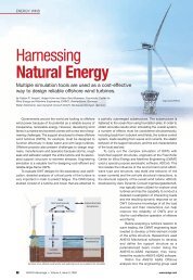
<strong>Hybrid</strong> CFD <strong>for</strong> Wind Turbine Aero<br />
• Conventional CFD methods based on <strong>Navier</strong>-<strong>Stokes</strong> have<br />
serious shortcomings <strong>for</strong> wind turbine analyses<br />
– Very large domain required to en<strong>for</strong>ce far-field boundary conditions<br />
sufficiently far from blade<br />
• Inlet and outlet conditions imposed many blade radii upstream<br />
and downstream<br />
• Periodicity requires large sector (120° <strong>for</strong> 3 blades) to be<br />
modeled<br />
– Results in very large meshes (> 10M nodes), long run times, difficult<br />
post-processing<br />
• Prevents use <strong>of</strong> fine enough mesh near blade needed to capture<br />
turbulence transition effects<br />
• Unsteady CFD simply not practical on such large meshes<br />
– Wake behind blade dissipates too quickly due to numerical<br />
dissipation<br />
• Prior studies have shown need to resolve wake as far as 10-20<br />
blade radii downstream <strong>for</strong> accurate power predictions<br />
© 2008 GE All rights reserved. 3
Full Domain CFD<br />
Outlet<br />
50 m<br />
Inlet<br />
© 2008 GE All rights reserved. 4
<strong>Hybrid</strong> CFD (cont’d)<br />
• <strong>Hybrid</strong> <strong>Navier</strong>-<strong>Stokes</strong>/<strong>Vortex</strong> <strong>Panel</strong> method proposed by<br />
Schmitz, Chattot (UC Davis) looks very promising<br />
– Small <strong>Navier</strong>-<strong>Stokes</strong> region (~1 - 5 M nodes) around the blade<br />
computes near field<br />
– <strong>Vortex</strong> <strong>Panel</strong> method computes far field using Biot-Savart law<br />
• Effect <strong>of</strong> blade on far field represented by lifting line,<br />
helicoidal paths from prescribed wake<br />
Small <strong>Navier</strong>-<br />
<strong>Stokes</strong> domain<br />
Prescribed<br />
wake shape<br />
© 2008 GE All rights reserved. 5
<strong>Hybrid</strong> CFD (cont’d)<br />
• Coupling between near and far fields<br />
– <strong>Navier</strong>-<strong>Stokes</strong> code computes circulation on polylines about<br />
spanwise blade sections needed by <strong>Vortex</strong> panel solver<br />
– <strong>Vortex</strong> panel method computes induced velocities on boundaries<br />
<strong>of</strong> NS region computed from Biot-Savart law<br />
– Effect <strong>of</strong> blade on far field represented by lifting line, helicoidal<br />
paths from prescribed wake<br />
– These provide coupling between <strong>Navier</strong> <strong>Stokes</strong> and <strong>Vortex</strong> <strong>Panel</strong><br />
solvers<br />
© 2008 GE All rights reserved. 6
Goals <strong>for</strong> <strong>Hybrid</strong> CFD <strong>for</strong> Wind<br />
Turbine Aero Design<br />
• Goal is to develop design system using hybrid<br />
methodology that can be routinely used by GE engineers<br />
to design wind turbine blades <strong>for</strong> optimum aero<br />
per<strong>for</strong>mance<br />
– Scripting <strong>of</strong> meshing, pre- and post-processing is essential<br />
– <strong>Hybrid</strong> CFD analysis in CFX must be no more difficult to set up<br />
and run than conventional analysis<br />
– Best practices established and embedded in process<br />
© 2008 GE All rights reserved. 7
<strong>Implementation</strong> <strong>of</strong> <strong>Hybrid</strong> CFD in<br />
CFX<br />
• The hybrid method requires:<br />
– The computation <strong>of</strong> the circulation on closed loops that<br />
include all <strong>of</strong> the sources <strong>of</strong> vorticity<br />
– The calculation <strong>of</strong> the induced velocities and their imposition<br />
on the boundaries<br />
• These calculations are now done as part <strong>of</strong> a single<br />
CFX solver run, instead <strong>of</strong> requiring a separate<br />
program to be run between successive runs <strong>of</strong> CFX<br />
• The vortex panel solver is implemented in CFX User<br />
Fortran (CFX Version 11.0 and up)<br />
© 2008 GE All rights reserved. 8
User Fortran Routines<br />
CFX provides two types <strong>of</strong> User Fortran routines:<br />
• Junction Box routines, which are User Fortran routines that are<br />
called and executed at particular times during a CFX run.<br />
• CEL routines<br />
– These evaluate a function in a similar fashion to CFX expression<br />
language<br />
• We basically need routines to:<br />
– Read the user defined loops upon which to compute the circulation, and<br />
save these in the CFX MMS (memory management system) <strong>for</strong> later<br />
use by the solver<br />
– Compute the helicoidal wake paths<br />
– Compute the circulation on the polylines at the start <strong>of</strong> each CFX<br />
iteration<br />
– Impose the induced velocities on the outer boundary as a prescribed<br />
velocity opening boundary condition<br />
© 2008 GE All rights reserved. 9
Basic <strong>Hybrid</strong> CFD Flow Chart<br />
Initial Setup<br />
Read user input<br />
data files<br />
Generate polylines<br />
Compute helix<br />
Compute circulation<br />
Compute induced velocities<br />
Solve equations<br />
Output results file<br />
© 2008 GE All rights reserved. 10<br />
Iteration Loop<br />
Note<br />
User Fortran routines<br />
shown in yellow
Computing Circulation in CFX<br />
• The circulation is computed on closed loops (polylines) that<br />
include all <strong>of</strong> the sources <strong>of</strong> vorticity<br />
– The circulation calculation is made <strong>for</strong> a number <strong>of</strong> spanwise<br />
positions along the blade<br />
• This calculation is updated every iteration using the current<br />
values <strong>of</strong> the velocity field<br />
• Polyline points are mapped to the closest mesh points<br />
– Velocity vector and gradient returned at mapped points<br />
• User Fortran provides capability to recover gradient operator<br />
– Use Taylor expansion to interpolate solution from mapped point (mp)<br />
to polyline point (pp)<br />
V pp = V mp + ∇V * dr<br />
• Circulation calculation requires parallel implementation<br />
– Simplest parallel implementation is sufficient, as the line integrals are<br />
1D calculations:<br />
– Routines use CFX Flow Parallel message passing calls <strong>for</strong> parallel<br />
communication (as does rest <strong>of</strong> CFX solver)<br />
© 2008 GE All rights reserved. 11
Computation <strong>of</strong> Helicoidal Paths<br />
• Helicoidal paths are computed based on<br />
simple actuator disk theory<br />
• Paths depend on estimated power<br />
coefficient<br />
– Paths are periodically updated during<br />
CFX calculation based on latest<br />
computed power coefficient<br />
• Helicoidal paths computed redundantly on<br />
each processor using a Junction Box<br />
routine<br />
– This allows each processor to<br />
compute induced velocities in perfectly<br />
parallel fashion<br />
<strong>Navier</strong>-<strong>Stokes</strong><br />
domain<br />
Wind<br />
direction<br />
© 2008 GE All rights reserved. 12
Induced Velocities<br />
• The induced velocities are computed on the outer boundary <strong>of</strong><br />
the domain, using the Biot-Savart law<br />
– This involves the line integration along a helicoidal path, starting out<br />
from each spanwise location on the trailing edge<br />
• Outer boundaries <strong>of</strong> <strong>Navier</strong>-<strong>Stokes</strong> domain are treated as<br />
openings<br />
– Induced velocity on boundary is defined as an expression, which is<br />
provided by a user CEL function<br />
– Influence coefficients computed at beginning <strong>of</strong> run, and stored in<br />
MMS<br />
– Subsequent updates <strong>of</strong> induced velocities use stored coefficients<br />
• Influence coefficients updated periodically to reflect updated<br />
helicoidal paths<br />
© 2008 GE All rights reserved. 13
Equations <strong>for</strong> Induced Velocities<br />
Induced Velocities (Biot-Savart Law)<br />
Influence Coefficients<br />
All equations from<br />
Schmitz’ thesis<br />
© 2008 GE All rights reserved. 14
Computation <strong>of</strong> Induced Velocities<br />
• Total storage requirement<br />
– (6 influence coefficients) X (nbf<br />
boundary faces) X (jx polylines)<br />
– For 100,000 boundary faces, 40<br />
polylines 100 MB storage<br />
– Typically represents about 20%<br />
additional storage <strong>for</strong> solver<br />
• Each processor needs only to<br />
compute influence coefficients,<br />
induced velocities just <strong>for</strong> its<br />
boundary faces<br />
– Naturally parallel !<br />
– Storage is distributed across<br />
processors<br />
© 2008 GE All rights reserved. 15
Specification <strong>of</strong> BCs in CFX<br />
© 2008 GE All rights reserved. 16
Mesh Generation<br />
• The blade geometry is created in<br />
Unigraphics, and imported into ICEM-<br />
CFD <strong>for</strong> meshing<br />
• Restrictions on <strong>Navier</strong>-<strong>Stokes</strong> domain:<br />
– Needs to contain polylines <strong>for</strong> computation <strong>of</strong><br />
the circulation<br />
– Exit plane should be orthogonal to wake path<br />
• A grid template with a C-H topology has<br />
been developed to simplify the mesh<br />
generation process<br />
– The blocking file can be imported to any<br />
ICEM project with the same parts and<br />
adapted to a new blade geometry<br />
© 2008 GE All rights reserved. 17
Creating the polylines<br />
• The polylines over which the circulation is computed are<br />
generated using two utility programs:<br />
– BladeContours<br />
• A CFX-POST Power Syntax script file that extracts the<br />
contours <strong>of</strong> the blade cross sections at the spanwise locations<br />
where the polylines are desired<br />
• These blade contours are then input to<br />
– PolyGen<br />
• A program that created closed polylines that are <strong>of</strong>fset from<br />
the blade contours<br />
• The polylines, and the location <strong>of</strong> the leading and trailing edge<br />
locations <strong>of</strong> the spanwise blade sections are written into files<br />
that are input files <strong>for</strong> the CFX run<br />
© 2008 GE All rights reserved. 18
Generation <strong>of</strong> the polylines<br />
Screen shot from BladeContours script,<br />
showing spanwise blade contours<br />
Polylines <strong>for</strong> NREL wind turbine<br />
blade<br />
© 2008 GE All rights reserved. 19
Post-processing<br />
• Post-processing <strong>of</strong> the results is also per<strong>for</strong>med using a<br />
CFX-Post Power Syntax script<br />
– Normal and tangential directions input <strong>for</strong> each spanwise blade<br />
section<br />
– At each section, script calculates:<br />
• Normal and tangential <strong>for</strong>ces<br />
• Pressure coefficients<br />
• Torque <strong>for</strong>ce<br />
• Same post-processing script used <strong>for</strong> full-domain and<br />
hybrid CFD computations to facilitate comparisons<br />
© 2008 GE All rights reserved. 20
NREL Validation Case<br />
• National Renewable Energy Laboratory (NREL) per<strong>for</strong>med detailed<br />
wind tunnel experiments on 10m diameter wind turbine in NASA Ames<br />
wind tunnel<br />
• This was the test case used by Sven Schmitz (UC Davis) to help<br />
develop the hybrid methodology<br />
• Calculated torque values, pressure distributions match experiment very<br />
well <strong>for</strong> low wind speeds<br />
– 7 & 9 [m/s] cases are attached flow<br />
<strong>Hybrid</strong> CFD<br />
© 2008 GE All rights reserved. 21<br />
Pressure distribution at 63% span<br />
– 7 m/s wind speed
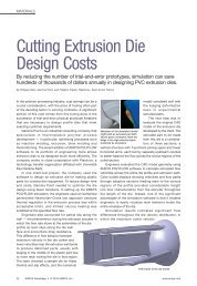
GE46 Validation Case<br />
<strong>Navier</strong>-<strong>Stokes</strong> domain<br />
• This was the first GE blade run<br />
using the hybrid CFD method<br />
• Comparisons made to full-domain<br />
CFD, other analytical methods<br />
– Power predictions match well <strong>for</strong><br />
attached flow cases<br />
Power Coefficient<br />
Tip Speed Ratio<br />
Pressure Coefficient (PC) Comparison<br />
CPU time (min)<br />
400<br />
350<br />
300<br />
250<br />
200<br />
150<br />
100<br />
50<br />
0 Solver time [min]<br />
Full CFD 366<br />
<strong>Hybrid</strong> CFD<br />
46.9<br />
Run Time Comparison<br />
(equal # iterations)<br />
Computed Mach Numbers (TSR=8)<br />
© 2008 GE All rights reserved. 22
Sensitivity Study<br />
• Sensitivity studies are being per<strong>for</strong>med to investigate the<br />
effects <strong>of</strong> a number <strong>of</strong> parameters, and to establish best<br />
practices<br />
• Parameters under study:<br />
– Size <strong>of</strong> <strong>Navier</strong>-<strong>Stokes</strong> domain<br />
– Grid size<br />
– Number <strong>of</strong> polylines<br />
– Location, orientation <strong>of</strong> polylines<br />
• Results appear to be relatively insensitive<br />
© 2008 GE All rights reserved. 23
Example: Effect <strong>of</strong> Domain Size<br />
• Vary size <strong>of</strong> <strong>Navier</strong>-<br />
<strong>Stokes</strong> domain, from<br />
one chord (C=1)<br />
down to ¼ chord<br />
• Vorticity field<br />
starts to look<br />
unphysical if<br />
domain is made<br />
too small<br />
Vorticity at 20% Span<br />
(a)<br />
(b)<br />
(c)<br />
(d)<br />
Full domain CFD<br />
<strong>Hybrid</strong> (C=1)<br />
<strong>Hybrid</strong> (C=½)<br />
<strong>Hybrid</strong> (C=¼)<br />
© 2008 GE All rights reserved. 24<br />
(a)<br />
(c)<br />
(b)<br />
(d)
Future Work<br />
• <strong>Hybrid</strong> methodology allows fine enough<br />
grid in <strong>Navier</strong>-<strong>Stokes</strong> domain to allow<br />
transition to be modeled<br />
– Initial calculations with Langtry-Menter<br />
transition model look very promising<br />
• Reduction in run time makes transient<br />
simulations possible<br />
– Unsteady hybrid analysis capability<br />
currently under development (w/ UC Davis)<br />
© 2008 GE All rights reserved. 25
Concluding Remarks<br />
• <strong>Hybrid</strong> CFD approach looks very promising <strong>for</strong> wind<br />
turbine aerodynamic analyses<br />
– Grid size and run times much less than full domain CFD<br />
– Results similar to full-domain CFD<br />
– Results reasonably insensitive to size <strong>of</strong> <strong>Navier</strong>-<strong>Stokes</strong> domain<br />
and location <strong>of</strong> polylines<br />
• User Fortran in CFX solver and Power Scripting in CFX-<br />
POST allows the development <strong>of</strong> an integrated hybrid<br />
CFD design system<br />
© 2008 GE All rights reserved. 26
Impact<br />
<strong>Hybrid</strong> CFD – Represents a unique differentiating<br />
technology that will be a prime enabler <strong>for</strong> next<br />
generation quiet, efficient wind turbine blades<br />
– Hi-fidelity 3D aerodynamic design<br />
– Low noise design with CFD-based or direct CAA<br />
noise prediction<br />
– Aero-elastic fully-coupled design methods<br />
© 2008 GE All rights reserved. 27