Operating Instructions And Parts Manual Drill Press - JET Tools
Operating Instructions And Parts Manual Drill Press - JET Tools
Operating Instructions And Parts Manual Drill Press - JET Tools

You also want an ePaper? Increase the reach of your titles
YUMPU automatically turns print PDFs into web optimized ePapers that Google loves.
Assembly<br />
Read and understand all assembly<br />
instructions before attempting assembly!<br />
Failure to comply may cause serious injury!<br />
Before Assembly<br />
1. Remove the contents from the shipping<br />
container.<br />
2. Compare the contents of the shipping<br />
container with the list found above. Report<br />
any shortages or damage to your <strong>JET</strong><br />
distributor.<br />
3. Clean all rust protected surfaces with<br />
kerosene or a light solvent. Do not use<br />
lacquer thinner, paint thinner, or gasoline.<br />
These will damage plastic components and<br />
painted surfaces.<br />
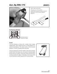
Column Assembly<br />
Referring to Figure 1:<br />
1. Place the base (A) on a level floor.<br />
2. Place the column assembly (B) on the base<br />
(A) and align the holes in the column<br />
support with the holes in the base.<br />
Note: The column shown in Figure 1 is for<br />
the JDP-15MF. While the JDP-15M column<br />
is slightly different in appearance, the<br />
assembly procedure is the same.<br />
3. Using a 17mm wrench, secure the column<br />
(B) with four M10 x 40 hex cap screws (C) to<br />
the base.<br />
Referring to Figures 2 and 3:<br />
4. Remove the wrap and take the rack ring (D)<br />
and rack (B) off the column (C).<br />
5. Install the table bracket (A) together with the<br />
rack (B) as shown in Figure 2.<br />
Figure 2<br />
6. Slide the rack ring (D) over the column (C),<br />
placing it so it rests against the rack (B) as<br />
shown in Figure 3 and tighten firmly.<br />
Figure 3<br />
Figure 1<br />
Table Bracket<br />
When shipped, the rack ring and rack are<br />
bundled together with the column in plastic<br />
wrap.<br />
Crank Handle and Table Lock Handle<br />
Referring to Figure 4 (shown already<br />
assembled):<br />
1. Loosen the setscrew (B) on the table crank<br />
handle (A).<br />
2. Slide the handle (A) onto the table bracket<br />
shaft.<br />
3. Turn the handle until the setscrew is<br />
opposite the flat section on the shaft, and<br />
tighten the setscrew to secure the handle.<br />
4. Install the table lock handle (C), but do not<br />
tighten.<br />
8