Operating Instructions And Parts Manual Drill Press - JET Tools
Operating Instructions And Parts Manual Drill Press - JET Tools
Operating Instructions And Parts Manual Drill Press - JET Tools

Create successful ePaper yourself
Turn your PDF publications into a flip-book with our unique Google optimized e-Paper software.
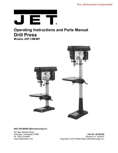
<strong>Operating</strong> <strong>Instructions</strong> and <strong>Parts</strong> <strong>Manual</strong><br />
<strong>Drill</strong> <strong>Press</strong><br />
Models JDP-15M/MF<br />
WALTER MEIER (Manufacturing) Inc.<br />
427 New Sanford Road<br />
LaVergne, Tennessee 37086 Part No. M-354165<br />
Ph.: 800-274-6848 Revision A1 04/2010<br />
www.waltermeier.com<br />
Copyright © 2010 Walter Meier (Manufacturing) Inc.
Warranty and Service<br />
Walter Meier (Manufacturing) Inc., warrants every product it sells. If one of our tools needs service or repair, one of<br />
our Authorized Service Centers located throughout the United States can give you quick service. In most cases, any<br />
of these Walter Meier Authorized Service Centers can authorize warranty repair, assist you in obtaining parts, or<br />
perform routine maintenance and major repair on your <strong>JET</strong>® tools. For the name of an Authorized Service Center in<br />
your area call 1-800-274-6848.<br />
MORE INFORMATION<br />
Walter Meier is consistently adding new products to the line. For complete, up-to-date product information, check with<br />
your local Walter Meier distributor, or visit waltermeier.com.<br />
WARRANTY<br />
<strong>JET</strong> products carry a limited warranty which varies in duration based upon the product (MW = Metalworking, WW =<br />
Woodworking).<br />
WHAT IS COVERED?<br />
This warranty covers any defects in workmanship or materials subject to the exceptions stated below. Cutting tools,<br />
abrasives and other consumables are excluded from warranty coverage.<br />
WHO IS COVERED?<br />
This warranty covers only the initial purchaser of the product.<br />
WHAT IS THE PERIOD OF COVERAGE?<br />
The general <strong>JET</strong> warranty lasts for the time period specified in the product literature of each product.<br />
WHAT IS NOT COVERED?<br />
Five Year Warranties do not cover woodworking (WW) products used for commercial, industrial or educational<br />
purposes. Woodworking products with Five Year Warranties that are used for commercial, industrial or education<br />
purposes revert to a One Year Warranty. This warranty does not cover defects due directly or indirectly to misuse,<br />
abuse, negligence or accidents, normal wear-and-tear, improper repair or alterations, or lack of maintenance.<br />
HOW TO GET SERVICE<br />
The product or part must be returned for examination, postage prepaid, to a location designated by us. For the name<br />
of the location nearest you, please call 1-800-274-6848.<br />
You must provide proof of initial purchase date and an explanation of the complaint must accompany the<br />
merchandise. If our inspection discloses a defect, we will repair or replace the product, or refund the purchase price,<br />
at our option. We will return the repaired product or replacement at our expense unless it is determined by us that<br />
there is no defect, or that the defect resulted from causes not within the scope of our warranty in which case we will,<br />
at your direction, dispose of or return the product. In the event you choose to have the product returned, you will be<br />
responsible for the shipping and handling costs of the return.<br />
HOW STATE LAW APPLIES<br />
This warranty gives you specific legal rights; you may also have other rights which vary from state to state.<br />
LIMITATIONS ON THIS WARRANTY<br />
WALTER MEIER (MANUFACTURING) INC., LIMITS ALL IMPLIED WARRANTIES TO THE PERIOD OF THE<br />
LIMITED WARRANTY FOR EACH PRODUCT. EXCEPT AS STATED HEREIN, ANY IMPLIED WARRANTIES OR<br />
MERCHANTABILITY AND FITNESS ARE EXCLUDED. SOME STATES DO NOT ALLOW LIMITATIONS ON HOW<br />
LONG THE IMPLIED WARRANTY LASTS, SO THE ABOVE LIMITATION MAY NOT APPLY TO YOU.<br />
WALTER MEIER SHALL IN NO EVENT BE LIABLE FOR DEATH, INJURIES TO PERSONS OR PROPERTY, OR<br />
FOR INCIDENTAL, CONTINGENT, SPECIAL, OR CONSEQUENTIAL DAMAGES ARISING FROM THE USE OF<br />
OUR PRODUCTS. SOME STATES DO NOT ALLOW THE EXCLUSION OR LIMITATION OF INCIDENTAL OR<br />
CONSEQUENTIAL DAMAGES, SO THE ABOVE LIMITATION OR EXCLUSION MAY NOT APPLY TO YOU.<br />
Walter Meier sells through distributors only. The specifications in Walter Meier catalogs are given as general<br />
information and are not binding. Members of Walter Meier reserve the right to effect at any time, without prior notice,<br />
those alterations to parts, fittings, and accessory equipment which they may deem necessary for any reason<br />
whatsoever. <strong>JET</strong>® branded products are not sold in Canada by Walter Meier.<br />
2
Table of Contents<br />
Table of Contents ...............................................................................................................................3<br />
Warnings............................................................................................................................................4<br />
Specifications .....................................................................................................................................6<br />
Shipping Contents ..............................................................................................................................7<br />
Required <strong>Tools</strong> ...................................................................................................................................7<br />
Assembly ...........................................................................................................................................8<br />
Before Assembly .............................................................................................................................8<br />
Column Assembly ...........................................................................................................................8<br />
Table Bracket ..................................................................................................................................8<br />
Crank Handle and Table Lock Handle...............................................................................................8<br />
Column Lock Handle .......................................................................................................................9<br />
Table Installation .............................................................................................................................9<br />
Head Assembly ...............................................................................................................................9<br />
Chuck and Arbor Installation ............................................................................................................9<br />
Chuck and Arbor Removal ............................................................................................................. 10<br />
Adjustment ....................................................................................................................................... 10<br />
Depth Stop Adjustment .................................................................................................................. 10<br />
Changing Spindle Speeds .............................................................................................................. 10<br />
Return Spring Adjustment .............................................................................................................. 11<br />
Work Light .................................................................................................................................... 12<br />
Table Tilt Adjustment ..................................................................................................................... 12<br />
Operation ......................................................................................................................................... 12<br />
Installing <strong>Drill</strong>s ............................................................................................................................... 12<br />
Positioning the Workpiece .............................................................................................................. 12<br />
Using the Vise ............................................................................................................................... 12<br />
Basic Operation............................................................................................................................. 12<br />
Maintenance .................................................................................................................................... 13<br />
Lubrication ....................................................................................................................................... 13<br />
Electrical .......................................................................................................................................... 13<br />
115 Volt Operation ........................................................................................................................ 13<br />
230 Volt Operation ........................................................................................................................ 13<br />
Grounding <strong>Instructions</strong> ................................................................................................................... 14<br />
Extension Cords ............................................................................................................................ 14<br />
Troubleshooting ................................................................................................................................ 15<br />
Replacement <strong>Parts</strong> ........................................................................................................................... 16<br />
Exploded View Drawing JDP-15M/MF ............................................................................................ 17<br />
<strong>Parts</strong> List JDP-15M/MF .................................................................................................................. 18<br />
<strong>Parts</strong> List JDP-15M/MF .................................................................................................................. 19<br />
<strong>Parts</strong> List JDP-15M/MF .................................................................................................................. 20<br />
Wiring Diagram................................................................................................................................. 21<br />
JDP – 15M/MF – 115V................................................................................................................... 21<br />
JDP – 15M/MF – 230V................................................................................................................... 21<br />
The specifications in this manual are given as general information and are not binding. Walter Meier<br />
(Manufacturing) Inc., reserves the right to effect, at any time and without prior notice, changes or<br />
alterations to parts, fittings, and accessory equipment deemed necessary for any reason whatsoever.<br />
3
Warnings<br />
1. Read and understand the entire owners manual before attempting assembly or operation.<br />
2. Read and understand the warnings posted on the machine and in this manual. Failure to comply with<br />
all of these warnings may cause serious injury.<br />
3. Replace the warning labels if they become obscured or removed.<br />
4. This drill press is designed and intended for use by properly trained and experienced personnel only.<br />
If you are not familiar with the proper and safe operation of a drill press, do not use until proper<br />
training and knowledge have been obtained.<br />
5. Do not use this drill press for other than its intended use. If used for other purposes, Walter Meier<br />
(Manufacturing) Inc., disclaims any real or implied warranty and holds itself harmless from any injury<br />
that may result from that use.<br />
6. Always wear approved safety glasses/face shields while using this drill press. Everyday eyeglasses<br />
only have impact resistant lenses; they are not safety glasses.<br />
7. Before operating this drill press, remove tie, rings, watches and other jewelry, and roll sleeves up past<br />
the elbows. Remove all loose clothing and confine long hair. Non-slip footwear or anti-skid floor strips<br />
are recommended. Do not wear gloves.<br />
8. Wear ear protectors (plugs or muffs) during extended periods of operation.<br />
9. Some dust created by power sanding, sawing, grinding, drilling and other construction activities<br />
contain chemicals known to cause cancer, birth defects or other reproductive harm. Some examples<br />
of these chemicals are:<br />
• Lead from lead based paint.<br />
• Crystalline silica from bricks, cement and other masonry products.<br />
• Arsenic and chromium from chemically treated lumber.<br />
Your risk of exposure varies, depending on how often you do this type of work. To reduce your<br />
exposure to these chemicals, work in a well-ventilated area and work with approved safety<br />
equipment, such as face or dust masks that are specifically designed to filter out microscopic<br />
particles.<br />
10. Do not operate this machine while tired or under the influence of drugs, alcohol or any medication.<br />
11. Make certain the switch is in the OFF position before connecting the machine to the power supply.<br />
12. Make certain the machine is properly grounded.<br />
13. Make all machine adjustments or maintenance with the machine unplugged from the power source.<br />
14. Remove adjusting keys and wrenches. Form a habit of checking to see that keys and adjusting<br />
wrenches are removed from the machine before turning it on.<br />
15. Keep safety guards in place at all times when the machine is in use. If removed for maintenance<br />
purposes, use extreme caution and replace the guards immediately.<br />
16. Make sure the drill press is firmly secured to the floor or bench before use.<br />
17. Check damaged parts. Before further use of the machine, a guard or other part that is damaged<br />
should be carefully checked to determine that it will operate properly and perform its intended<br />
function. Check for alignment of moving parts, binding of moving parts, breakage of parts, mounting<br />
and any other conditions that may affect its operation. A guard or other part that is damaged should<br />
be properly repaired or replaced.<br />
18. Provide for adequate space surrounding work area and non-glare, overhead lighting.<br />
19. Keep the floor around the machine clean and free of scrap material, oil and grease.<br />
4
20. Keep visitors a safe distance from the work area. Keep children away.<br />
21. Make your workshop child proof with padlocks, master switches or by removing starter keys.<br />
22. Give your work undivided attention. Looking around, carrying on a conversation and “horse-play” are<br />
careless acts that can result in serious injury.<br />
23. Maintain a balanced stance at all times so that you do not fall or lean against the spindle or other<br />
moving parts. Do not overreach or use excessive force to perform any machine operation.<br />
24. Use the right tool at the correct speed and feed ra t e. Do not force a tool or attachment to do a job for<br />
which it was not designed. The right tool will do the job better and safer.<br />
25. Use recommended accessories; improper accessories may be hazardous.<br />
26. Maintain tools with care. Keep drill bits sharp and clean for the best and safest performance. Follow<br />
instructions for lubricating and changing accessories.<br />
27. Make sure the work piece is securely attached or clamped to the table. Never use your hand to hold<br />
the work piece.<br />
28. Turn off the machine before cleaning. Use a brush or compressed air to remove chips or debris — do<br />
not use your hands.<br />
29. Do not stand on the machine. Serious injury could occur if the machine tips over.<br />
30. Never leave the machine running unattended. Turn the power off and do not leave the machine until it<br />
comes to a complete stop.<br />
31. Remove loose items and unnecessary work pieces from the area before starting the machine.<br />
Familiarize yourself with the following safety notices used in this manual:<br />
This means that if precautions are not heeded, it may result in minor injury and/or<br />
possible machine damage.<br />
even death.<br />
This means that if precautions are not heeded, it may result in serious injury or possibly<br />
- - SAVE THESE INSTRUCTIONS - -<br />
5
Specifications<br />
Model Number ............................................................JDP-15M........................................... JDP-15MF<br />
Stock Number .............................................................. 354165................................................ 354166<br />
Swing.................................................................................. 15”....................................................... 15"<br />
Type .............................................................................. Bench.................................................... Floor<br />
<strong>Drill</strong>ing Capacity.................................................................. 5/8”...................................................... 5/8”<br />
Chuck Size ......................................................................... 5/8”...................................................... 5/8”<br />
Spindle Travel ................................................................. 3-1/8”................................................... 3-1/8”<br />
Spindle Distance to Base ............................................... 16-1/2”....................................................... 48"<br />
Spindle Distance to Table (max.) .......................................... 24”....................................................... 29"<br />
Table Size (Length x Width) ...................................16-1/2" x 13".........................................16-1/2" x 13"<br />
Spindle Taper ........................................................... MT-2/JT-3............................................ MT-2/JT-3<br />
Column Diameter............................................................. 2-7/8”................................................... 2-7/8”<br />
Number of Spindle Speeds .................................................... 16........................................................ 16<br />
Range of Spindle Speeds (RPM) .............................. 200 - 3,630........................................... 200 - 3,630<br />
Base Size........................................................ 10-7/8” x 18-1/2”......................................... 11” x 19-3/4”<br />
Overall Dimensions (H x W x D)..................... 39-1/2" x 13" x 31"...................................... 63" x 13" x 31"<br />
Motor .................................. TEFC 3/4HP, 115/230V, 60Hz, 1Ph....... TEFC 3/4HP, 115/230V, 60Hz, 1Ph<br />
Net Weight, approximate .............................................. 156 lbs................................................. 161 lbs.<br />
Gross Weight, approximate ........................................... 163 lbs................................................. 167 lbs.<br />
Carton Size (L x W x H/in): ..................................... 32 x 22 x 12......................................... 56 x 20 x 11<br />
The above specifications were current at the time this manual was published, but because of our policy of<br />
continuous improvement, Walter Meier (Manufacturing) Inc., reserves the right to change specifications at<br />
any time and without prior notice, without incurring obligations.<br />
6
Shipping Contents<br />
Unpack the carton and verify that all parts listed<br />
below are included.<br />
Main <strong>Parts</strong><br />
1 ea Head Assembly<br />
1 ea Table<br />
1 set Column and Table Bracket Assembly<br />
1 ea Base<br />
Additional <strong>Parts</strong><br />
1. 1 set Chuck and Chuck Key<br />
2. 1 pc Arbor<br />
3. 1 pc Drift Key<br />
4. 1 pc Table Crank Handle<br />
5. 1 pc Table Lock Handle<br />
6. 1 pc Column Lock Handle<br />
7. 3 pcs Downfeed Handles and Knobs<br />
8. 4 pcs M10 x 40 Hex Cap Screws<br />
9. 1 set Hex Wrenches (3mm, 5mm, 6mm)<br />
Other Material<br />
1 ea Owner’s <strong>Manual</strong><br />
1 ea Warranty Registration Card<br />
Required <strong>Tools</strong><br />
1. 17mm Box Wrench or a 6” – 8” Adjustable<br />
Wrench<br />
2. 15/16" wrench<br />
Additional <strong>Parts</strong><br />
7
Assembly<br />
Read and understand all assembly<br />
instructions before attempting assembly!<br />
Failure to comply may cause serious injury!<br />
Before Assembly<br />
1. Remove the contents from the shipping<br />
container.<br />
2. Compare the contents of the shipping<br />
container with the list found above. Report<br />
any shortages or damage to your <strong>JET</strong><br />
distributor.<br />
3. Clean all rust protected surfaces with<br />
kerosene or a light solvent. Do not use<br />
lacquer thinner, paint thinner, or gasoline.<br />
These will damage plastic components and<br />
painted surfaces.<br />
Column Assembly<br />
Referring to Figure 1:<br />
1. Place the base (A) on a level floor.<br />
2. Place the column assembly (B) on the base<br />
(A) and align the holes in the column<br />
support with the holes in the base.<br />
Note: The column shown in Figure 1 is for<br />
the JDP-15MF. While the JDP-15M column<br />
is slightly different in appearance, the<br />
assembly procedure is the same.<br />
3. Using a 17mm wrench, secure the column<br />
(B) with four M10 x 40 hex cap screws (C) to<br />
the base.<br />
Referring to Figures 2 and 3:<br />
4. Remove the wrap and take the rack ring (D)<br />
and rack (B) off the column (C).<br />
5. Install the table bracket (A) together with the<br />
rack (B) as shown in Figure 2.<br />
Figure 2<br />
6. Slide the rack ring (D) over the column (C),<br />
placing it so it rests against the rack (B) as<br />
shown in Figure 3 and tighten firmly.<br />
Figure 3<br />
Figure 1<br />
Table Bracket<br />
When shipped, the rack ring and rack are<br />
bundled together with the column in plastic<br />
wrap.<br />
Crank Handle and Table Lock Handle<br />
Referring to Figure 4 (shown already<br />
assembled):<br />
1. Loosen the setscrew (B) on the table crank<br />
handle (A).<br />
2. Slide the handle (A) onto the table bracket<br />
shaft.<br />
3. Turn the handle until the setscrew is<br />
opposite the flat section on the shaft, and<br />
tighten the setscrew to secure the handle.<br />
4. Install the table lock handle (C), but do not<br />
tighten.<br />
8
Head Assembly<br />
Referring to Figure 7:<br />
1. With the aid of a second person, carefully lift<br />
the head onto the column top and slide it<br />
down into position<br />
Figure 4<br />
Column Lock Handle<br />
Referring to Figure 5:<br />
Thread the column lock handle (D) into the table<br />
bracket (E).<br />
The head assembly is heavy! Use care when<br />
lifting onto the column!<br />
2. Rotate head assembly until sides of the<br />
pulley cover are parallel with the sides of the<br />
base.<br />
3. Tighten two setscrews (A) with a 5mm hex<br />
wrench (provided) until they are snug.<br />
Figure 5<br />
Table Installation<br />
Referring to Figure 6:<br />
1. Place the table (A) on the bracket (B).<br />
2. Tighten the table lock handle (C).<br />
Figure 7<br />
4. Install three downfeed handles (B) into the<br />
downfeed hub (C).<br />
Chuck and Arbor Installation<br />
Referring to Figure 8:<br />
1. Twist the chuck (B) to retract the chuck jaws<br />
if they are exposed.<br />
2. Install the chuck (B) to the arbor (A) tightly.<br />
3. Insert the chuck and arbor assembly into the<br />
spindle (C). Pull the downfeed handle down<br />
to press the arbor in place.<br />
Note: Put a piece of scrap wood (D) on the table<br />
to protect the chuck nose when pulling the<br />
downfeed handle (E) down to press into place.<br />
Figure 6<br />
9
1. Use a pencil to mark the depth the bit will<br />
drill into the workpiece.<br />
2. With the drill bit in the chuck, lower<br />
downfeed handle to advance bit to your<br />
mark (A).<br />
3. With your other hand, advance the lock nuts<br />
(B) on the depth stop rod until they are snug<br />
to the seat (C).<br />
4. The drill bit will now advance to this point.<br />
5. To release, advance the nuts counterclockwise<br />
to the top of the depth stop.<br />
Figure 8<br />
Chuck and Arbor Removal<br />
Referring to Figure 9:<br />
1. Unplug machine from the power source.<br />
2. Raise the table until it is about seven inches<br />
below the chuck.<br />
3. Place a piece of scrap wood on the table,<br />
and lower quill (A) using the downfeed<br />
handle.<br />
4. Rotate spindle to align the keyhole in the<br />
spindle with the keyhole in the quill.<br />
5. Insert the drift key (B) into the aligned slots<br />
and tap lightly. The chuck and arbor<br />
assembly should fall from the spindle.<br />
Adjustment<br />
Figure 9<br />
Depth Stop Adjustment<br />
Referring to Figure 10:<br />
To drill multiple holes at the same preset depth,<br />
use the depth stop:<br />
10<br />
Figure 10<br />
Changing Spindle Speeds<br />
A spindle speed and pulley/belt arrangement<br />
chart is found on the inside of the pulley cover<br />
(D, Fig. 11). The chart is also shown in Figure<br />
12. Refer to this chart whenever changing<br />
speeds.<br />
To change spindle speeds:<br />
1. Unplug the machine from the power source.<br />
2. Loosen two bar knobs (E, Fig. 11) found on<br />
each side of the head assembly.<br />
3. Rotate the tension adjuster clockwise (F,<br />
Fig. 11) to bring the motor base as close to<br />
the head as possible.<br />
4. For desired speed, change the location of<br />
belts per pulley/belt arrangement chart.<br />
5. Rotate the tension adjuster<br />
counterclockwise (F. Fig. 11) to tension the<br />
belts.
6. Tighten two bar knobs (E, Fig. 11). Belts<br />
are properly tensioned when finger and<br />
thumb pressure midway between the two<br />
pulleys causes approximately ½” deflection.<br />
Figure 11<br />
Figure 12<br />
Return Spring Adjustment<br />
The return spring is adjusted at the factory and<br />
should not need further adjustment. If<br />
adjustment is deemed necessary, follow the<br />
steps below while referring to Figure 13:<br />
1. Unplug the machine from the power source.<br />
2. Loosen two hex nuts (A). Do not remove.<br />
3. Firmly hold the coil spring cover (B).<br />
4. Pull out the cover and rotate until the pin (C)<br />
on the return spring plate engages the next<br />
notch in the coil spring cover. Turn the<br />
cover clockwise to decrease tension and<br />
counter-clockwise to increase tension.<br />
5. Tighten two hex nuts (A). Do not overtighten.<br />
Nuts should not contact the housing<br />
when tight. The hex nuts should be<br />
tightened against each other.<br />
Figure 13<br />
11
Work Light<br />
Install a light bulb, no larger than 60 watts into<br />
the socket accessed from beneath the head.<br />
The rocker switch controls the light switch (D,<br />
Fig. 13). IMPORTANT: If the drill press is<br />
connected to 230 volt power, you must install a<br />
bulb rated for 230 volt.<br />
Table Tilt Adjustment<br />
The table tilt adjustments are made on the table<br />
bracket under the table.<br />
To tilt the table (refer to Figures 14 and 15):<br />
In the following steps do not over loosen.<br />
This could result in the table assembly to<br />
separate from the column, fall and cause<br />
injury.<br />
1. Loosen the socket head set screw (A) with a<br />
3mm hex wrench.<br />
2. Using a 15/16" wrench, loosen the hex cap<br />
screw (B), and tilt the table to the desired<br />
angle by aligning the arrow (C, Fig. 15) on<br />
the rotating part of the bracket to the desired<br />
angle (in degrees) displayed on the scale<br />
(D, Fig 15) at the base of the bracket.<br />
3. Tighten the hex cap screw (B).<br />
4. Tighten the socket head set screw (A).<br />
Operation<br />
Figure 15<br />
Installing <strong>Drill</strong>s<br />
Insert the drill into the chuck jaws about<br />
1" (25.4mm) long. When using a small drill do<br />
not insert it so far that the jaws touch the flutes<br />
of the drill. Make sure that the drill is centered in<br />
the chuck before tightening the chuck with the<br />
key.<br />
Positioning the Workpiece<br />
Always place a piece of wood (or plywood) on<br />
the table. This will prevent "splintering" or<br />
making heavy burrs on the underside of the<br />
workpiece as the drill breaks through. The wood<br />
should contact the left side of the column.<br />
Using the Vise<br />
For the small workpiece that cannot be clamped<br />
to the table, use a drill press vise. The vise must<br />
be clamped or bolted to the table. Always use a<br />
back-up piece of scrap wood to cover the table.<br />
This protects both the table and the drill bit.<br />
Basic Operation<br />
Place material to be drilled in such as way as to<br />
come into contact with the left side of the<br />
column. This prevents the material from<br />
spinning.<br />
Figure 14<br />
12<br />
If the work piece is not large enough to come<br />
into contact with the column, use a clamp or<br />
drill press vise that is securely fastened to<br />
the table! Failure to comply may cause<br />
serious injury!<br />
Feed the bit into the material with only enough<br />
force to allow the drill bit to work. Feeding too<br />
slowly may cause burning of the workpiece.<br />
Feeding too quickly may cause the motor to stop<br />
and/or the drill bit to break.
Generally speaking, the smaller the drill bit, the<br />
greater the RPM required. Wood requires higher<br />
speeds than metal. Metal is usually drilled at<br />
slower speeds.<br />
In dusty environments, frequently blow out any<br />
dust that accumulates inside the motor.<br />
Maintenance<br />
Before any intervention on the machine,<br />
disconnect it from the electrical supply by<br />
pulling out the plug or switching off the main<br />
switch! Failure to comply may cause serious<br />
injury.<br />
A coat of automobile-type wax applied to the<br />
table and column will help to keep the surfaces<br />
clean.<br />
If the power cord is worn, cut, or damaged in<br />
any way, have it replaced immediately.<br />
Lubrication<br />
All of the ball bearings are packed with grease at<br />
the factory. They require no further lubrication.<br />
Periodically lubricate the gear, rack, table<br />
elevation mechanism, the splines (grooves) in<br />
the spindle, and the teeth of the quill with a #2<br />
tube grease.<br />
Electrical<br />
115 Volt Operation<br />
Referring to Figure 16:<br />
As received from the factory, your drill press is<br />
ready to run at 115-volt operation. This drill<br />
press, when wired for 115 volt, is intended for<br />
use on a circuit that has an outlet and a plug that<br />
looks like the one illustrated in (A). A temporary<br />
adapter, which looks like the adapter shown in<br />
(B), may be used to connect this plug to a twopole<br />
receptacle if a properly grounded outlet is<br />
not available. The temporary adapter should<br />
only be used until a properly grounded outlet<br />
can be installed by a qualified electrician. This<br />
adapter is not applicable in Canada. The green<br />
colored rigid ear, lug, or tab, extending from the<br />
adapter, must be connected to a permanent<br />
ground such as a properly grounded outlet box.<br />
Figure 16<br />
230 Volt Operation<br />
Referring to Figure 17:<br />
If 230V, single-phase operation is desired, the<br />
following instructions must be followed:<br />
1. Disconnect the machine from the power<br />
source.<br />
2. The <strong>JET</strong> drill press motor has four<br />
numbered leads that are factory connected<br />
for 115V operation, as shown in (A). For<br />
230V operation reconnect the leads as<br />
shown in (B).<br />
3. The 115V attachment plug (C), supplied with<br />
the drill press, must be replaced with a<br />
UL/CSA listed plug suitable for 230V<br />
operation (D). Contact your local Authorized<br />
<strong>JET</strong> Service Center or qualified electrician<br />
for proper procedures to install the plug.<br />
The drill press must comply with all local and<br />
national codes after the 230-volt plug is<br />
installed.<br />
4. The drill press with a 230-volt plug should<br />
only be connected to an outlet having the<br />
same configuration as shown in (D). No<br />
adapter is available nor should be used with<br />
the 230-volt plug.<br />
5. The bulb installed in the work light must be<br />
rated for 230 volt power.<br />
Figure 17<br />
13
Grounding <strong>Instructions</strong><br />
This tool must be grounded while in use to<br />
protect the operator from electric shock.<br />
In the event of a malfunction or breakdown,<br />
grounding provides a path of least resistance for<br />
electric current to reduce the risk of electric<br />
shock. This tool is equipped with an electric cord<br />
having an equipment-grounding conductor and a<br />
grounding plug. The plug must be plugged into a<br />
matching outlet that is properly installed and<br />
grounded in accordance with all local codes and<br />
ordinances.<br />
Do not modify the plug provided. If it will not fit<br />
the outlet, have the proper outlet installed by a<br />
qualified electrician.<br />
Improper connection of the equipmentgrounding<br />
conductor can result in a risk of<br />
electric shock. The conductor, with insulation<br />
having an outer surface that is green with or<br />
without yellow stripes, is the equipmentgrounding<br />
conductor. If repair or replacement of<br />
the electric cord or plug is necessary, do not<br />
connect the equipment-grounding conductor to a<br />
live terminal.<br />
Check with a qualified electrician or service<br />
personnel if the grounding instructions are not<br />
completely understood, or if in doubt as to<br />
whether the tool is properly grounded. Use only<br />
three wire extension cords that have three-prong<br />
grounding plugs and three-pole receptacles that<br />
accept the tool’s plug.<br />
Repair or replace a damaged or worn cord<br />
immediately.<br />
Extension Cords<br />
Make sure your extension cord is in good<br />
condition. When using an extension cord, be<br />
sure to use one heavy enough to carry the<br />
current your machine will draw. An undersized<br />
cord will cause a drop in the line voltage<br />
resulting in power loss and overheating. The<br />
following table shows the correct size to use<br />
depending on the cord length and nameplate<br />
ampere rating. If in doubt, use the next heavier<br />
gauge. Remember, the smaller the gauge<br />
number, the heavier the cord.<br />
Length of<br />
Cord<br />
AWG<br />
0–25 16<br />
25-50 14<br />
The drill press with a 230-volt plug should only<br />
be connected to an outlet having the same<br />
configuration (D, Fig. 17). No adapter is<br />
available or should be used with the 230-volt<br />
plug.<br />
Important: In all cases (115 or 230 volts), make<br />
certain the receptacle in question is properly<br />
grounded. If you are not sure, have a registered<br />
electrician check the receptacle.<br />
14
Troubleshooting<br />
Trouble Probable Cause Remedy<br />
<strong>Drill</strong> press will not<br />
start.<br />
<strong>Drill</strong> press does not<br />
come up to speed.<br />
<strong>Drill</strong> <strong>Press</strong> vibrates<br />
excessively.<br />
Noisy Operation.<br />
Workpiece Burns.<br />
<strong>Drill</strong> bit wanders.<br />
Wood splinters on the<br />
underside.<br />
<strong>Drill</strong> bit binds in<br />
workpiece.<br />
<strong>Drill</strong> press unplugged from wall, or<br />
motor.<br />
Fuse blown, or circuit breaker tripped.<br />
Cord damaged.<br />
Starting capacitor bad.<br />
Extension cord too light or too long.<br />
Low current.<br />
Stand on uneven surface.<br />
Bad belt(s).<br />
Incorrect belt tension.<br />
Dry spindle.<br />
Loose spindle pulley.<br />
Loose motor pulley.<br />
Incorrect Speed.<br />
Chips not clearing from hole or bit.<br />
Dull drill bit.<br />
Feeding too slowly.<br />
Bit sharpened incorrectly.<br />
Bent drill bit.<br />
Bit, or chuck not installed properly.<br />
No backing board used.<br />
Workpiece pinching the bit.<br />
Excessive feed rate.<br />
Chuck jaws not tight.<br />
Improper belt tension.<br />
Check all plug connections.<br />
Replace fuse, or reset circuit breaker.<br />
Replace cord.<br />
Replace starting capacitor.<br />
Replace with adequate size and<br />
length cord.<br />
Contact a qualified electrician.<br />
Adjust stand so that it rests evenly on<br />
the floor.<br />
Replace belts.<br />
Adjust belt tension. See the<br />
Changing Spindle Speeds section.<br />
Lubricate spindle. See the<br />
Lubrication section.<br />
Check tightness of retaining nut on<br />
pulley, and tighten if necessary.<br />
Tighten setscrews in pulleys.<br />
Change to appropriate speed; see the<br />
Changing Spindle Speeds section.<br />
Retract drill bit frequently to remove<br />
chips.<br />
Resharpen, or replace drill bit.<br />
Increase feed rate.<br />
Resharpen bit correctly.<br />
Replace drill bit.<br />
Reinstall the chuck, or bit properly.<br />
Place a scrap board underneath the<br />
workpiece to prevent splintering.<br />
Support or clamp workpiece.<br />
Decrease feed rate.<br />
Tighten chuck jaws.<br />
Adjust belt tension. See the Changing<br />
Spindle Speeds section.<br />
15
Troubleshooting (cont.)<br />
Trouble Probable Cause Remedy<br />
Excessive drill bit<br />
runout, or wobble.<br />
Quill returns too slow,<br />
or too fast.<br />
Chuck or arbor does<br />
not stay in place.<br />
Bent drill bit.<br />
Worn spindle bearings.<br />
Bit, or chuck not properly installed.<br />
Spring has improper tension.<br />
Dirt, grease, etc on arbor, chuck, or<br />
spindle.<br />
Replace drill bit.<br />
Replace spindle bearings.<br />
Reinstall the bit, or chuck properly.<br />
Adjust spring tension. See the Return<br />
Spring Adjustment section.<br />
Clean all mating surfaces thoroughly<br />
with a cleaner degreaser.<br />
Replacement <strong>Parts</strong><br />
Replacement parts are listed on the following pages. To order parts or reach our service department, call<br />
1-800-274-6848, Monday through Friday (see our website for business hours, www.waltermeier.com).<br />
Having the Model Number and Serial Number of your machine available when you call will allow us to<br />
serve you quickly and accurately.<br />
16
Exploded View Drawing JDP-15M/MF<br />
17
<strong>Parts</strong> List JDP-15M/MF<br />
Index No. Part No. Description Size Qty<br />
1A............ 10600110 ................Base for JDP-15M .............................................................................. 1<br />
1B............ 10800101 ................Base for JDP-15MF ............................................................................ 1<br />
2A............ JDP15-1002A ..........Column Holder for JDP-15M ................................................................ 1<br />
2B............ 10600204 ................Column Holder for JDP-15MF .............................................................. 1<br />
3 .............. TS-2279121 ............Hex Socket Set Screw ......................................M10-12 ...................... 3<br />
4A............ JDP15-1004A ..........Body Column for JDP-15M .................................................................. 1<br />
4B............ JDP15-1004B ..........Body Column for JDP-15MF ................................................................ 1<br />
5 .............. TS-2229403 ............Hex Head Bolt ..................................................M10x40 ...................... 4<br />
6 .............. 10600604 ................Table Bracket ..................................................................................... 1<br />
................ JDP15-1006 ............Table Bracket Assy (includes #6 thru #18) ............................................ 1<br />
7 .............. 10600702 ................Gear .................................................................................................. 1<br />
8 .............. 10600802 ................Gear Shaft ......................................................................................... 1<br />
9 .............. 10600902 ................Worm ................................................................................................. 1<br />
10A.......... 10601009A1 ............Crank Handle Assy ............................................................................. 1<br />
12 ............ JDP15-1012 ............Table Bracket ..................................................................................... 1<br />
13 ............ TS-0071011 ............Hex Head Bolt ..................................................5/8-11 x 1-1/2 ............. 1<br />
14 ............ TS-2276101 ............Hex Socket Set Screw ......................................M6-10 ........................ 1<br />
16 ............ 10601601 ................Tilting Scale ....................................................................................... 1<br />
17 ............ JDP15-1017 ............Centering Scale .................................................................................. 1<br />
18 ............ JDP15-1018 ............Drive Screw......................................................Φ 2.3-5 ...................... 2<br />
19 ............ 10601901 ................Column Lock Handle.........................................M12*1.75-35 .............. 1<br />
20 ............ 10602001 ................Table Lock Handle ............................................M10*1.5 .................... 1<br />
21 ............ JDP15-1021 ............Table ................................................................................................. 1<br />
22A.......... 10602204 ................Rack for JDP-15M .............................................................................. 1<br />
22B.......... 10602205 ................Rack for JDP-15MF ............................................................................ 1<br />
23 ............ 10602304 ................Rack Ring ........................................................Φ 73.5........................ 1<br />
24 ............ TS-2276081 ............Hex Socket Set Screw ......................................M6-8 .......................... 1<br />
25 ............ JDP15-1025 ............Head.................................................................................................. 1<br />
26 ............ TS-2279121 ............Hex Socket Set Screw ......................................M10-12 ...................... 2<br />
27 ............ JDP15-1027 ............Lamp Socket ...................................................................................... 1<br />
28 ............ TS-1534042 ............Cr. Re. Pan Head Screw ...................................M6-12 ........................ 2<br />
29 ............ 10602901 ................Handle Shifter .................................................................................... 1<br />
30 ............ 10603002 ................Motor Bar Shifter ................................................................................ 1<br />
31 ............ TS-2228161 ............Hex Head Bolt ..................................................M8-16 ........................ 1<br />
32 ............ 10603206 ................Motor Rod .......................................................................................... 1<br />
33 ............ 10603301 ................Shifter Bolt .......................................................M10-33 ...................... 2<br />
34 ............ 10603416 ................Motor Base.......................................................75*125 ....................... 1<br />
35 ............ 2502NBC412 ...........Spring Washer..................................................Φ1/2" ......................... 1<br />
36 ............ TS-1540081 ............Hex Nut............................................................M12 ........................... 2<br />
37 ............ 10603704 ................Hub ................................................................................................... 1<br />
38 ............ 10603807 ................Feed Shaft ......................................................................................... 1<br />
................ JDP15-1038 ............Feed Shaft Assy (includes #37 thru #39) .............................................. 1<br />
39 ............ TS-209402 ..............Roll Pin ............................................................M5-16 ........................ 1<br />
43A.......... JDP15-1043 ............Handle Bar ......................................................................................... 1<br />
45 ............ 10604505 ................Scale Ring ......................................................................................... 1<br />
50A.......... JDP15-1050 ............Spring Cap ......................................................................................... 1<br />
51 ............ 10605115 ................Shaft Seat .......................................................................................... 1<br />
53 ............ TS-0561052 ............Hex Nut............................................................1/2-20 ........................ 1<br />
54 ............ 10605403 ................Quill Set Screw .................................................M10-28 ...................... 1<br />
55 ............ TS-1540071 ............Hex Nut............................................................M10 ........................... 1<br />
56 ............ 10605608 ................Quill .................................................................MT2 ........................... 1<br />
................ JDP15-1056 ............Quill and Spindle Assy (includes #56 thru # 64) .................................... 1<br />
57 ............ 10605702 ................Rubber Washer .................................................................................. 1<br />
58 ............ 10605822 ................Spindle ............................................................MT2 ........................... 1<br />
18
<strong>Parts</strong> List JDP-15M/MF<br />
Index No. Part No. Description Size Qty<br />
59 ............ 2001ZZ6204 ............Ball Bearing........................................................................................ 1<br />
61 ............ 2001ZZ6203 ............Ball Bearing........................................................................................ 1<br />
62 ............ TS-2360161 ............Washer ............................................................M16 ........................... 1<br />
63 ............ 10606301 ................Nut Lock ............................................................................................ 1<br />
64 ............ 10606401 ................Spindle Nut ........................................................................................ 1<br />
65 ............ 10606505 ................Driving Sleeve .................................................................................... 1<br />
................ JDP15-1065 ............Driving Sleeve Assy (includes #65 thru #67) ......................................... 1<br />
66 ............ 2001ZZ6204 ............Ball Bearing........................................................................................ 2<br />
67 ............ 10606703 ................Rack ring..........................................................Φ 45 T=4.................... 1<br />
68 ............ 10606801 ................Retaining Ring .................................................................................... 2<br />
69 ............ 10606904 ................Pulley Set Nut .................................................................................... 1<br />
70 ............ JDP15-1070 ............Spindle Pulley .................................................................................... 1<br />
71 ............ 21015M2J30 ...........<strong>Drill</strong>ing Arbor ....................................................MT2*JT3 .................... 1<br />
72A.......... JDP15-1072 ............Chuck Assy ........................................................................................ 1<br />
73 ............ 10607303 ................Wedge Shifter .................................................................................... 1<br />
74 ............ JDP15-1074 ............Motor ................................................................................................. 1<br />
................ JDP15-1074A ..........Centrifugal Switch (not shown) ............................................................ 1<br />
................ JDP15-1074B ..........Capacitor (not shown) ......................................................................... 1<br />
75 ............ JDP15-1075 ............Motor Wire ......................................................................................... 1<br />
76 ............ TS-2208201 ............Hex. Hd. Screw ................................................M8-20 ........................ 4<br />
77 ............ TS-1550061 ............Flat Washer......................................................M8 ............................. 8<br />
78 ............ TS-1540061 ............Hex Nut............................................................M8 ............................. 4<br />
79 ............ JDP15-1079 ............Motor Pulley ....................................................................................... 1<br />
80 ............ 2571MNC307 ..........Parallel Key ......................................................5*5-20 ........................ 1<br />
81 ............ TS-1504021 ............Hex Socket Set Screw ......................................M8-12 ........................ 1<br />
83 ............ JDP15-1083 ............Strain Relief ....................................................................................... 1<br />
84 ............ TS-1534042 ............Cr. Re. Pan Head Screw ...................................M6-12 ........................ 1<br />
85 ............ JDP15-1085 ............Power Cable ...................................................................................... 1<br />
87 ............ JDP15-1087 ............Rocker Switch .................................................................................... 1<br />
88 ............ JDP15-1088 ............Switch Box ......................................................................................... 1<br />
89 ............ TS-1533042 ............Cr. Re. Pan Head Screw ...................................M5-12 ........................ 3<br />
90A.......... JDP15-1090 ............Pulley Cover Assy............................................................................... 1<br />
................ JDP15-1090A ..........U Shaped Protecting Rubber (not shown)............................................. 1<br />
92 ............ JDP15-1092 ............Cr. Re. Round Washer Hd. Screw......................M6*1.0-12 .................. 4<br />
95 ............ JDP15-1095 ............Center Pulley...................................................................................... 1<br />
................ JDP15-1095A ..........Center Pulley Assy (includes #95 thru #98) .......................................... 1<br />
96 ............ JDP15-1096 ............Ball Bearing........................................................................................ 2<br />
98 ............ 10609801 ................Center Pulley Shaft ............................................................................. 1<br />
99 ............ VB-A28 ...................V-Belt...............................................................A-28........................... 1<br />
101 .......... TS-0680021 ............Flat Washer...................................................... 1/4 ............................ 4<br />
106 .......... TS-0561052 ............Hex Nut…………………………………………….1/2-20 .......................... 1<br />
109 .......... JDP15-1109 ............Clamp-Cord........................................................................................ 3<br />
110 .......... 2668BBDA23...........Cr. Re. Pan Head Screw ..................................M5-8 .......................... 3<br />
112 .......... 10611201 ................Chuck Key Holder ............................................................................... 1<br />
113 .......... TS-2286122 ............Cr. Re. Round Washer Hd. Screw......................M6-12 ........................ 1<br />
119 .......... VB-A26 ...................V-Belt...............................................................A-26........................... 1<br />
128 .......... TS-2285162 ............Cr. Re. Truss Hd. Tapping Screw ......................M5-16 ....................... 2<br />
137 .......... JDP15-1137 ............Switch Cover ...................................................................................... 1<br />
138 .......... TS-1533042 ............Cr. Re. Pan Head Screw ...................................M5-12 ....................... 2<br />
139 .......... JDP15-1139 ............Rocker Switch .................................................................................... 1<br />
140 .......... 10614001 ................Motor Rod .......................................................................................... 1<br />
149 .......... 2536MBE616...........Roll Pin ............................................................6-25 ........................... 2<br />
162 .......... 10916202 ................Warning Label .................................................................................... 1<br />
19
<strong>Parts</strong> List JDP-15M/MF<br />
Index No. Part No. Description Size Qty<br />
166 .......... JDP15-1166 ............Speed Diagram .................................................................................. 1<br />
169 .......... JDP15-1169 ............Trade-Mark Label ............................................................................... 1<br />
170 .......... 2658MZDU36 ..........Drive Screw......................................................Φ 2.3-5 ...................... 6<br />
601 .......... TS-2245082 ............Cr. Re. Pan Head Screw ...................................M5-8.......................... 4<br />
602 .......... TS-0733031 ............External Tooth Lock Washer..............................No 10 ......................... 2<br />
610 .......... TS-1534692 ............Cr. Re. Pan Head Screw ...................................M6-35 ....................... 2<br />
611 .......... 10661102.... ............Seat ........................................................................................................1<br />
612 .......... TS-1540071 ............Hex Nut............................................................M10 ........................... 1<br />
613 .......... 10661301 ................Set Bolt .............................................................................................. 1<br />
................ JDP15-1613 ............Set Bolt Assy (includes #613, 848, 849) ............................................... 1<br />
614 .......... 13005701 ................Nut………………………………………….M16........................................ 2<br />
615 .......... 13005601 ................Washer ............................................................Φ24 ........................... 1<br />
616 .......... TS-1502081 ............Hex. Soc. Hd. Cap Blot .....................................M5-35 ....................... 1<br />
617 .......... JDP15-1617 ............Set Ring ............................................................................................. 1<br />
618 .......... 10661801 ................Circular Nut ........................................................................................ 1<br />
634 .......... 2502ABC410 ...........Spring Washer..................................................Φ10 ........................... 1<br />
700 .......... TS-152704 ..............Wrench Hex ....................................................................................... 1<br />
701 .......... TS-152706 ..............Wrench Hex ....................................................................................... 1<br />
702 .......... TS-152707 ..............Wrench Hex ....................................................................................... 1<br />
801 .......... JDP15-1801 ............Lead Wire Assy .................................................................................. 1<br />
848 .......... JDP15-1848 ............Drive Screw......................................................Φ 2.3-5 ...................... 2<br />
849 .......... JDP15-1849 ............Scale ................................................................................................. 1<br />
922 .......... 2801ABRF04 ...........Strain Relief .....................................................Φ 20 .......................... 2<br />
999 .......... TS-1540081 ............Hex Nut............................................................M12x10 ...................... 3<br />
20
Wiring Diagram<br />
JDP – 15M/MF – 115V<br />
JDP – 15M/MF – 230V<br />
21
NOTES<br />
22
NOTES<br />
23
WALTER MEIER (Manufacturing) Inc.<br />
427 New Sanford Road<br />
LaVergne, Tennessee 37086<br />
Phone: 800-274-6848<br />
www.waltermeier.com<br />
24