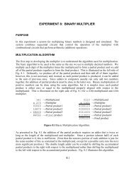
experiment 6: flip-flops and feedback devices - The Circuits and ...
experiment 6: flip-flops and feedback devices - The Circuits and ...
experiment 6: flip-flops and feedback devices - The Circuits and ...

Create successful ePaper yourself
Turn your PDF publications into a flip-book with our unique Google optimized e-Paper software.
PROCEDURE<br />
Before performing the procedures listed below, read the report section of the <strong>experiment</strong> to<br />
assure you make all required measurements <strong>and</strong> record all required data.<br />
A. Gated RS NOR Latch<br />
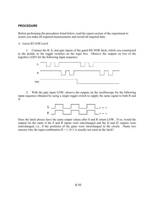
1. Connect the R, S, <strong>and</strong> gate inputs of the gated RS NOR latch, which you constructed<br />
in the prelab, to the toggle switches on the logic box. Observe the outputs on two of the<br />
logicbox LED's for the following input sequence:<br />
2. With the gate input LOW, observe the outputs on the oscilloscope for the following<br />
input sequence obtained by using a single toggle switch to supply the same signal to both R <strong>and</strong><br />
S:<br />
Does the latch always have the same output values after S <strong>and</strong> R return LOW. If so, would the<br />
outputs be the same if the S <strong>and</strong> R inputs were interchanged <strong>and</strong> the Q <strong>and</strong> Q' outputs were<br />
interchanged, i.e., if the positions of the gates were interchanged in the circuit. Name two<br />
reasons why the input combination R = 1, S=1 is usually not used on the latch?<br />
6.10