2D Mapping of Cluttered Indoor Environments by ... - ResearchGate
2D Mapping of Cluttered Indoor Environments by ... - ResearchGate
2D Mapping of Cluttered Indoor Environments by ... - ResearchGate

Create successful ePaper yourself
Turn your PDF publications into a flip-book with our unique Google optimized e-Paper software.
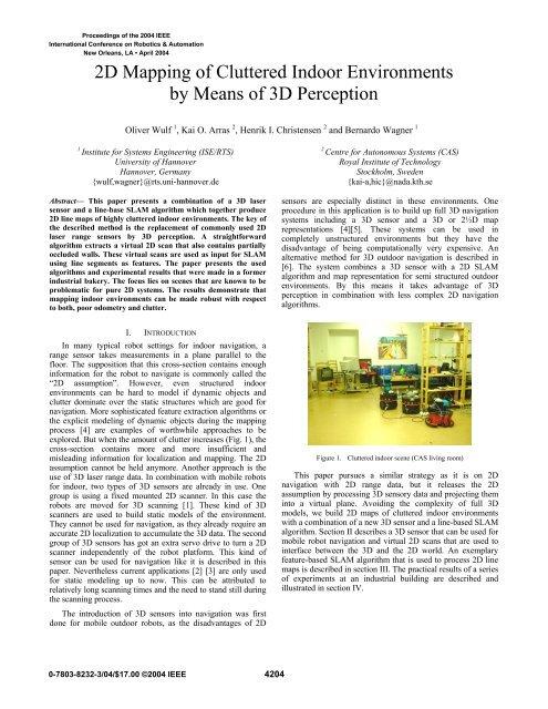
<strong>2D</strong> <strong>Mapping</strong> <strong>of</strong> <strong>Cluttered</strong> <strong>Indoor</strong> <strong>Environments</strong><br />
<strong>by</strong> Means <strong>of</strong> 3D Perception<br />
Oliver Wulf 1 , Kai O. Arras 2 , Henrik I. Christensen 2 and Bernardo Wagner 1<br />
1<br />
Institute for Systems Engineering (ISE/RTS)<br />
University <strong>of</strong> Hannover<br />
Hannover, Germany<br />
{wulf,wagner}@rts.uni-hannover.de<br />
Abstract— This paper presents a combination <strong>of</strong> a 3D laser<br />
sensor and a line-base SLAM algorithm which together produce<br />
<strong>2D</strong> line maps <strong>of</strong> highly cluttered indoor environments. The key <strong>of</strong><br />
the described method is the replacement <strong>of</strong> commonly used <strong>2D</strong><br />
laser range sensors <strong>by</strong> 3D perception. A straightforward<br />
algorithm extracts a virtual <strong>2D</strong> scan that also contains partially<br />
occluded walls. These virtual scans are used as input for SLAM<br />
using line segments as features. The paper presents the used<br />
algorithms and experimental results that were made in a former<br />
industrial bakery. The focus lies on scenes that are known to be<br />
problematic for pure <strong>2D</strong> systems. The results demonstrate that<br />
mapping indoor environments can be made robust with respect<br />
to both, poor odometry and clutter.<br />
2<br />
Centre for Autonomous Systems (CAS)<br />
Royal Institute <strong>of</strong> Technology<br />
Stockholm, Sweden<br />
{kai-a,hic}@nada.kth.se<br />
sensors are especially distinct in these environments. One<br />
procedure in this application is to build up full 3D navigation<br />
systems including a 3D sensor and a 3D or 2½D map<br />
representations [4][5]. These systems can be used in<br />
completely unstructured environments but they have the<br />
disadvantage <strong>of</strong> being computationally very expensive. An<br />
alternative method for 3D outdoor navigation is described in<br />
[6]. The system combines a 3D sensor with a <strong>2D</strong> SLAM<br />
algorithm and map representation for semi structured outdoor<br />
environments. By this means it takes advantage <strong>of</strong> 3D<br />
perception in combination with less complex <strong>2D</strong> navigation<br />
algorithms.<br />
I. INTRODUCTION<br />
In many typical robot settings for indoor navigation, a<br />
range sensor takes measurements in a plane parallel to the<br />
floor. The supposition that this cross-section contains enough<br />
information for the robot to navigate is commonly called the<br />
“<strong>2D</strong> assumption”. However, even structured indoor<br />
environments can be hard to model if dynamic objects and<br />
clutter dominate over the static structures which are good for<br />
navigation. More sophisticated feature extraction algorithms or<br />
the explicit modeling <strong>of</strong> dynamic objects during the mapping<br />
process [4] are examples <strong>of</strong> worthwhile approaches to be<br />
explored. But when the amount <strong>of</strong> clutter increases (Fig. 1), the<br />
cross-section contains more and more insufficient and<br />
misleading information for localization and mapping. The <strong>2D</strong><br />
assumption cannot be held anymore. Another approach is the<br />
use <strong>of</strong> 3D laser range data. In combination with mobile robots<br />
for indoor, two types <strong>of</strong> 3D sensors are already in use. One<br />
group is using a fixed mounted <strong>2D</strong> scanner. In this case the<br />
robots are moved for 3D scanning [1]. These kind <strong>of</strong> 3D<br />
scanners are used to build static models <strong>of</strong> the environment.<br />
They cannot be used for navigation, as they already require an<br />
accurate <strong>2D</strong> localization to accumulate the 3D data. The second<br />
group <strong>of</strong> 3D sensors has got an extra servo drive to turn a <strong>2D</strong><br />
scanner independently <strong>of</strong> the robot platform. This kind <strong>of</strong><br />
sensor can be used for navigation like it is described in this<br />
paper. Nevertheless current applications [2] [3] are only used<br />
for static modeling up to now. This can be attributed to<br />
relatively long scanning times and the need to stand still during<br />
the scanning process.<br />
The introduction <strong>of</strong> 3D sensors into navigation was first<br />
done for mobile outdoor robots, as the disadvantages <strong>of</strong> <strong>2D</strong><br />
Figure 1. <strong>Cluttered</strong> indoor scene (CAS living room)<br />
This paper pursues a similar strategy as it is on <strong>2D</strong><br />
navigation with <strong>2D</strong> range data, but it releases the <strong>2D</strong><br />
assumption <strong>by</strong> processing 3D sensory data and projecting them<br />
into a virtual plane. Avoiding the complexity <strong>of</strong> full 3D<br />
models, we build <strong>2D</strong> maps <strong>of</strong> cluttered indoor environments<br />
with a combination <strong>of</strong> a new 3D sensor and a line-based SLAM<br />
algorithm. Section II describes a 3D sensor that can be used for<br />
mobile robot navigation and virtual <strong>2D</strong> scans that are used to<br />
interface between the 3D and the <strong>2D</strong> world. An exemplary<br />
feature-based SLAM algorithm that is used to process <strong>2D</strong> line<br />
maps is described in section III. The practical results <strong>of</strong> a series<br />
<strong>of</strong> experiments at an industrial building are described and<br />
illustrated in section IV.
II.<br />
3D PERCEPTION<br />
The 3D perception system that is described in this paper<br />
consists <strong>of</strong> two parts. The first is a fast 3D laser range sensor<br />
that is especially adapted for use on mobile robots. This<br />
scanner is described in section IIa. The second part is a<br />
construction called virtual <strong>2D</strong> scans. Section IIb will introduce<br />
these virtual scans and will also present an algorithm that is<br />
able to extract them out <strong>of</strong> 3D point-clouds.<br />
A. Fast 3D Laser Range Scans<br />
As there is no commercial 3D laser range scanner available<br />
which could be used for mobile robots, it is common practice<br />
to assemble 3D sensors out <strong>of</strong> a standard <strong>2D</strong> scanner and an<br />
additional servo drive [7]. A scanner that is used in our system<br />
is the SICK LMS 291 in combination with a self-build servo<br />
drive (scan drive). Different orientations <strong>of</strong> the <strong>2D</strong> scanner in<br />
combination with different turning axis result in a number <strong>of</strong><br />
possible scanning patterns. Two scanning patterns that are<br />
practicable for our application are the yawing scan, vertical <strong>2D</strong><br />
raw scan and rotation around the upright axis (see Fig. 2a), and<br />
the yawing scan top, <strong>2D</strong> raw scan facing up and rotation<br />
around the upright axis (see Fig. 2b). The yawing scan pattern<br />
results in the maximal possible field <strong>of</strong> view <strong>of</strong> 360° horizontal<br />
and 180° vertical. The yawing scan top has got also a<br />
horizontal opening angle <strong>of</strong> 360° but it covers only the upper<br />
hemisphere. For this reason a sensor with such a scanning<br />
pattern is not able to detect obstacles that lie on the ground. On<br />
the other hand the data is sufficient for localization and<br />
mapping and the scan time, which is half <strong>of</strong> the yawing scan<br />
time, is attractive for faster motion.<br />
(a) (b)<br />
Figure 2. Continuously turning 3D scanner:<br />
(a) yawing scan, (b) yawing scan top<br />
Short scanning times and the ability to scan while moving<br />
are the main criteria that decide on the usability <strong>of</strong> 3D scanners<br />
for navigation tasks. For this reason the sensor that is used in<br />
this paper contains a number <strong>of</strong> improvements. One<br />
mechanical improvement is the ability <strong>of</strong> the scan drive to turn<br />
continuously, which is implemented <strong>by</strong> using slip rings for<br />
power and data connection to the <strong>2D</strong> scanner. This leads to a<br />
homogeneous distribution <strong>of</strong> scan points and saves the energy<br />
and time that is needed for acceleration and deceleration <strong>of</strong><br />
panning scanners. Another improvement that becomes<br />
important with short scanning times <strong>of</strong> a few seconds is the<br />
compensation <strong>of</strong> systematic measurement errors. This<br />
compensation is done <strong>by</strong> means <strong>of</strong> sensor analysis and hard<br />
real-time synchronization and time stamping. The result <strong>of</strong><br />
these optimizations that are described in detail in [7] lead to<br />
scan times as short as 4.8s for a yawing scan with 1° horizontal<br />
and 1° vertical resolution (see Fig. 3), 2.4s for a 2°, 1° yawing<br />
scan or a 1°, 1° yawing scan top or only 1.2s for a yawing scan<br />
top with 2°, 1° resolution. Another feature is the ability to scan<br />
while driving, which is achieved with a move compensation<br />
algorithm [6]. This algorithm is using a 3D dead-reckoning<br />
mechanism that combines wheel odometry and a gyroscope.<br />
The estimated robot position is used to transform the 3D pointcloud<br />
into a world fixed and therefore undistorted coordinate<br />
frame.<br />
Figure 3.<br />
3D point-cloud yawing scan 1°, 1°<br />
B. Virtual <strong>2D</strong> Scans<br />
The 3D point-clouds that are acquired <strong>by</strong> the 3D scanner<br />
contain detailed information about the surrounding<br />
environment. Because 3D point-clouds are raw data<br />
representations, they include redundant information and many<br />
measurement points which are not needed for localization and<br />
mapping. Approaches which use this raw data for scan<br />
matching and full 3D modeling are computational very<br />
expensive. If the goal is to localize or navigate a mobile robot,<br />
these full 3D algorithms are not efficient. The use <strong>of</strong> virtual <strong>2D</strong><br />
scans is more efficient here as it aims to reduce the amount <strong>of</strong><br />
data without loosing information that is essential for mobile<br />
robot localization. The reduced data sets can afterwards be<br />
used for computationally less expensive matching and SLAM<br />
algorithms. The data representation that is chosen <strong>of</strong> virtual <strong>2D</strong><br />
scans is similar to the data that can be measured directly with a<br />
<strong>2D</strong> laser range sensor. It is defined as a number <strong>of</strong> object<br />
surface points that are given in a <strong>2D</strong> robot coordinate system.<br />
For this reason existing <strong>2D</strong> scanners can be replaced <strong>by</strong> more<br />
intelligent 3D perception systems and can be used <strong>by</strong> keeping<br />
existing <strong>2D</strong> SLAM algorithms.<br />
These intelligent sensors are based on algorithms that are<br />
able to extract the information that is essential for SLAM out<br />
<strong>of</strong> 3D point-clouds. This paper describes a first,<br />
straightforward, heuristic that extracts virtual scans from<br />
cluttered indoor scenes. Objects that are preferably used for<br />
indoor localization are walls because they are immobile and<br />
efficiently modeled as lines. The first step to create this virtual<br />
<strong>2D</strong> scan is to project all 3D points onto the plane <strong>by</strong> setting the
z-coordinate to zero. A virtual <strong>2D</strong> scan that contains primarily<br />
walls can thereafter be assembled <strong>by</strong> taking one point out <strong>of</strong><br />
each vertical raw scan (resp. two points for a yawing scan top).<br />
This point is chosen to be the one with the largest distant to the<br />
center <strong>of</strong> the robot. As walls build the boundary <strong>of</strong> a closed<br />
indoor scene the chosen point is most probably a wall point. By<br />
this means points lying on the floor, ceiling or on obstacles are<br />
filtered out. The thus generated <strong>2D</strong> scan is only disturbed <strong>by</strong><br />
open doors, windows and objects that cover the wall<br />
completely. Fig. 4 shows a virtual <strong>2D</strong> scan <strong>of</strong> the CAS living<br />
room in comparison to a regular <strong>2D</strong> range scan taken at 50cm<br />
height. A photograph and one view <strong>of</strong> the 3D point-cloud from<br />
the same room can be seen in Fig. 1 and Fig. 3.<br />
Figure 4.<br />
Virtual <strong>2D</strong> scan (black), Regular <strong>2D</strong> scan (50cm height, red)<br />
III.<br />
LINE-BASED SLAM<br />
This section describes the line-based SLAM algorithm which<br />
has been employed for the experiments. Assuming that the<br />
reader is familiar with the standard SLAM framework as<br />
initially proposed <strong>by</strong> [8], [9] we will focus on the particularity<br />
<strong>of</strong> our method.<br />
A. Feature Representation<br />
When lines are used as landmarks for SLAM the<br />
representation problem <strong>of</strong> uncertain features becomes visible.<br />
Several line models have shortcomings when used for SLAM<br />
such as the Hessian (alpha, r)-representation whose error<br />
propagation across frame transforms leads to physically<br />
meaningless covariance matrices. Here we use the SPmodel<br />
[10] to represent line segments. In the SPmodel, a reference<br />
frame is attached <strong>by</strong> default to each feature regardless its type.<br />
Errors are represented locally in that frame and in case <strong>of</strong> a<br />
non-full pose feature (e.g. lines or (x,y)-points) the so called<br />
binding matrix selects those rows in the feature state vector<br />
that “make sense” for the given feature type.<br />
To represent finite line segments, the segment endpoints are<br />
expressed relative to the frame <strong>of</strong> the supporting line as single<br />
rank (i.e. one dimensional) locations with a constant<br />
uncorrelated typical uncertainty.<br />
B. Robot Displacement<br />
A differential drive configuration is used as the kinematic<br />
model for the robot. This simplification allows us to apply an<br />
uncertainty model that models non-systematic odometry errors<br />
(correctly) in the wheel space and not in the Cartesian space<br />
[11]. From the odometry data delivered <strong>by</strong> the wheel encoders<br />
for the robot x- and y-position and the IMU device for the<br />
vehicle orientation, the encoder values for the left and right<br />
wheel are determined and taken as inputs for the kinematic<br />
model. Given a higher frequency odometry update with<br />
respect to the rate <strong>of</strong> the observations, a recursive formulation<br />
yields the sought process model Jacobian. This Jacobian is<br />
needed to update the first row and column <strong>of</strong> the map<br />
covariance matrix during the state prediction step.<br />
C. Observation<br />
The line extraction algorithm from [12] has been used. It uses<br />
a sliding window technique and fit expressions that minimizes<br />
weighted squared errors perpendicular from the points onto<br />
the line. Its complexity is O(n*n w ) where n is the number <strong>of</strong><br />
scan points, n w the size <strong>of</strong> the window and n w
is a servo drive that is especially constructed for fast and<br />
continuous scanning. A scalable processing box (SPB [13])<br />
that is based on an embedded-PC with Linux/RTAI real-time<br />
operating system is doing the 3D scanning and data acquisition.<br />
The ATRV onboard unit and the SPB are interconnected via<br />
CAN-Bus.<br />
The mapping experiments were carried out with a remote<br />
controlled robot driving at about 0.1m/s. The 3D scanner is set<br />
up to measure full 180°x360° range scans with a resolution <strong>of</strong><br />
1°x1°. That results in a scan time <strong>of</strong> 4.8s. With the robot<br />
driving at the given speed the 3D scanner is able to measure<br />
one 3D scan, respectively one virtual <strong>2D</strong> scan, about every<br />
0.5m.<br />
Within these first experiments, all 3D data processing and<br />
SLAM is done <strong>of</strong>fline in a MATLAB environment.<br />
scan. This removes a vast <strong>of</strong> obstacles. Only obstacles that<br />
fully occlude the wall, e.g. people walking closely to the robot<br />
cannot be removed. As the virtual <strong>2D</strong> scan contains mostly<br />
wall points it turns out to be ideal input data for the following<br />
<strong>2D</strong> algorithms. The output is comparable with a <strong>2D</strong> scan taken<br />
in an empty room or corridor.<br />
Fig. 6 shows a clipping <strong>of</strong> a typical scene in a corridor. In<br />
this case two persons, a ladder, open cupboard doors and<br />
several other obstacles occlude the corridor. As it can be seen<br />
in the lower part <strong>of</strong> Fig. 6, a normal <strong>2D</strong> scan (red points)<br />
contains many measurement points on these obstacles in<br />
contrast to the virtual <strong>2D</strong> scan (black points) that represents<br />
large parts <strong>of</strong> the walls.<br />
Figure 5.<br />
Experiments in a former industrial bakery<br />
B. Test Environment<br />
A large indoor environment that was used as an industrial<br />
bakery before has been available for the experiments described<br />
in this paper is. Currently it is used as a training site <strong>by</strong><br />
Swedish military, police and fire brigades.<br />
The experiments covered two test areas <strong>of</strong> 20x30m and<br />
30x30m with a number is interconnected rooms. The rooms<br />
have got a flat floor, but there are several steps between rooms.<br />
Though they are traversable with the ATRV, they lead to large<br />
odometry errors. A lot <strong>of</strong> pipes and electrical installations are<br />
mounted on the walls and on the ceiling (see Fig. 5). Various<br />
obstacles and 6 people were in the test area during the<br />
experiment. Especially because <strong>of</strong> the occluded walls the test<br />
area is known to be problematic for pure <strong>2D</strong> mapping.<br />
C. Results<br />
The algorithm that is used to process virtual <strong>2D</strong> scans was<br />
applied to all 208 3D point-clouds out <strong>of</strong> both test runs. The<br />
experiments show very good and stabile results for wall<br />
extraction in closed indoor scenes. This can be traced back to<br />
the fact that only one correct wall point per vertical <strong>2D</strong> scan is<br />
needed to produce a correct representation in the virtual <strong>2D</strong><br />
Figure 6. Experimental data <strong>of</strong> cluttered corridor<br />
The algorithm was applied to build two maps. The first run,<br />
revisiting the start point twice, consists <strong>of</strong> 156 steps and<br />
results in a map with 103 landmarks (Fig. 7a & 7b). The<br />
second run, starting in a big hall, has 72 steps and yields a map<br />
with 126 features (Fig. 8a & 8b).<br />
In addition to the clutter in the test environment, two<br />
circumstances made localization and mapping more difficult.<br />
On reason is the large odometry drift <strong>of</strong> the skid steering
(a) (b)<br />
Figure 7. <strong>Mapping</strong> experiment 1: (a) virtual <strong>2D</strong> scan and odometry,<br />
(b) line-based map calculated <strong>by</strong> SLAM algorithm<br />
platform. The second difficulty is the lower data rate <strong>of</strong> virtual<br />
<strong>2D</strong> scans in comparison to standard <strong>2D</strong> sensors. In our<br />
experiments the observations are made about every 0.5m.<br />
In spite <strong>of</strong> that the SLAM algorithm was able to calculate<br />
consistent maps for both test runs. This robustness can be<br />
attributed to the use <strong>of</strong> virtual <strong>2D</strong> scans. The 360° opening<br />
angle <strong>of</strong> the scanner allows the complete observation <strong>of</strong> the<br />
surrounding. This is especially useful while passing doors, as<br />
features in the old room and in the new room can be seen in<br />
the same scan. Another essential fact benefit is the ability to<br />
observe also partially occluded walls. This contributes to the<br />
localization and mapping process as it provides landmarks that<br />
cannot be seen with a <strong>2D</strong> sensor. The fact that obstacles and<br />
clutter are mostly removed from virtual <strong>2D</strong> scans allows<br />
having more confidence in the sensed observation. For this<br />
reason the SLAM algorithm needs less observations to add a<br />
new feature into the map correctly.<br />
We further observe an over-segmententation <strong>of</strong> the map. Walls<br />
are modeled <strong>by</strong> several, sometimes overlapping segments<br />
where one long segment could be expected. This type <strong>of</strong><br />
inconsistency in the description <strong>of</strong> the environment is typical<br />
for single-segment features and has been observed in [10] and<br />
[12]. As this problem is already known from pure <strong>2D</strong> system it<br />
cannot be led back to the new 3D perception.<br />
V.<br />
CONCLUSION<br />
This paper presented a novel method for robust localization<br />
and mapping <strong>of</strong> cluttered indoor environments. The new ability<br />
to model cluttered environments with line-feature maps is<br />
gained <strong>by</strong> the use <strong>of</strong> 3D perception. We introduced an<br />
algorithm to extract virtual <strong>2D</strong> scans from full 3D laser range<br />
data. These virtual <strong>2D</strong> scans that contain mainly static wall<br />
points are used as input data for a <strong>2D</strong> line-based SLAM<br />
algorithm. By this means we presented an effective<br />
combination <strong>of</strong> rich 3D perception and efficient <strong>2D</strong> localization<br />
and mapping. The applicability <strong>of</strong> this new method was<br />
demonstrated <strong>by</strong> experiments within industrial indoor<br />
environments.<br />
ACKNOWLEDGMENT<br />
The work described is part <strong>of</strong> a collaboration within the<br />
project MoRob (Modular Educational Robotic Toolbox), which<br />
is funded <strong>by</strong> the Swedish Wallenberg Foundation, the German<br />
Federal Ministry <strong>of</strong> Education and Research and the Research<br />
Ministry <strong>of</strong> Lower Saxony. Furthermore the authors would like<br />
to thank John Folkesson, Andreas Hedstrom, Patric Jensfelt,<br />
and Carl Lundberg for their help with the bakery experiments.
(a) (b)<br />
Figure 8. <strong>Mapping</strong> experiment 2: (a) virtual <strong>2D</strong> scan and odometry,<br />
(b) line-based map calculated <strong>by</strong> SLAM algorithm<br />
REFERENCES<br />
[1] J. Weingarten, G. Grüner, and R. Siegwart, “A Fast and Robust 3D<br />
Feature Extraction Algorithm for Structured Environment<br />
Reconstruction”, International Conference on Advanced Robotics,<br />
Coimbra, Portugal, July 2003.<br />
[2] H. Surmann, K. Lingemann, A. Nüchter, and J. Hertzberg, “A 3D Laser<br />
Range Finder for Autonomous Mobile Robots”, International<br />
Symposium on Robotics, Zurich, Switzerland, April 2001.<br />
[3] D. Hähnel, and W. Burgard, “Map Building with Mobile Robots in<br />
Populated <strong>Environments</strong>”, IEEE/RSJ Conference on Intelligent Robots<br />
and Systems, Lausanne, Switzerland, September 2002.<br />
[4] S. Lacroix, A. Mallet, D. Bonnafous, G. Bauzil; S. Fleury, M. Herrb,<br />
and R. Chatila, “Autonomous Rover Navigation on Unknown Terrains:<br />
Functions and Integration”, International Journal <strong>of</strong> Robotics Research,<br />
vol. 21, issue 10, October 2002.<br />
[5] P. Bellutta, R. Manduchi, L. Matthies, and K. Owens, “Terrain<br />
Perception for Demo III”, IEEE Intelligent Vehicle Symposium,<br />
Dearborn, USA, October 2000.<br />
[6] C. Brenneke, O. Wulf, and B. Wagner, “Using 3D Laser Range Data for<br />
SLAM in Outdoor <strong>Environments</strong>”, IEEE/RSJ Conference on Intelligent<br />
Robots and Systems, Las Vegas, USA, October 2003.<br />
[7] O. Wulf, and B. Wagner, “Fast 3D Scanning Methods for Laser<br />
Measurement Systems”, International Conference on Control Systems<br />
and Computer Science, Bucharest, Romania, July 2003.<br />
[8] P. Moutarlier, and R. Chatila, “Stochastic Multisensory Data Fusion For<br />
Mobile Robot Location and Environmental Modelling”, International<br />
Symposium on Robotics Research, 1990.<br />
[9] R. Smith, M. Self, and P. Cheeseman, “A Stochastic Map for Uncertain<br />
Spatial Relationships”, 4th International Symposium on Robotics<br />
Research, 1987.<br />
[10] J.A. Castellanos, and J.D. Tardos, “Mobile Robot Localization and Map<br />
Building: A Multisensor Fusion Approach”, Kluwer, 1999.<br />
[11] K.S. Chong, and L. Kleeman, “Accurate Odometry and Error Modelling<br />
for a Mobile Robot”, IEEE International Conference on Robotics and<br />
Automation, Albuquerque, USA, 1997.<br />
[12] K.O. Arras, “Feature-Based Robot Navigation in Known and Unknown<br />
Environment”, PhD Dissertation N° 2765, Swiss Federal Institute <strong>of</strong><br />
Technology Lausanne, Autonomous Systems Lab, June 2003.<br />
[13] P. Hohmann, U.Gerecke, and B. Wagner, “A Scalable Processing Box<br />
for Systems Engineering Teaching with Robotics”, International<br />
Conference on Systems Engineering, Coventry, UK, 2003.