betriebsanleitung operating instructions speck-triplex-plungerpumpe ...
betriebsanleitung operating instructions speck-triplex-plungerpumpe ...
betriebsanleitung operating instructions speck-triplex-plungerpumpe ...

Create successful ePaper yourself
Turn your PDF publications into a flip-book with our unique Google optimized e-Paper software.
BETRIEBSANLEITUNG<br />
OPERATING INSTRUCTIONS<br />
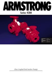
SPECK-TRIPLEX-PLUNGERPUMPE<br />
SPECK-TRIPLEX-PLUNGER PUMP<br />
P31/25-220<br />
P30/36-150<br />
P30/43-130<br />
Leistungsbereich - Performance<br />
Code No.<br />
Power<br />
Consump.<br />
Überdruck<br />
max.<br />
Pressure<br />
max.<br />
Drehzahl<br />
max.<br />
RPM<br />
max.<br />
Type Best.-Nr. Leistungsaufnahme<br />
Fördermenge<br />
max.<br />
Output<br />
max.<br />
Wasser<br />
temp.<br />
max.<br />
Water-<br />
Temp.<br />
max.<br />
Plunger<br />
-Ø<br />
Plunger<br />
dia.<br />
Hub<br />
Gewicht<br />
ca.<br />
Stroke Weight<br />
approx.<br />
NPSHR<br />
NPSH<br />
Required<br />
kW bar min -1 l/min °C mm mm kg mWs<br />
P31/25-220 00.0559 11.0 220 1420 25.2 70 20 20 19.0 6.5<br />
P30/36-150 00.0741 11.0 150 1420 36.2 70 24 20 19.0 7.8<br />
P30/43-130 00.0742 11.0 130 1420 42.5 70 26 20 19.0 8.6<br />
NPSH erf. ist gültig für Wasser (spez. Gewicht 1kg/dm 3 , Viskosität<br />
=1°E) bei max. zulässiger Pumpendrehzahl.<br />
Inbetriebnahme und Wartung<br />
Vor Inbetriebnahme Ölstand prüfen und für störungsfreien<br />
Wasserzulauf sorgen.<br />
Ölfüllmenge 0.7l. Nur Getriebeöl ISO VG 220 GL4 (z.B. Aral Degol<br />
BG220) oder KFZ- Getriebeöl SAE 90 GL4 verwenden.<br />
Erster Ölwechsel nach 50 Betriebsstunden; dann alle 500<br />
Betriebsstunden, spätestens jedoch nach 6 Monaten. Achtung bei<br />
Betrieb in feuchten Räumen bzw. bei hohen<br />
Temperaturschwankungen. Bei Kondenswasserbildung im<br />
Getrieberaum (Aufschäumen des Öles) sofort Ölwechsel durchführen.<br />
NPSH-Wert beachten.<br />
Max. Zulaufdruck 10 bar, max. Saughöhe -0.3 bar.<br />
Required NPSH refers to water: Spezific weight 1kg/dm 3 , viscosity 1°E<br />
at max. permissible revolutions.<br />
Operation and Maintenance<br />
Check oil level prior to starting and ensure trouble-free water supply.<br />
Oil: Use only 0.7 litres of ISO VG 220 GL4 (e.g. Aral Degol BG220) or<br />
SAE 90 GL4 gear oil.<br />
Initial change after 50 <strong>operating</strong> hours and then every 500 <strong>operating</strong><br />
hours, after 6 months operation in any case.<br />
Caution when <strong>operating</strong> in damp places or with high temperature<br />
fluctuations. Oil must be changed immediately, should condensate<br />
(frothy oil) occur in the gear box.<br />
Keep NPSH under control.<br />
Max. input pressure 10 bar, max. suction head -0.3 bar.<br />
Sicherheitsvorschriften<br />
Es ist ein Sicherheitsventil gemäß den “Richtlinien für<br />
Flüssigkeitsstrahler” vorzusehen, das so eingestellt ist, dass der<br />
Betriebsdruck um nicht mehr als 10% überschritten werden kann.<br />
Bei Nichteinhaltung dieser Vorschrift sowie bei Überschreiten der<br />
Temperatur- und Drehzahlgrenze erlischt jegliche Garantie.<br />
Beim Betrieb der Pumpe muss das freie Wellenende durch den<br />
Wellenschutz (17), die angetriebene Wellenseite und Kupplung durch<br />
einen bauseitigen Berührungsschutz abgedeckt sein.<br />
Vor Wartungsarbeiten an Pumpe und Anlage muss sichergestellt<br />
werden, dass Druckleitung und Pumpe drucklos sind! Saugleitung<br />
verschließen.<br />
Versehentliches Starten des Antriebsmotors durch geeignete<br />
Maßnahmen vermeiden (Sicherungen herausschrauben).<br />
Vor Inbetriebnahme Pumpe und druckseitige Anlagenteile drucklos<br />
entlüften. Ansaugen und Fördern von Luft oder Luft-Wassergemisch<br />
sowie Kavitation unbedingt vermeiden.<br />
Kavitation bzw. Kompression von Gasen führt zu<br />
unkontrollierbaren Druckstössen und kann Pumpen- und<br />
Anlagenteile zerstören sowie Bedienungspersonal gefährden!<br />
SPECK-TRIPLEX-Pumpen sind geeignet zur Förderung von sauberem<br />
Wasser oder anderen nicht aggressiven oder abrassiven Medien mit<br />
ähnlichem spezifischen Gewicht wie Wasser.<br />
Werden andere Flüssigkeiten, insbesondere brennbare, explosive<br />
und toxische Medien gefördert, so ist eine Rücksprache mit dem<br />
Pumpenhersteller hinsichtlich der Materialbeständigkeiten<br />
unbedingt erforderlich. Die Einhaltung der entsprechenden<br />
Sicherheitsvorschriften ist durch den Gerätehersteller bzw. durch<br />
den Anwender sicherzustellen.<br />
Safety Rules<br />
Pump operation without safety valve as well as any excess in<br />
temperature or speed limits automatically voids the warranty. The<br />
safety valve must be regulated in accordance with the guidelines for<br />
liquid spraying units so that the admissible <strong>operating</strong> pressure can not<br />
be exceeded by more than 10%.<br />
When the pump is in operation, the open shaft end must be covered up<br />
by shaft protector (17), the driven shaft side and coupling by a contactprotector.<br />
Pressure in discharge line and in pump must be at zero before any<br />
maintenance to the pump takes place. Close up suction line.<br />
Disconnect fuses to ensure that the driving motor does not get<br />
switched on accidently.<br />
Make sure that all parts on the pressure side of the unit are vented and<br />
refilled, with pressure at zero, before starting the pump.<br />
In order to prevent air, or an air/water-mixture being absorbed and to<br />
prevent cavitation occurring, the pump-NPSHR, positive suction head<br />
and water temperature must be kept under control.<br />
Cavitation and/or compression of gases lead to uncontrollable<br />
pressure-kicks which can ruin pump and unit parts and also be<br />
dangerous to the operator or anyone standing nearby.<br />
SPECK TRIPLEX Plunger Pumps are suitable for pumping clean water<br />
and other non-agressive or abrasive media with a specific weight<br />
similar to water.<br />
Before pumping other liquids - especially inflammable, explosive<br />
and toxic media - the pump manufacturer must under all<br />
circumstances be consulted with regard to the resistance of the<br />
pump material. It is the responsibility of the equipment<br />
manufacture and/or operator to ensure that all pertinent safety<br />
regulations are adhered to.
Ersatzteilverzeichnis P31/25-220 Best.-Nr.: 00.0559<br />
Spare Parts List P30/36-150 Code Nr. 00.0741<br />
P30/43-130 00.0742<br />
Lfd. Nr. Stückzahl Best.-Nr. Benennung Description<br />
Item No. No. Off Code No.<br />
1 1 01.0255 Antriebsgehäuse Crankcase<br />
2 1 00.2431 Ölauffüllstopfen kpl. Oil Filler Plug Assy<br />
3 1 03.0162 Getriebedeckel Crankcase Cover<br />
4 1 06.0286 O-Ring zu 3 O-Ring for 3<br />
5 1 00.0564 Ölmeßstab kpl. Oil Dipstick Assy<br />
6 1 06.0053 O-Ring zu 5 O-Ring for 5<br />
7 1 00.2416 Ölschauglas Oil Sight Glass<br />
9 4 21.0026 Zylinderschraube Cylinder Screw<br />
10 4 07.2994 Federring Spring Ring<br />
11 2 07.0705 Stopfen G1/2 Plug G1/2<br />
11A 2 06.0282 Dichtung Seal<br />
12 2 03.0163 Lagerdeckel Bearing Cover<br />
13 2 06.0288 O-Ring O-Ring<br />
14 2 06.0287 Radialwellendichtring Radial Shaft Seal<br />
15 2 05.0100 Zylinderrollenlager Roller Bearing<br />
15A 1 07.1961 Paßscheibe Fitting Disc<br />
15B 1 07.0859 Paßscheibe Fitting Disc<br />
16 6 21.0034 Sechskantschraube Hexagon Screw<br />
17 1 07.0913 Wellenschutz Shaft Protector<br />
18 1 11.0258 Kurbelwelle Crankshaft<br />
19 1 07.0861 Scheibenfeder Woodruff Key<br />
20 3 00.3288 Gleitlagerpleuel kpl. Connecting Rod Assy<br />
22 3 00.0596 Kreuzkopf kpl. Crosshead Assy<br />
23 3 11.0259 Kreuzkopfbolzen Crosshead Pin<br />
24A 3 11.0269 Plungerrohr (P31/25) Plunger Pipe (P31/25)<br />
24A 3 11.0271 Plungerrohr (P30/36) Plunger Pipe (P30/36)<br />
24A 3 11.0272 Plungerrohr (P30/43) Plunger Pipe (P30/43)<br />
24B 3 21.0076 Spannschraube Tension Screw<br />
24C 3 06.0113 O-Ring O-Ring<br />
24D 3 06.0114 Stützring Support Ring<br />
24E 3 06.0275 Cu-Dichtring Copper Ring<br />
25 3 07.0955 Ölabstreifer Oil Scraper<br />
26 3 06.0290 Radialwellendichtring Radial Shaft Seal<br />
28 2 07.0874 Zentrierhülse Seal Retainer<br />
29 1 01.0272 Ventilgehäuse (P30/36, P30/43) Valve Casing (P30/36, P30/43)<br />
29 1 01.0424 Ventilgehäuse (P31/25) Valve Casing (P31/25)<br />
30 3 07.0921 Druckring (P31/25) Pressure Ring (P31/25)<br />
30 3 07.0923 Druckring (P30/36) Pressure Ring (P30/36)<br />
30 3 07.0924 Druckring (P30/43) Pressure Ring (P30/43)<br />
•31 3 06.0295 Manschette (P31/25) Sleeve (P31/25)<br />
o31 3 06.0297 Manschette (P30/36) Sleeve (P30/36)<br />
+31 3 06.0298 Manschette (P30/43) Sleeve (P30/43)<br />
32 3 07.0927 Manschettenstützring (P31/25) Sleeve Support Ring (P31/25)<br />
32 3 07.0929 Manschettenstützring (P30/36) Sleeve Support Ring (P30/36)<br />
32 3 07.0930 Manschettenstützring (P30/43) Sleeve Support Ring (P30/43)<br />
33 3 07.0933 Druckfeder (P31/25) Pressure Spring (P31/25)<br />
33 3 07.0918 Druckfeder (P30/36, P30/43) Pressure Spring (P30/36, P30/43)<br />
••34 3 07.0956 Federspannschale Druck Spring Tension Cap for Pressure<br />
••34A 3 07.1990 Federspannschale Saug Spring Tension Cap for Suction<br />
••35 6 07.2147 Ventilfeder Valve Spring<br />
••36 6 07.0957 Ventilplatte Valve Plate<br />
••37 6 07.0292 Ventilsitz Valve Seat<br />
••38 6 06.0067 O-Ring O-Ring<br />
39 3 07.1444 Saugventilaufnahme (P31/25) Suction Valve Adaptor (P31/25)<br />
39 3 07.0915 Saugventilaufnahme (P30/36, P30/43) Suction Valve Adaptor (P30/36, P30/43)<br />
39A 3 07.0916 Distanzring Spacer Ring<br />
•o+40 3 06.0255 O-Ring O-Ring<br />
41 3 07.0912 Stopfen M36x1.5 Plug M36x1.5<br />
•o+42 3 06.0285 O-Ring O-Ring<br />
43 3 07.2849 Stopfen G3/4 (P31/25) Plug G3/4 (P31/25)<br />
43 3 07.0814 Stopfen M30x1.5 (P30/36, P30/43) Plug G3/4 (P30/36, P30/43)<br />
o+44 3 06.0251 O-Ring (P30/36, P30/43) O-Ring (P30/36, P30/43)<br />
•44 3 06.0496 O-Ring (P31/25) O-Ring (P31/25)<br />
45 4 21.0074 Stiftschraube Stud Bolt<br />
46 4 07.0988 Sechskantmutter Hexagon Nut<br />
47 4 07.2707 Scheibe Disc<br />
48 1 01.0262 Zwischengehäuse (P31/25) Intermediate Casing (P31/25)<br />
48 1 01.0264 Zwischengehäuse (P30/36) Intermediate Casing (P30/36)<br />
48 1 01.0265 Zwischengehäuse (P30/43) Intermediate Casing (P30/43)<br />
•o+49 1 06.0304 O-Ring O-Ring<br />
•50 3 06.0112 Manschette (P31/25) Sleeve (P31/25)<br />
o50 3 06.0301 Manschette (P30/36) Sleeve (P30/36)<br />
+50 3 06.0298 Manschette (P30/43) Sleeve (P30/43)<br />
51 3 07.1432 Stützring (P31/25) Support Ring (P31/25)<br />
51 3 07.0959 Stützring (P30/36) Support Ring (P30/36)<br />
51 3 07.0960 Stützring (P30/43) Support Ring (P30/43)<br />
52 1 07.0705 Stopfen G1/2 Plug G1/2<br />
53 1 07.1001 Stopfen G3/4 Plug G3/4<br />
1 00.1982 Antrieb kpl. (P31/25) Gear Assy (P31/25)<br />
1 00.1984 Antrieb kpl. (P30/36) Gear Assy (P30/36)<br />
1 00.1985 Antrieb kpl. (P30/43) Gear Assy (P30/43)<br />
1 00.0794 Pumpenkopf kpl. (P31/25) Pump Head Assy (P31/25)<br />
1 00.0792 Pumpenkopf kpl. (P30/36) Pump Head Assy (P30/36)<br />
1 00.0793 Pumpenkopf kpl. (P30/43) Pump Head Assy (P30/43)<br />
• 1 14.0038 Rep. Satz Dichtungen (P31/25) Seal Repair Kit (P31/25)<br />
o 1 14.0040 Rep. Satz Dichtungen (P30/36) Seal Repair Kit (P30/36)<br />
+ 1 14.0041 Rep. Satz Dichtungen (P30/43) Seal Repair Kit (P30/43)<br />
•• 1 14.0037 Rep. Satz Ventile Valve Repair Kit<br />
Bei Bestellung von Ersatzteilen bitte Bestell-Nr., Pumpen-Nr. und -type angeben<br />
When ordering please state Code No., Pump Model and Pump Serial No.
Technische Änderungen vorbehalten<br />
Subject to change<br />
P30 / P31
Ventile überprüfen<br />
Instandsetzung<br />
Saugventil: Stopfen (41) herausschrauben. Saugventilaufnahme (39)<br />
mit Saugventil herausziehen. Ventilbauteile mit weichem Werkzeug<br />
aus der Saugventilaufnahme herausdrücken. Teile überprüfen,<br />
verschlissene Teile austauschen.<br />
O-Ringe (38, 40, 42) überprüfen und ggf. austauschen.<br />
Druckventil: Stopfen (43) herausschrauben. Beim darrunterliegenden<br />
Druckventil Federspannschale (34), Ventilfeder (35) und Ventilplatte<br />
(36) herausnehmen. Ventilsitz (37) mittels Innenauszieher Gr.2<br />
herausziehen.<br />
Teile überprüfen, verschlissene Teile austauschen. O-Ringe (38, 44)<br />
überprüfen und ggf. austauschen.<br />
Stopfen (41, 43) mit 70Nm (P31/25 mit 80Nm) festziehen.<br />
Dichtungen und Plungerrohr überprüfen:<br />
Stopfen (41) herausschrauben. Muttern (46) lösen und Ventilgehäuse<br />
über die Plunger nach vorne abziehen. Saugventilaufnahme (39),<br />
Spannfeder (33) und Dichtungseinheit (30, 31, 32) herausnehmen.<br />
Plungerrohroberflächen prüfen, beschädigte Oberflächen führen zu<br />
hohem Dichtungsverschleiß.<br />
Bei Austausch der Dachmanschette (31) Dichtung beim Wiedereinbau<br />
mit vom Pumpenhersteller gelieferten Spezialfett schmieren.<br />
O-Ringe (40, 42) überprüfen und ggf. austauschen.<br />
Bei verschlissenem Plungerrohr (24A) Spannschraube (24B) lösen und<br />
mit Plungerrohr abziehen. Auflagefläche am Plunger (22) überprüfen<br />
und säubern, neues Plungerrohr aufstecken.<br />
Gewinde der Spannschraube (24B) mit Schraubensicherungsmittel dünn<br />
bestreichen und vorsichtig mit 35Nm (P31/25 mit 30Nm) anziehen.<br />
To Check Valves<br />
Maintenance<br />
Suction Valve: Screw out plugs (41). Take out suction valve adaptor<br />
(39) together with suction valve. Push valve parts out of suction valve<br />
adaptor using a soft tool. Check and replace worn parts.<br />
Check O-rings (38,40,42) and replace as necessary.<br />
Discharge Valve: Screw out plugs (43). Remove spring tension cap<br />
(34), valve spring (35) and valve plate (36) from under the discharge<br />
valve. Take out valve seat (37) with a size 2 pull-out device.<br />
Check and replace worn parts.<br />
Check O-rings (38,44) and replace as necessary.<br />
Tighten plugs (41,43) to 70NM (P31/25 to 80NM).<br />
To Check Seals and Plunger Pipe<br />
Screw out plugs (41). Loosen nuts (46) and remove valve casing from<br />
plungers, pulling it out to the front. Take out suction valve adaptor (39),<br />
tension spring (33) and seal-unit (30,31,32). Check surfaces of plunger<br />
pipes as damaged surfaces cause fast wear to the seal.<br />
When replacing V-sleeves (31), grease new seals with special grease<br />
from pump manufacturer before installing.<br />
Check O-rings (40,42) and replace as necessary.<br />
If plunger pipe (24A) has to be replaced, loosen tension screw (24B)<br />
and remove it together with the plunger pipe. Check and clean plunger<br />
(22) surfaces and install new plunger pipe.<br />
Cover thread of tension screw with a fine film of liquid glue and tighten<br />
carefully to 35NM (P31/25 to 30NM).<br />
Schraubensicherungsmittel auf keinen Fall zwischen<br />
Plungerrohr (24A) und Zentrieransatz am Plunger (22) bringen.<br />
Verspannen des Plungerrohres durch exzentrisches Anziehen der<br />
Spannschraube bzw. durch Verschmutzung oder Beschädigung der<br />
Auflagefläche kann zum Bruch des Plungerrohres führen.<br />
Spannfeder (33), Distanzring (39A) und Saugventilaufnahme (39)<br />
einbauen, Stopfen (41) mit 70Nm (P31/25 mit 80Nm) festziehen.<br />
Muttern (46) zur Ventilgehäusebefestigung mit 80Nm gleichmäßig<br />
anziehen.<br />
Care must be taken that no glue gets between the<br />
plunger pipe (24A) and centring on plunger (22). The plunger pipe<br />
should not be strained by eccentric tightening of tension screw through<br />
dirt or damage to the front surface of the plunger as this could cause<br />
the plunger pipe to break.<br />
Install tension spring (33), spacer ring (39A) and suction valve adaptor<br />
(39), then tighten plug (41) to 70NM (P31/25 to 80NM). Fix valve case<br />
by tightening nuts (46) evenly to 80NM.<br />
Getriebe zerlegen:<br />
Nach Demontage von Ventilgehäuse, Zwischengehäuse (48) und<br />
Plungerrohren Öl ablassen, Getriebedeckel (3) und Lagerdeckel (12)<br />
abschrauben.<br />
Pleuelschrauben (20) lösen und vordere Pleuelhälften so weit wie<br />
möglich in die Kreuzkopfführungen vorschieben.<br />
To Dismantle Gear<br />
Drain oil after dismantling the valve casing, intermediate casing (48)<br />
and plunger pipes, then screw off crankcase cover (3) and bearing<br />
cover (12).<br />
Loosen con rod screws (20) and push stem of con rod halves as far as<br />
possible into the crosshead guides.<br />
Pleuel sind gekennzeichnet. Halbschalen nicht verdrehen.<br />
Pleuel beim Zusammenbau wieder in gleicher Position auf die<br />
Wellenzapfen der Kurbelwelle montieren.<br />
Kurbelwelle unter leichtem Drehen mit Gummihammer nach einer Seite<br />
herausklopfen. Zweites Lager im Antriebsgehäuse ggf. mit weichem<br />
Werkzeug vorsichtig herausklopfen oder mit einer Presse<br />
herausdrücken.<br />
Connecting rods are marked for identification. Do not<br />
twist con rod halves. Con rod is to be reinstalled in the same position<br />
on shaft journals.<br />
Whilst turning slightly, hit out the crankshaft to one side with a rubber<br />
hammer. If necessary, either press out second bearing in crankcase or<br />
hit it out carefully with a soft tool.<br />
Pleuelschäfte nicht verbiegen. Anschließend Laufflächen<br />
der Welle und der Pleuel sowie Wellendichtringe (26) und<br />
Zylinderrollenlager überprüfen.<br />
Zusammenbau:<br />
Auf einer Lagerseite des Getriebes Zylinderrollenlager mit weichem<br />
Werkzeug einpressen bis dieses am Bund der Lagerbohrung anliegt.<br />
Welle mit aufgepresstem zweitem Lager durch gegenüberliegende<br />
Lagerbohrung einpressen. Lagerdeckel mit Wellendichtring und O-Ring<br />
aufschrauben.<br />
Do not bend the con rod shanks. Check shaft and con<br />
rod surfaces, shaft seals (26) and cylinder roller bearings.<br />
To Reassemble<br />
Using a soft tool, press one cylinder roller bearing in till it reaches the<br />
edge of the bearing hole.<br />
Push shaft together with the other bearing in carefully through the<br />
opposite bearing hole. Screw on bearing cover with shaft seal and O-<br />
ring.<br />
Welle soll nach Montage ohne spürbares axiales Spiel<br />
leicht drehbar sein. Anschließend Pleuelschrauben (20) mit 35Nm<br />
anziehen.<br />
After assembly has been completed, the shaft should<br />
turn easily with very little clearance. Tighten con rod screws to 35NM.<br />
SPECK - KOLBENPUMPENFABRIK<br />
Otto Speck GmbH & Co. KG · Postfach 1240 · D-82523 Geretsried<br />
Tel. (08171) 62930 · Telefax (08171) 629399<br />
D1415 1 0103P