Specifications S14 - Commissioning-hvac.org
Specifications S14 - Commissioning-hvac.org
Specifications S14 - Commissioning-hvac.org

Create successful ePaper yourself
Turn your PDF publications into a flip-book with our unique Google optimized e-Paper software.
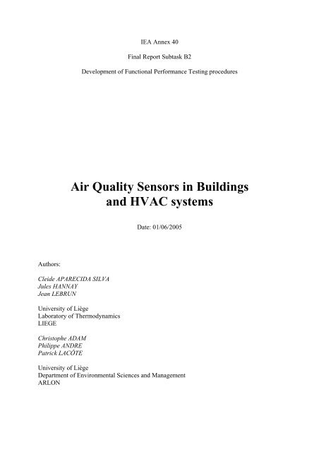
IEA Annex 40<br />
Final Report Subtask B2<br />
Development of Functional Performance Testing procedures<br />
Air Quality Sensors in Buildings<br />
and HVAC systems<br />
Date: 01/06/2005<br />
Authors:<br />
Cleide APARECIDA SILVA<br />
Jules HANNAY<br />
Jean LEBRUN<br />
University of Liège<br />
Laboratory of Thermodynamics<br />
LIEGE<br />
Christophe ADAM<br />
Philippe ANDRE<br />
Patrick LACÔTE<br />
University of Liège<br />
Department of Environmental Sciences and Management<br />
ARLON
1 Description of the considered object<br />
This specification concerns the air quality sensors installed in the building and in the HVAC<br />
systems. A more general information about sensors validation is given in generic FPT,[12], to<br />
which an automatic reference is done whenever required.<br />
1.1 Operating principles<br />
Two types of pollutants are generally measured in building and HVAC systems: the CO2 and<br />
VOC ( volatile <strong>org</strong>anic compounds) sensors.<br />
1.1.1 CO2 sensors<br />
CO2 is not a pollutant as such, provided it remains in the acceptable range. The CO2<br />
concentration is nevertheless a good indicator of the occupancy rate, as well as of the activity<br />
level in a room or in a building. CO2 sensors are usually measuring the absorption in a part of<br />
the infrared range by the measured gas. Thermal energy associated to the absorption process<br />
is proportional to the gas concentration.<br />
Figure 1 gives the rates of CO2 generation for several activities, [11].<br />
Figure 1: Rates of CO 2 generation for various activities<br />
The rate of CO2 production varies with diet and health, as well as with the duration and<br />
intensity of physical activity. The more exertion an activity entails, as measured in metabolic<br />
equivalent task (MET) units, the more carbon dioxide is produced [11].<br />
2
1.1.2 VOC sensors (multi-gas sensors)<br />
The VOC (volatile <strong>org</strong>anic compounds) sensors are based upon the absorption of in<strong>org</strong>anic<br />
ions on a porous heated surface. This modifies the electrical resistance of a semi-conductor.<br />
Those detectors are sensible to a wide range of <strong>org</strong>anic components, as well as to other<br />
molecules (Figure 2). They are also very sensible to tobacco smoke.<br />
Figure 2: Resistance variation of a VOC sensor to different gases<br />
(Air, CO, Methane, Ethanol, Propane, Hydrogen)<br />
1.2 Data provided by the manufacturers<br />
Data are generally provided as "data sheets". Typical examples of data sheets, corresponding<br />
to a C02 and to VOC sensors respectively, are given in Figures 3 and 4.<br />
3
Figure 3: Example of CO2 sensor data sheet<br />
4
Figure 4: Example of air quality sensor data sheet<br />
5
1.3 Problems to be considered<br />
1.3.1 General problems<br />
All problems listed in the reference document [12] are relevant for air quality sensors.<br />
1.3.2 Specific problems for air quality sensors<br />
Furthermore, air quality sensors have to fulfil specific installation and calibration<br />
requirements, and attention must be paid to sensors location and connection:<br />
• Sensors should be located in the return ducts, not too far from the grille;<br />
• If located in the rooms, sensors should not be too close to occupants, not too close to<br />
windows and correctly vented;<br />
• Sensors have to be continously connected.<br />
6
2 Description of the testing procedures, [12], [13]<br />
For commissioning sensors, a number of methods are available, ranging from basic "visual"<br />
inspection operations to advanced validation methods. The most advanced methods are<br />
providing "self-calibrating" characteristics to the sensors [12].<br />
2.1 Visual observation of measuring results<br />
2.1.1 Summary of the test specifications<br />
This "basic" method consists in observing the measuring results of the measurement for one<br />
or for several variables and to check if there is no major problem.<br />
Typical "obvious" problems are :<br />
- interruption of measurement<br />
- values out of range for a long time<br />
- apparent random evolution of measurement<br />
• Objectives and sequence of the test : Detection of anormalities in the sensors readings<br />
• List of operational conditions to test : Current operation of the HVAC system<br />
• Requisite : None<br />
• Required material : None<br />
• Time required for the test execution : Short : time required for observation of<br />
measurements (display on screen, printing of output file, ...)<br />
2.1.2 Preparation phase: evaluation of available data and of expected<br />
performances<br />
- Measurement points available for the test: all air quality measurement points are<br />
potentially concerned by this test procedure;<br />
- No specific measuring techniques required<br />
- Data helpful for this testing procedure :<br />
- information about problems having occured in the past<br />
- technical data about sensors : expected "noise", theoretical time constant, expected<br />
range of variation, ...<br />
- scheme of the HVAC system showing sensors location<br />
- No additional instrumentation required.<br />
2.1.3 Execution phase<br />
2.1.3.1 Summary of the test method<br />
This "basic" test method consists in using the BEMS to observe the evolution of typical<br />
sensor readings.<br />
7
2.1.3.2 Experimental method<br />
- Select typical variables to display on the BEMS;<br />
- Observe evolution of selected variables<br />
- Optionally, print selected graphs or save for future processing.<br />
2.1.3.3. Contents of the test report<br />
- Date and time<br />
- Current operation of the system<br />
- List of selected variables<br />
- For each selected variables :<br />
- typical evolution<br />
- comments<br />
- Summary of test results.<br />
2.1.4 Illustration Example<br />
CO2 tests are currently used in order to identify the airflow rate supplied to an air-conditioned<br />
zone. An example of monitoring device, including a CO2 is shown in Figure 5.<br />
Examples or recordings performed in two zones are shown in Figure 6. It appears here that<br />
the probe installed in the office B3708 has an offset which should be corrected.<br />
Figure 5: Example of monitoring device<br />
8
2400<br />
CO2 concentration [ppm]<br />
2000<br />
1600<br />
1200<br />
800<br />
400<br />
0<br />
19/03/02<br />
00:00:00<br />
19/03/02<br />
12:00:00<br />
20/03/02<br />
00:00:00<br />
20/03/02<br />
12:00:00<br />
21/03/02<br />
00:00:00<br />
21/03/02<br />
12:00:00<br />
Time<br />
CO2_B3708<br />
CO2_B3508<br />
Figure 6: Examples of evolutions of CO2 concentrations<br />
9
2.2 Diagnosis tests<br />
2.2.1 Summary of specifications<br />
This method consists in performing test cycles. In other words, the system is brought into<br />
specific operational conditions where an expected and easily predictible relation between<br />
sensors can be observed.<br />
• Objectives: detection of the qualitative response of a sensor to a given sollicitation for<br />
which the expected response is known.<br />
• Operating conditions: typical conditions which involve a predictible behaviour of the<br />
sensor response (eg “breathing” above a CO2 sensor and checking an increase of the<br />
sensor response).<br />
• Pre-requisite: the “artificial” configuration of the system should concern fault-free<br />
components<br />
• Required material: None (if using the BEMS).<br />
• Required time: Short (a few minutes for each test).<br />
2.2.2 Preparation phase: evaluation of available data and of expected<br />
performance<br />
Cfr § 2.1.2.<br />
2.2.3 Execution phase<br />
2.2.3.1 Summary of the test method<br />
The test method consists in generating (or taking profit of) some specific operating conditions<br />
and in observing the behaviour of pre-defined sensors.<br />
2.2.3.2 Experimental method<br />
Testing conditions are either generated or are naturally occuring and presenting “interesting”<br />
characteristics. In both cases, the method consists in observing (or recording) the behaviour of<br />
some selected variable.<br />
Example: moving the fresh air damper and observing the CO2 concentration at air discharge.<br />
2.2.3.3 Contents of the test report<br />
Date and time<br />
Selected (or generated) operational conditions<br />
10
For each condition:<br />
- Description of the operation imposed<br />
- Method to generate (or obtain) it<br />
- Variables to observe<br />
- Typical evolution<br />
- Comments<br />
Summary of tests results.<br />
3 References<br />
[1] SELLERS et al “HPCBS Control System Design Guide”. California Energy Commission.<br />
Public Interest Energy Research Program, 2003<br />
[2] DEXTER, A.L. ; PAKANEN, J. editors. IEA Annex 34 final report, IEA ECBCS, 2002<br />
[3] VISIER, J. Ch. Editor “IEA Annex 40 final report”, IEA ECBCS, 2005<br />
[4] XIAO, F.; WANG, S. “Sensors fault diagnosis for re-commissioning of AHU monitoring<br />
instruments”. IEA Annex 40 working document n° , 2002<br />
[5] WANG, J.-B.; WANG, S.; BURNETT, J. „FDD and soft fault estimation in<br />
commissioning BMS monitoring instruments of central chilling plant”. Proceedings System<br />
Simulation in Buildings 98, Liège, 1998<br />
[6] YOSHIDA, H.; KUMAR, S.; MORITA, Y. „Online fault detection and diagnosis in VAV<br />
air handling unit by RARX model”. Energy and Buildings, vol. 33, n°4, pp 391-410, 2001.<br />
[7] ISERMANN, R. “Supervision, fault-detection and fault-diagnosis methods: an<br />
introduction”. Control Engineering practice, vol. 5, n°5, pp 639-652, 1997<br />
[8] ASHRAE Fundamentals Chapter 14: Measurement and Instruments<br />
[9] Sontay Limited, www.sontay.com<br />
[10] http://www.madur.com<br />
[11] MURPHY J., BRADLEY B., “Using CO 2 for Demand-Controlled Ventilation”,<br />
Engineers Newsletter, Volume 31 No. 3, 2002 - www.trane.com<br />
[12] APARECIDA SILVA C., HANNAY J., LEBRUN J., ADAM C., ANDRE P., LACÔTE<br />
P., FPT S09: “Sensors of HVAC systems” , Laboratory of Thermodynamics and Department<br />
of Environmental Sciences and Management, University of Liège, Belgium<br />
[13] LIU M., CLARIDGE D.E., “ Tools and Equipment for Continuous <strong>Commissioning</strong>”,<br />
Annex 40 – subtask B2, mars 2001<br />
[14] CUEVAS C., LEBRUN J., LACÔTE P. ANDRE P., “Recommissioning of VAV<br />
boxes “,september 2002, Laboratory of Thermodynamics and Department of Environmental<br />
Sciences and Management, University of Liège, Belgium.<br />
11