Disorder-Enhanced Imaging with Spatially Controlled Light
Disorder-Enhanced Imaging with Spatially Controlled Light
Disorder-Enhanced Imaging with Spatially Controlled Light

Create successful ePaper yourself
Turn your PDF publications into a flip-book with our unique Google optimized e-Paper software.
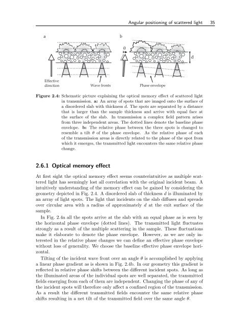
Angular positioning of scattered light 35<br />
a<br />
b<br />
θ<br />
d<br />
Effective<br />
direction<br />
Wave fronts<br />
Phase envelope<br />
Figure 2.4: Schematic picture explaining the optical memory effect of scattered light<br />
in transmission. a: An array of spots that are imaged onto the surface of<br />
a disordered slab <strong>with</strong> thickness d. The spots are separated by a distance<br />
that is larger than the sample thickness and arrive <strong>with</strong> equal face at<br />
the surface of the slab. In transmission a complex field pattern arises<br />
from three independent areas. The dotted lines denote the baseline phase<br />
envelope. b: The relative phase between the three spots is changed to<br />
resemble a tilt θ of the phase envelope. As the relative phase of each<br />
of the transmission areas is directly related to the phase of the spot from<br />
which it emerges, the transmitted light encounters the same relative phase<br />
change.<br />
2.6.1 Optical memory effect<br />
At first sight the optical memory effect seems counterintuitive as multiple scattered<br />
light has seemingly lost all correlation <strong>with</strong> the original incident beam. A<br />
intuitively understanding of the memory effect can be gained by considering the<br />
geometry depicted in Fig. 2.4. A disordered slab of thickness d is illuminated by<br />
an array of light spots. The light that incidents on the slab diffuses and spreads<br />
over circular area <strong>with</strong> a radius of approximately d at the exit surface of the<br />
sample.<br />
In Fig. 2.4a all the spots arrive at the slab <strong>with</strong> an equal phase as is seen by<br />
the horizontal phase envelope (dotted lines). The transmitted light fluctuates<br />
strongly as a result of the multiple scattering in the sample. These fluctuations<br />
make it elaborate to denote the phase envelope. However, as we are only interested<br />
in the relative phase changes we can define an effective phase envelope<br />
<strong>with</strong>out loss of generality. We choose the baseline effective phase envelope horizontal.<br />
Tilting of the incident wave front over an angle θ is accomplished by applying<br />
a linear phase gradient as is shown in Fig. 2.4b. In our geometry this gradient is<br />
reflected in relative phase shifts between the different incident spots. As long as<br />
the illuminated areas of the individual spots are well separated, the transmitted<br />
fields emerging from each of them are independent. Changing the phase of any of<br />
the incident spots will therefore only affect a confined region of the transmission.<br />
As a result the different transmitted fields encounter the same relative phase<br />
shifts resulting in a net tilt of the transmitted field over the same angle θ.