RP-IS-909S new - Backflow Supply
RP-IS-909S new - Backflow Supply
RP-IS-909S new - Backflow Supply

Create successful ePaper yourself
Turn your PDF publications into a flip-book with our unique Google optimized e-Paper software.
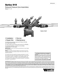
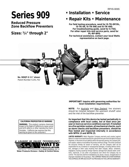
Series 909<br />
Reduced Pressure<br />
Zone <strong>Backflow</strong> Preventers<br />
Sizes: 3 /4" through 2"<br />
<strong>RP</strong>/<strong>IS</strong>-<strong>909S</strong><br />
• Installation • Service<br />
• Repair Kits • Maintenance<br />
For field testing procedure, send for <strong>IS</strong>-TK-DP/DL,<br />
<strong>IS</strong>-TK-9A, <strong>IS</strong>-TK-99E and <strong>IS</strong>-TK-99D.<br />
For troubleshooting guide, send for S-TSG.<br />
For other repair kits and service parts, send for<br />
PL-<strong>RP</strong>-BPD.<br />
For technical assistance, contact your local Watts<br />
representative on back page.<br />
No. 909QT-S 1 1 ⁄2" shown<br />
Patent Number 4,241,752<br />
IMPORTANT: Inquire with governing authorities for<br />
local installation requirements.<br />
NOTE: For Australia and New Zealand, line strainers<br />
should be installed between the upstream shutoff valve<br />
and the inlet of the backflow preventer.<br />
CALIFORNIA PROPOSITION 65 WARNING<br />
WARNING: This product contains chemicals<br />
known to the State of California to cause cancer<br />
and birth defects or other reproductive harm.<br />
(Installer: California law requires that this<br />
warning be given to the consumer.)<br />
Its important that this device be tested periodically in<br />
compliance with local codes, but at least once per<br />
year or more as service conditions warrant. If installed<br />
on a fire sprinkler system, all mechanical checks, such<br />
as alarm checks and backflow preventers, should be<br />
flow tested and inspected internally in accordance<br />
with NFPA 13 and NFPA 25.<br />
LIMITED WARRANTY: Watts Regulator Company warrants each product against<br />
defects in material and workmanship for a period of one year from the date of original<br />
shipment. In the event of such defects within the warranty period, the Company will,<br />
at its option, replace or recondition the product without charge. This shall constitute<br />
the exclusive remedy for breach of warranty, and the Company shall not be<br />
responsible for any incidental or consequential damages, including without limitation,<br />
damages or other costs resulting from labor charges, delays, vandalism,<br />
negligence, fouling caused by foreign material, damage from adverse water conditions,<br />
chemicals, or any other circumstances over which the Company has no<br />
control. This warranty shall be invalidated by any abuse, misuse, misapplication or<br />
improper installation of the product. THE COMPANY MAKES NO OTHER WARRAN-<br />
TIES EXPRESS OR IMPLIED EXCEPT AS PROVIDED IN TH<strong>IS</strong> LIMITED WARRANTY.
Basic Installation Instructions<br />
First<br />
Check<br />
909QT<br />
Relief<br />
Valve<br />
Second<br />
Check<br />
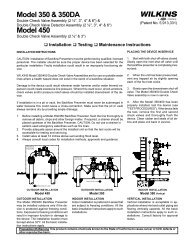
Watts 3 ⁄4" - 2" 909QT High Capacity Relief Series:<br />
Location and Installation Considerations<br />
1. <strong>Backflow</strong> preventers must be installed in high-visibility locations in order to allow for immediate notice of telltale<br />
discharge or other malfunction. This location should also facilitate testing and servicing, and protect against<br />
freezing and vandalism.<br />
2. Installing a backflow preventer in a pit or vault is not recommended as flooding of the pit will cause a crossconnection.<br />
Ensure that all local codes and required safety provisions are met. An air gap below the relief port<br />
must be maintained so as to avoid, flooding and submersion of the assembly, which may lead to a cross-connection.<br />
3. A strainer should be installed ahead of the backflow preventer to protect all internal components from unnecessary<br />
fouling.<br />
CAUTION - Do not install a strainer ahead of the backflow preventer on seldom-used, emergency water lines (i.e.<br />
fire sprinkler lines). The strainer mesh could potentially become clogged with debris present in the water and cause<br />
water blockage during an emergency.<br />
4. Normal discharge and nuisance spitting are accommodated by the use of a Watts air gap fitting and a fabricated<br />
indirect waste line. Floor drains of the same size MUST be provided in case of excessive discharge.<br />
5. When a 909 Series backflow preventer is installed for dead-end service applications (i.e. boiler feed lines, cooling<br />
tower makeup or other equipment with periodic flow requirements), discharge from the relief vent may occur due<br />
to water supply pressure fluctuation during static no-flow conditions. A check valve may be required ahead of the<br />
backflow preventer. *Please see “Troubleshooting”, page 7, prior to installation.<br />
6. The 909 Series backflow preventer is designed so that the critical level of the relief valve is positioned below the<br />
first check. This unique feature allows the valve to be installed either vertically or horizontally.<br />
7. Installation procedures must comply with all state and local codes. *Please see page 3 for specific installation<br />
procedures.<br />
8. Prior to installation, thoroughly flush all pipe lines to remove any foreign matter.<br />
9. Start up at Initial Installations and After Servicing: The downstream shutoff should be closed. Slowly open upstream<br />
shutoff and allow the backflow preventer to fill slowly. Bleed air at each test cock. When backflow preventer is filled,<br />
slowly open the downstream shutoff and fill the water supply system. This is necessary to avoid dislodging o-rings<br />
or causing damage to internal components.<br />
10. Test: The 909 Series backflow preventer must be tested by a certified tester at the time of installation in order to<br />
ascertain that the assembly is in full working order and may be relied upon to protect the safe drinking water as per<br />
applicable standards.<br />
How It Operates<br />
2<br />
Repair Parts: Use only original equipment, manufactured parts<br />
to protect the validated warranty.<br />
The unique relief valve construction<br />
incorporates two channels: one for air,<br />
one for water. When the relief valve<br />
opens, as in the accompanying air-in/<br />
water-out diagram, the right hand<br />
channel admits air to the top of the<br />
reduced pressure zone, relieving the<br />
zone vacuum. The channel on the left<br />
then drains the zone to atmosphere.<br />
Therefore, if both check valves foul,<br />
and simultaneous negative supply and<br />
positive back pressure develops, the<br />
relief valve uses the air-in/water-out<br />
principle to stop potential backflow.<br />
Reduced<br />
Pressure<br />
Zone<br />
Water Out<br />
Patent# 4,241,752<br />
Air In
Installation - Indoors<br />
Now available, WattsBox Insulated Enclosures,<br />
for more information, send for ES-WB or ES-WB-T.<br />
<br />
909QT-S<br />
Min.<br />
4 1 ⁄2"<br />
Air First<br />
Check<br />
Water<br />
Valve<br />
Out<br />
Relief Valve<br />
Flow Below First<br />
Air*<br />
Check Valve<br />
Gap<br />
Main<br />
Vertical Installation - Upward Flow<br />
Installation - Outside Building Above Ground<br />
WattsBoxFIBERGLASS Min. 12"<br />
Installation - Parallel Consult Local Codes for Approval<br />
909QT-S<br />
Air Gap<br />
ASSE approved for vertical installation<br />
3<br />
⁄4" - 2" flow up and down<br />
For indoor installations, it is important that the valve<br />
be easily accessible to facilitate testing and<br />
servicing. Series 909 may be installed either<br />
vertically or horizontally. If it is located in a line close<br />
to wall, be sure the test cocks are easily accessible.<br />
A drain line and air gap should be piped from the<br />
relief valve connection as shown, where evidence of<br />
discharge will be clearly visible and so that water<br />
damage will not occur. Therefore, never install in<br />
concealed locations.<br />
Note: Test cock must be located on the first or inlet<br />
shutoff valve.<br />
*For Air Gap information contact your technical<br />
sales representative or refer to ES-AG/EL.<br />
In an area where freezing conditions do not occur, Series<br />
909 can be installed outside of a building. The most<br />
satisfactory installation is above ground and should be<br />
installed in this manner whenever possible.<br />
In an area where freezing conditions can occur, Series 909<br />
should be installed above ground in an insulated enclosure.<br />
Series 909 may be installed in a vertical or horizontal line and<br />
in an accessible location to facilitate testing and servicing. A<br />
discharge line should be piped from the air gap at the relief<br />
valve connection making sure there is adequate drainage.<br />
Never pipe the discharge line directly into a drainage ditch,<br />
sewer or sump. Series 909 should never be installed where<br />
any part of the unit could become submerged in standing<br />
water. Consideration should be given to the installation of<br />
external support structure as applicable.<br />
It is generally recommended that backflow preventers never<br />
be placed in pits unless absolutely necessary, and then only,<br />
when approved by local codes. In such cases, a modified pit<br />
installation is preferred.<br />
▼<br />
▼<br />
▼<br />
<br />
<br />
Two or more smaller size valves can be piped in parallel<br />
(when approved) to serve a larger supply pipe main. This type<br />
of installation is employed where increased capacity is<br />
needed beyond that provided by a single valve and permits<br />
testing or servicing of an individual valve without shutting<br />
down the complete line.<br />
The number of valves used in parallel should be determined<br />
by the engineer's judgement based on the operating<br />
conditions of a specific installation.<br />
Table One - Capacity Required for System<br />
50 gpm 100 gpm 150 gpm 200 gpm 250 gpm 350 gpm<br />
Two 3 ⁄4" Two 1" Two 1 1 ⁄4" Two 1 1 ⁄2" Two 1 1 ⁄2" Two 2"<br />
Devices Devices Devices Devices Devices Devices<br />
Table shows total capacity provided with dual valve installations<br />
of various sizes.<br />
909QT-S<br />
(Drawings not to scale)<br />
3
Test Procedure for Reduced Pressure Assembly<br />
A. All needle valves must be closed on test kit.<br />
B. Open test cock No. 4 and flush test cocks Nos. 1, 2 and 3 on reduced pressure<br />
assembly then close test cock No. 4.<br />
C. Attach hoses as shown. Bleed air from kit, close No. 2 shutoff.<br />
Bleed Valve A<br />
Bleed Valve B<br />
High<br />
(red)<br />
Low<br />
(blue)<br />
Bypass<br />
(yellow)<br />
No. 2 shutoff<br />
909QT shown<br />
Test No. 1 - Check Valve No.2<br />
Purpose: To test check valve No. 2 for tightness against<br />
reverse flow.<br />
Requirements: Valve must be tight against reverse flow under all<br />
pressure differentials.<br />
Step 1 Slowly open the needle valve “A” high side (red) and “C”<br />
bypass (yellow). Keep the “B” low (blue) closed.<br />
Step 2 Open test cock No. 4.<br />
Step 3 Indicated pressure differential will decrease slightly. If<br />
pressure differential continues to decrease (until the vent<br />
opens) the No. 2 check valve is reported as “leaking”.<br />
Test No. 2 - Shutoff Valve No. 2<br />
Purpose: To test shutoff valve No. 2 for tightness.<br />
Step 1 After passing Test No. 1, continue to test No. 2 by<br />
closing test cock No. 2.<br />
Step 2 The indicated pressure differential will decrease slightly.<br />
If pressure differential continues to decrease<br />
(approaching “zero”) the No. 2 shutoff valve is reported<br />
to be “leaking”. Note: A leaking No. 2 shutoff will give a<br />
false reading in tests No. 3 and 4.<br />
Test No. 3 - To Test No. 1 Check Valve<br />
Purpose: To test check valve No. 1 for tightness.<br />
Requirements: Valve must be tight against reverse flow under<br />
all pressure differentials.<br />
Step 1 Close needle valve “A” high side (red) and open test<br />
cock No. 2<br />
Step 2 Close test cock No. 4. Disconnect bypass hose (yellow)<br />
at test cock No. 4.<br />
Step 3 Open needle valve “B” low (blue) and “C” bypass<br />
(yellow), bleeding to atmosphere, then closing needle<br />
valve “B” (blue) restores the system to a normal<br />
static condition.<br />
Step 4 Observe the pressure differential gauge. If there is a<br />
decrease in the indicated value, the No. 1 check valve is<br />
reported as “leaking”.<br />
Test No. 4 - Pressure Differential Relief Valve<br />
Purpose: To test operation of pressure differential<br />
relief valve.<br />
Requirements: The pressure differential relief valve must<br />
operate to maintain the “zone” between the two check valves<br />
at least 2 psi less than the supply pressure.<br />
Step 1 Close needle valve “C” bypass (yellow).<br />
Step 2 Open needle valve “A” high side (red).<br />
Step 3 Open needle valve “B” low (blue) very slowly until the<br />
differential gauge needle starts to drop.<br />
Step 4 Hold the valve at this position and observe the gauge<br />
reading at the moment the first discharge is noted from<br />
the relief valve. Record this as the opening differential<br />
pressure of the relief valve. Note: it is important that the<br />
differential gauge needle drops slowly.<br />
Step 5 Close test cocks Nos. 2 and 3. Remove hose from test<br />
cocks Nos. 2 and 3.<br />
Step 6 Use bypass hose (yellow) to relieve pressure from test<br />
kit by opening needle valve “A”, “B” and “C” and bleed<br />
valves “A” and “B”.<br />
Step 7 Remove all test equipment and open No. 2 shutoff valve<br />
of the device.<br />
4<br />
CAUTION: To prevent freezing, hold Test Kit vertically to drain differential gauge and hoses prior to placing in case.<br />
For additional testing information, send for <strong>IS</strong>-TK-DP/DL, <strong>IS</strong>-TK-9A, <strong>IS</strong>-TK-99E or <strong>IS</strong>-TK-99D.
Note:<br />
No special tools<br />
required to service<br />
Series 909<br />
Servicing First and Second Check Valves 3 ⁄4" to 2"<br />
Relief Valve<br />
Service Parts Kit<br />
Body<br />
1. Remove the four screws<br />
holding the first check valve cover.<br />
2. Lift off the first check valve cover. The<br />
check valve inside will come out with the<br />
cover and is attached with a bayonet type<br />
locking arrangement.<br />
3. Holding the check valve module in both hands,<br />
rotate the assembly 1/4 turn. This will disengage<br />
the disc assembly, spring and seat cover into<br />
individual components.<br />
First Check<br />
Service Parts Kit<br />
Second Check<br />
Service Parts Kit<br />
4. The disc assembly may be cleaned and reassembled, or depending upon its<br />
condition, it may be discarded and replaced with a <strong>new</strong> assembly from the<br />
service kit. O-rings should be cleaned or replaced as necessary and lightly<br />
greased with the FDA approved silicon grease which is also furnished with<br />
the service kit.<br />
5. Reassemble the check valve module in the reverse order. Service is identical<br />
for both the first and second check valves.<br />
3<br />
⁄4" - 2" Replacement Parts<br />
Cover<br />
Cover<br />
O-ring<br />
Spring<br />
Disc<br />
Assembly<br />
Seat<br />
Seat<br />
O-ring<br />
Note: The springs and covers of the first<br />
and second check valves are not<br />
interchangeable. The heavier spring<br />
loaded module should be in the first check<br />
and the lighter in the second check<br />
module.<br />
For further details contact your local technical sales representative, see back page.<br />
When ordering, specify Ordering Code Number, Kit Number † and Valve Size<br />
First Check Kits<br />
Complete Rubber Parts<br />
Order No. Kit. No. Sizes<br />
Order No. Kit No. Size<br />
0887120 RK 909 CK1 3<br />
⁄4" - 1"<br />
0887133 RK 909 CK1 1 1 ⁄4" - 2"<br />
0887122 RK 909 CK1SS* 3<br />
⁄4" - 1"<br />
0887135 RK 909 CK1SS* 1 1 ⁄4" - 2"<br />
Kit includes: Disc assembly, Spring, Seat, Seat o-ring, Cover o-ring<br />
and lubricant. *Stainless Steel Seat.<br />
Second Check Kits<br />
0887121 RK 909 CK2 3<br />
⁄4" - 1"<br />
0887134 RK 909 CK2 1 1 ⁄4" - 2"<br />
0887123 RK 909 CK2SS* 3<br />
⁄4" - 1"<br />
0887136 RK 909 CK2SS* 1 1 ⁄4" - 2"<br />
Kit includes: Disc assembly, Spring, Seat, Seat o-ring, Cover o-ring<br />
and lubricant. *Stainless Steel Seat.<br />
Rubber Parts for Both Checks<br />
0887129 RK 909 RC3 3<br />
⁄4" - 1"<br />
0887142 RK 909 RC3 1 1 ⁄4" - 2"<br />
0887310 RK 909 RC3 HW 3<br />
⁄4" - 1"<br />
0887311 RK 909 RC3 HW 1 1 ⁄4" - 2"<br />
Kit includes: Check discs, Seat o-rings, Cover o-rings and lubricant.<br />
HW model has bronze disc. † Note: 1 1 ⁄4" - 2" 909/909M1 share a<br />
common kit.<br />
First Check<br />
Second Check<br />
0887130 RK 909 RT 3<br />
⁄4" - 1"<br />
0887144 RK 909 RT 1 1 ⁄4" - 2"<br />
Kit includes: Check discs, Seat o-rings, RV diaphragm, RV o-rings,<br />
Piston o-rings, Cover o-rings and lubricant.<br />
Seat Kits for One Check<br />
0887124 RK 909 S 3<br />
⁄4" - 1"<br />
0887139 RK 909 S 1 1 ⁄4" - 2"<br />
0887125 RK 909 S-SS* 3<br />
⁄4" - 1"<br />
0887140 RK 909 S-SS* 1 1 ⁄4" - 2"<br />
Kit includes: Seat, Seat o-ring and lubricant. *Stainless Steel Seat.<br />
Cover Kits<br />
0887127 RK 909 C1 3<br />
⁄4" - 1"<br />
0887128 RK 909 C2 3<br />
⁄4" - 1"<br />
0887132 RK 909 VC 3<br />
⁄4" - 1"<br />
0887137 RK 909 C4 1 1 ⁄4" - 2"<br />
0887143 RK 909 VC 1 1 ⁄4" - 2"<br />
Kit includes: Cover, Cover o-ring and lubricant.<br />
For other repair kits and parts send for PL-<strong>RP</strong>-BPD. 5
Servicing the Relief Valve 3 ⁄4" - 2"<br />
1. Remove the four bolts that hold the relief valve cover<br />
in place.<br />
2. Remove the cover. The stainless steel adapter, with o-ring<br />
attached will be free to be removed simultaneous with the<br />
removal of the cover. Pull out the relief valve assembly.<br />
Note: the spring tension in the relief valve assembly is<br />
contained in the design of the relief valve; therefore, the<br />
relief can be removed in a one-piece spool-type assembly.<br />
3. The relief valve seat and disc may be cleaned without<br />
disassembly of the relief valve assembly. If it is determined<br />
that the relief valve diaphragm and/or disc should be<br />
replaced, the relief valve module can be readily<br />
disassembled without the use of special tools.<br />
Repair Kits †<br />
Relief Valve Kits<br />
Order Code No. Kit No. Size<br />
0887126 RK 909 VT 3<br />
⁄4" - 1"<br />
0887138 RK 909 VT 1 1 ⁄4" - 2"<br />
Kit includes: Relief valve assembly, Seat, Seat o-ring, Cover o-ring<br />
and lubricant.<br />
Rubber Parts for Relief Valve<br />
0887131 RK 909 RV 3<br />
⁄4" - 1"<br />
0887141 RK 909 RV 1 1 ⁄4" - 2"<br />
Kit includes: Diaphragm, Disc assembly, Seat o-ring, RV o-ring,<br />
Piston o-rings, Cover o-ring and lubricant.<br />
Seat Kits for Relief Valve<br />
0887372 RK 909 SV 3<br />
⁄4" - 1"<br />
0887371 RK 909 SV 1 1 ⁄4" - 2"<br />
Kit includes: Seat, Seat o-ring, Piston o-ring and lubricant.<br />
†<br />
Note: 1 1 ⁄4" - 2" 909/909M1 share a common kit.<br />
Piston<br />
Size 3 ⁄4" - 1"<br />
Piston<br />
O-ring<br />
Disc Assembly<br />
RV O-Ring<br />
To Prevent Shaft Damage Assemble As Shown:<br />
Relief Valve<br />
Assembly<br />
Seat<br />
Caution: If cover will not press against body, assembly is crooked and tightening bolts will bend shaft. Do not force the<br />
cover into place as damage may result from misalignment.<br />
Cover<br />
Diaphragm<br />
Size 1 1 ⁄4" - 2"<br />
Cover<br />
(2) Piston<br />
O-rings<br />
Stem<br />
Seat<br />
O-ring<br />
Body<br />
Relief Valve<br />
Assembly<br />
Seat<br />
O-ring<br />
Piston<br />
Stem<br />
Diaphragm<br />
(2) RV O-Rings Seat<br />
Disc Assembly<br />
For further details contact your local technical sales<br />
representative, see back page.<br />
Figure 1<br />
Figure 2<br />
Figure 3<br />
Figure 1:<br />
To assemble the Relief Valve Assembly<br />
have a screwdriver ready.<br />
6<br />
Figure 2:<br />
Depress the Relief Valve Assembly,<br />
carefully guiding it against the two<br />
pound spring load. When properly<br />
aligned, the piston is in the cylinder<br />
bore. Insert the screwdriver as shown.<br />
Figure 3:<br />
The Relief Valve Assembly is held<br />
encapsulated by the screwdriver. You<br />
should now have both hands free to<br />
bolt down the cover. Insert and snug<br />
two bolts 180° apart to hold the cover.<br />
Finish inserting the remaining bolts and<br />
snug up evenly, alternating until secure.<br />
Remove the screwdriver.
Trouble Shooting Guide - <strong>Backflow</strong> Preventers<br />
Problem Cause Solution<br />
A. Valve spits periodically from the vent.<br />
A.1 Fluctuating supply pressure.<br />
A.2 Fluctuating downstream pressure.<br />
B. Valve drips continually from the vent<br />
B.1 Fouled first check.<br />
B.2 Damaged or fouled relief valve seat.<br />
B.3 Relief valve piston o-ring not free to move<br />
due to pipe scale, dirt or build up of<br />
mineral deposits.<br />
B.4 Excessive back pressure, freezing or water<br />
hammer has distorted the second check.<br />
B.5 Electrolysis of relief valve seat or first<br />
check seats.<br />
B.6 Valve improperly reassembled.<br />
C. Valve exhibits high pressure drop.<br />
C.1 Fouled strainer.<br />
C.2 Valve too small for flows encountered.<br />
D. No water flow downstream of valve.<br />
D. Valve installed backwards.<br />
E. Valve does not test properly.<br />
E.1 Follow manufacturer's test procedure<br />
E.2 Leaky downstream gate valve.<br />
F. Valve quickly and repeatedly fouls<br />
following servicing.<br />
F. Debris in pipe line is too fine to be trapped<br />
by strainer.<br />
G. Winterization of backflow preventers.<br />
A.1 Install a soft seated check valve immediately<br />
upstream of the device. (Watts 3 ⁄4" - 2" No. 601<br />
bronze valve.)<br />
A.2 Install a soft seated check valve downstream of<br />
the device close as possible to the shutoff valve.<br />
(Watts 3 ⁄4" - 2" No. 601 bronze valve.)<br />
B.1 Flush valve. If flushing does not resolve problem,<br />
disassemble valve and clean or replace the<br />
first check.<br />
B.2 Clean or replace the relief valve seat.<br />
B.3 Clean, grease or replace the piston o-ring.<br />
B.4 Eliminate source of excessive back pressure or<br />
water hammer in the system downstream of the<br />
device. Use Watts No. 601 to dampen out back<br />
pressure and No. 15 to eliminate water hammer.<br />
Replace defective second check assembly. In<br />
case of freezing; thaw, disassemble and inspect<br />
internal components. Replace as necessary.<br />
B.5 Replace relief valve seat or inlet cover. Install<br />
dielectric unions (Watts series 3001 through 3006).<br />
Electrically ground the piping system and/or electrically<br />
isolate the device with plastic pipe immediately<br />
upstream and downstream of the device.<br />
B.6 If valve is disassembled during installation, caution<br />
must be exercised to install check springs in their<br />
proper location.<br />
C.1 Clean strainer element or replace.<br />
C.2 Install proper size device based upon<br />
flow requirements.<br />
D. Install valve in accordance with flow<br />
direction arrow.<br />
E.1, E.2<br />
Clean or replace gate valve with full port ball<br />
valves or resilient wedge shutoff valves.<br />
F. Install finer mesh strainer element in the strainer.<br />
G. Electric heat-tape wrap closely together around<br />
valve body. Build a small shelter around the valve<br />
with a large light bulb installed and left on<br />
at all times.<br />
If supply line is not used during the winter, removal<br />
of the complete body is the best. This<br />
would create an air gap to eliminate any<br />
possible backflow.<br />
7