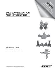
Series 919 - Backflow Supply
Series 919 - Backflow Supply
Series 919 - Backflow Supply

Create successful ePaper yourself
Turn your PDF publications into a flip-book with our unique Google optimized e-Paper software.
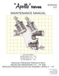
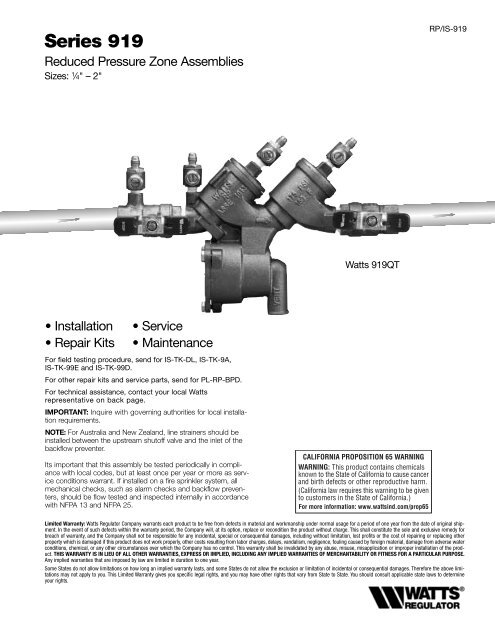
<strong>Series</strong> <strong>919</strong><br />
Reduced Pressure Zone Assemblies<br />
Sizes: 1 ⁄4" – 2"<br />
RP/IS-<strong>919</strong><br />
Watts <strong>919</strong>QT<br />
• Installation<br />
• Repair Kits<br />
• Service<br />
• Maintenance<br />
For field testing procedure, send for IS-TK-DL, IS-TK-9A,<br />
IS-TK-99E and IS-TK-99D.<br />
For other repair kits and service parts, send for PL-RP-BPD.<br />
For technical assistance, contact your local Watts<br />
representative on back page.<br />
IMPORTANT: Inquire with governing authorities for local installation<br />
requirements.<br />
NOTE: For Australia and New Zealand, line strainers should be<br />
installed between the upstream shutoff valve and the inlet of the<br />
backflow preventer.<br />
Its important that this assembly be tested periodically in compliance<br />
with local codes, but at least once per year or more as service<br />
conditions warrant. If installed on a fire sprinkler system, all<br />
mechanical checks, such as alarm checks and backflow preventers,<br />
should be flow tested and inspected internally in accordance<br />
with NFPA 13 and NFPA 25.<br />
Limited Warranty: Watts Regulator Company warrants each product to be free from defects in material and workmanship under normal usage for a period of one year from the date of original shipment.<br />
In the event of such defects within the warranty period, the Company will, at its option, replace or recondition the product without charge. This shall constitute the sole and exclusive remedy for<br />
breach of warranty, and the Company shall not be responsible for any incidental, special or consequential damages, including without limitation, lost profits or the cost of repairing or replacing other<br />
property which is damaged if this product does not work properly, other costs resulting from labor charges, delays, vandalism, negligence, fouling caused by foreign material, damage from adverse water<br />
conditions, chemical, or any other circumstances over which the Company has no control. This warranty shall be invalidated by any abuse, misuse, misapplication or improper installation of the product.<br />
THIS WARRANTY IS IN LIEU OF ALL OTHER WARRANTIES, EXPRESS OR IMPLIED, INCLUDING ANY IMPLIED WARRANTIES OF MERCHANTABILITY OR FITNESS FOR A PARTICULAR PURPOSE.<br />
Any implied warranties that are imposed by law are limited in duration to one year.<br />
Some States do not allow limitations on how long an implied warranty lasts, and some States do not allow the exclusion or limitation of incidental or consequential damages. Therefore the above limitations<br />
may not apply to you. This Limited Warranty gives you specific legal rights, and you may have other rights that vary from State to State. You should consult applicable state laws to determine<br />
your rights.
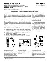
Basic Installation Instructions 1 ⁄4" – 2"<br />
<strong>Series</strong> <strong>919</strong> Reduced Pressure Zone Assemblies<br />
Indoor Installation<br />
For indoor installations, make sure the series <strong>919</strong> is easily<br />
accessible to facilitate testing and servicing. Do not install in<br />
concealed locations. If the location of the series <strong>919</strong> is parallel<br />
and close to the wall, make sure the test cocks are easily<br />
accessible, and the drain line can adequately drain if required.<br />
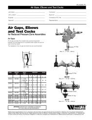
An air gap and drain line (see literature ES-AG/EL/TC) are piped<br />
from the relief valve connection as shown, allowing evidence of<br />
discharge to be clearly visible and preventing the occurrence of<br />
water damage.<br />
Indoor Installation<br />
Meter<br />
Strainer<br />
12" Minimum<br />
(refer to local codes)<br />
Watts<br />
1<br />
⁄4" – 2" <strong>919</strong><br />
Air Gap<br />
Outdoor, Above Ground Installation<br />
For outdoor installations, it is recommended that you install the<br />
series <strong>919</strong>AQT where there are no freezing conditions and<br />
above ground whenever possible.<br />
You must install the series <strong>919</strong> in an accessible location to<br />
facilitate testing and servicing. The installation must also allow<br />
for adequate drainage from the air gap and the discharge line<br />
if needed.<br />
WARNING<br />
1. Do not allow the drain line to empty directly into a drainage<br />
ditch, sewer system, or sump.<br />
2. Do not install the series <strong>919</strong> in any location where any part<br />
of the unit could become submerged in standing water.<br />
Outdoor Installation<br />
FIBERGLASS WattsBox<br />
Min. 12"<br />
Watts<br />
1<br />
⁄4" – 2" <strong>919</strong>AQT<br />
Now available, WattsBox Insulated Enclosures,<br />
for more information, send for literature ES-WB.<br />
Parallel Installation<br />
For parallel installations, you can install two or more small sized<br />
series <strong>919</strong>'s (when approved) to serve a large supply pipe main.<br />
You can use this type of installation in an application where<br />
increased capacity beyond that provided by a single valve is<br />
required. Additionally, this type of installation permits testing<br />
and/or servicing of a single valve without shutting down the<br />
complete line.<br />
The number of series <strong>919</strong> units installed in parallel should be<br />
determined by the engineer's judgement, based on the operating<br />
conditions of a specific application.<br />
NOTE: The total capacity of all the units installed in the application<br />
should equal or exceed that required by the system.<br />
Parallel Installation<br />
Watts<br />
1<br />
⁄4" – 2" <strong>919</strong><br />
Annual inspection of all water system safety and control valves<br />
is required and necessary. Regular inspection, testing and<br />
cleaning assures maximum life and proper product function.<br />
2
Basic Installation Instructions 1 ⁄4" – 2"<br />
A. Shutoff Valves: If you remove the shutoff valves from the series <strong>919</strong>, reassemble the shutoff<br />
valve with the test cock mounted on the inlet side of the unit.<br />
B. Always install the series <strong>919</strong> in an accessible location to facilitate testing and servicing (See<br />
page 2). *Check the state and local codes to insure that you install the backflow preventer in compliance<br />
with those codes, such as the proper height above the ground.<br />
C. It is recommended that you install a strainer ahead of the <strong>919</strong> series assemblies to protect<br />
the internal components from unnecessary fouling.<br />
CAUTION<br />
Do not install a series <strong>919</strong> with a strainer in rarely used water lines, such as a fire sprinkler system<br />
which is only used during emergencies.<br />
Start Up: Close the downstream shut-off. Open the upstream slowly and fill the valve. When<br />
the valve is filled, open the downstream shut-off slowly, and fill the water supply system. This is<br />
necessary to avoid water hammer and/or shock damage.<br />
D. Vent the air gap and drain line from the relief valve in accordance with code requirements.<br />
Terminate discharge approximately 12" above the ground or through an air gap piped to a<br />
floor drain.<br />
Air<br />
Gap<br />
Watts 1 ⁄4" – 2" <strong>919</strong><br />
*Vertical Flow Down<br />
Strainer<br />
909EL-H<br />
Elbow<br />
WARNING<br />
Do not allow the drain line to empty directly into a drainage ditch, sewer system,<br />
or sump.<br />
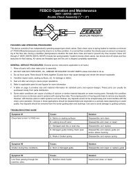
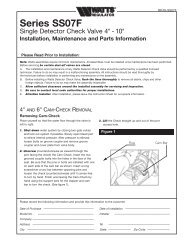
NOTE: Relief Valve Discharge Rates<br />
The series <strong>919</strong> air gap and drain line terminating above a floor drain can accommodate<br />
any moderate discharge or nuisance spitting through the relief valve.<br />
However, to prevent water damage in the case of a catastrophic failure, you may<br />
need to design the floor drain size to accommodate the increased discharge.<br />
Refer to Figure 1 for maximum relief valve discharge rates, size, and capacity of<br />
typical floor drains.<br />
NOTE: DO NOT reduce the size of the drain line from the air gap fitting. The drain<br />
line must remain at full line size.<br />
E. After initial installation of the series <strong>919</strong>, a discharge from the relief valve may<br />
occur due to dirt and pipe compounds. This may be due to inadequate initial<br />
flushing of the pipe lines. If flushing the valve does not clear the unit, remove<br />
the first check valve and clean thoroughly, using the procedures in "Servicing<br />
First & Second Check Valves" on page 5.<br />
NOTE: Periodic relief valve discharge may occur on dead end service applications,<br />
such as boiler feed lines or cooling tower makeup lines. This may be due to fluctuating<br />
supply pressure during a static or no flow condition. To avoid this discharge,<br />
install a spring-loaded, rubber seated check valve ahead of the backflow<br />
assembly.<br />
F.It is recommended that you not place the series <strong>919</strong> in a pit or at a depth below<br />
the ground level, unless absolutely necessary. If an installation requires below<br />
ground level installation, a modified pit installation is recommended, as well as<br />
the approval of local codes. In such cases, provision should be made to always<br />
vent the drain line above the flood level. In the case of a pit drain, ensure an<br />
adequate air gap exists between the bottom of the drain line and the bottom of<br />
the pit.<br />
G. It is recommended that periodic inspection of the series <strong>919</strong> be done to<br />
check for any discharge from the relief valve. This discharge is a visual indication<br />
that the valve needs cleaning or repair. In addition, it is recommeded that<br />
periodic testing of the valve be done in compliance with local codes to ensure<br />
its proper operation.<br />
The relief vent discharges water during no-flow periods when:<br />
(1) the first check valve is fouled; or<br />
(2) the inlet pressure to the check valve drops sufficiently due to upstream pressure<br />
fluctuations. This then affects the required operating differential between<br />
the inlet pressure and the reduced pressure zone; or<br />
(3) the second check is fouled during emergency backflow or resulting from a<br />
water hammer condition.<br />
For troubleshooting guide send for literature S-TSG.<br />
NOTE: When installing the series <strong>919</strong> on fire prevention systems, special considerations<br />
are required.<br />
Fire Protection System Installations: The National Fire Protection Agency (NFPA)<br />
Guidelines require a confirming flow test be conducted by a certified tester whenever<br />
a “main line” valve is installed, such as a shut-off valve or a backflow preventer.<br />
Flow Rate gpm<br />
Flow Rate gpm<br />
1<br />
⁄4" – 1" <strong>919</strong><br />
45<br />
40<br />
35<br />
30<br />
25<br />
20<br />
15<br />
10<br />
5<br />
0<br />
0 10 20 30 40 50 60 70 80 90 100 150<br />
350<br />
300<br />
250<br />
200<br />
150<br />
100<br />
50<br />
Zone Pressure psi<br />
1 1 ⁄4" – 2" <strong>919</strong><br />
0<br />
0 10 20 30 40 50 60 70 80 90 100 150<br />
Zone Pressure psi<br />
Floor Drain<br />
1 ⁄4"– 1 ⁄2" 3 ⁄4" X 1"<br />
0 1 1 ⁄4"–1 1 ⁄2" 2"<br />
Typical Flow Rates as sized by floor drain manufacturers:<br />
2" 55 GPM 5" 350 GPM<br />
3" 112 GPM 6" 450 GPM<br />
4" 170 GPM 8" 760 GPM<br />
3
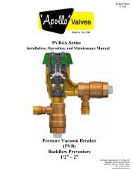
Servicing the Relief Valve 1 ⁄4" – 2"<br />
NOTES: 1. No special tools are required to service the series <strong>919</strong> 1 ⁄4" - 2".<br />
2. Before servicing, make sure the water is turned off or shut-off valves are closed.<br />
The following procedures provide information for replacing the diaphragm, the relief valve disc, and<br />
the relief valve seat. It is recommended that you visually inspect these parts to determine if a<br />
replacement or a cleaning is required.<br />
Disassembling the Relief Valve<br />
1. Remove the relief valve cover bolts while holding the cover down.<br />
2. Turn the cover counterclockwise for 1 ⁄4 turn, and lift it straight off<br />
while still applying pressure to the cover with your hand.<br />
WARNING<br />
Make sure you apply pressure to the cover as you lift it straight off. Due to the release<br />
of pressure when removing the cover, the relief valve spring may eject quickly.<br />
3. Remove the relief valve assembly (includes cover O-ring, stem and diaphragm assembly).<br />
4. Remove the relief valve spring.<br />
5. Remove the pressed in relief valve seat and seat O-ring.<br />
Replacing the Diaphragm<br />
6. Using a wrench, loosen the diaphragm assembly by turning<br />
the hex bolt counterclockwise.<br />
7. Remove the diaphragm and replace with a new diaphragm<br />
if required, or clean the existing diaphragm.The molded step<br />
of the diaphragm should point down towards the relief valve stem.<br />
8. Using a wrench, reassemble the diaphragm assembly<br />
by turning the hex bolt clockwise to tighten.<br />
Replacing the Relief Valve Disc and Seat<br />
9. Using a phillips screwdriver, remove the screw in the relief valve<br />
disc and replace the disc if required, or clean the existing disc.<br />
10.Place the screw back into the relief valve disc and tighten.<br />
11.Replace the relief valve seat with a new seat if required, or<br />
clean the existing seat.<br />
Reassembling the Relief Valve<br />
12.Place the relief valve seat back into the chamber bore.<br />
13.Slide the diaphragm assembly into the relief valve seat.<br />
14.Place the spring on to the diaphragm assembly.<br />
15.Place the cover O-ring on the diaphragm assembly.<br />
16.Line up the grooves on the relief valve cover with the grooves in the<br />
relief valve body, and turn the cover clockwise 1 ⁄4 turn to seat the cover.<br />
17.Using a wrench, place the bolts back into the cover and tighten.<br />
CAUTION<br />
If the cover does not lie flat against the relief valve body, the diaphragm assembly is not installed<br />
properly and damage can result. Remove the bolts and cover, realign the diaphragm assembly,<br />
and place the cover back on the relief valve body.<br />
18.Open the shutoff valves.<br />
4<br />
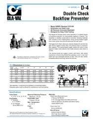
Replacement Parts 1 ⁄4" – 2"<br />
When ordering, specify Ordering Code Number, Kit number and Valve Size.<br />
ORDERING CODE KIT NO. SIZE<br />
Total Relief Valve Kits:<br />
0888130 RK <strong>919</strong> VT 1<br />
⁄4" – 1 ⁄2"<br />
0888131 RK <strong>919</strong> VT 3<br />
⁄4" – 1"<br />
0888132 RK <strong>919</strong> VT 1 1 ⁄4" – 2"<br />
Kit consists of: Relief Valve Assembly, RV Spring, and RV Cover O-ring.<br />
Relief Valve Rubber Parts Kits:<br />
0888135 RK <strong>919</strong> RV 1<br />
⁄4" – 1 ⁄2"<br />
0888136 RK <strong>919</strong> RV 3<br />
⁄4" – 1"<br />
0888137 RK <strong>919</strong> RV 1 1 ⁄4" – 2"<br />
Kit consists of: Relief Valve Disc, RV Diaphragm, RV Seat O-ring and Cover O-<br />
ring<br />
Relief Valve Seat<br />
Relief Valve<br />
Spring<br />
Cover<br />
Bolts<br />
Relief<br />
Valve<br />
Cover<br />
Relief Seat O-ring<br />
Body<br />
Relief Valve<br />
Disc Screw<br />
Relief Valve Disc<br />
Relief Valve Stem<br />
Relief Valve Diaphragm<br />
Diaphragm Nut<br />
Relief Valve Cover O-ring<br />
Quad-Ring<br />
ORDERING CODE KIT NO. SIZE<br />
Relief Valve Seat Kits:<br />
0888150 RK <strong>919</strong> SV 1<br />
⁄4" – 1 ⁄2"<br />
0888151 RK <strong>919</strong> SV 3<br />
⁄4" – 1"<br />
0888152 RK <strong>919</strong> SV 1 1 ⁄4" – 2"<br />
Kit consists of: Relief Valve Seat, RV Seat O-ring and RV Cover O-ring<br />
Relief Valve Cover Kits:<br />
888155 RK <strong>919</strong> VC 1<br />
⁄4" – 1 ⁄2"<br />
888156 RK <strong>919</strong> VC 3<br />
⁄4" – 1"<br />
888157 RK <strong>919</strong> VC 1 1 ⁄4" – 2"<br />
Kit consists of: Relief Valve Cover and Cover O-ring<br />
Air Gaps<br />
0881575 <strong>919</strong> AGA 1<br />
⁄4" – 1 ⁄2"<br />
0881576 <strong>919</strong> AGC 3<br />
⁄4" - 1"<br />
0881577 <strong>919</strong> AGF 1 1 ⁄4"- 2"
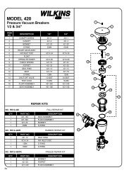
Servicing First & Second Check Valves 1 ⁄4" – 2"<br />
NOTES: 1. No special tools are required to service the <strong>Series</strong> <strong>919</strong> 1 ⁄4" - 2".<br />
2. Before servicing, make sure the water is turned off or<br />
shut-off valves are closed.<br />
1. Close shut-off valves up and downstream of the valve.<br />
2. Using an appropriate sized wrench, loosen the check valve<br />
cover. Unscrew the check valve cover and lift it off.<br />
3. Remove the spring.<br />
4. Lift out the disc holder assembly from the body of the valve.<br />
5. To reverse the seat disc, unscrew the disc screw and disassemble<br />
the disc washer and disc rubber from the disc holder assembly.<br />
Reverse the disc rubber so the opposite face is showing.<br />
6. Assemble the disc screw through the disc washer and<br />
disc rubber, and screw it into the disc holder.<br />
7. To replace the seat module, pull the seat module<br />
out of the body by gripping at the reinforcement<br />
ring. Replace the seat module with the new seat<br />
by placing it into the body seat bore.<br />
NOTE: When you tighten the cover in step 12, the<br />
cover will engage the seat module properly.<br />
8. Insert the disc holder assembly back into the seat module.<br />
9. Replace the spring ensuring that it seats properly on the<br />
disc holder.<br />
WARNING<br />
The first check valve has a heavy weight spring. The second check<br />
valve has a lighter weight spring. When reassembling the check<br />
valves, make sure you install the correct spring into the correct<br />
check valve.<br />
10.Place the cover onto the spring with the internal guide on the<br />
cover positioned inside the end coil.<br />
11.Screw the cover onto the valve body.<br />
12.Tighten the cover using the appropriate sized wrench.<br />
13.Service the second check valve using steps 2 through 12.<br />
14.Slowly open shut off valves.<br />
Check Disc Washer<br />
Check Disc Screw<br />
Reinforcement Ring<br />
Check Seat<br />
Check Seat O-<br />
ring<br />
Check Disc Holder<br />
Check Disc Rubber<br />
Check Assembly<br />
Cover<br />
Cover O-ring<br />
Check Spring<br />
Replacement Parts 1 ⁄4" – 2"<br />
When ordering, specify Ordering Code Number, Kit Number and Valve Size.<br />
ORDER CODE KIT NO. SIZE<br />
1st Check Kits:<br />
0888110 RK <strong>919</strong> CK1 1<br />
⁄4" – 1 ⁄2"<br />
0888111 RK <strong>919</strong> CK1 3<br />
⁄4"<br />
0888112 RK <strong>919</strong> CK1 1"<br />
0888113 RK <strong>919</strong> CK1 1 1 ⁄4" – 1 1 ⁄2"<br />
0888114 RK <strong>919</strong> CK1 2"<br />
Kit consists of: Check Assembly, Spring and Cover O-ring<br />
2nd Check Kits:<br />
0888115 RK <strong>919</strong> CK2 1<br />
⁄4" – 1 ⁄2"<br />
0888116 RK <strong>919</strong> CK2 3<br />
⁄4"<br />
0888117 RK <strong>919</strong> CK2 1"<br />
0888118 RK <strong>919</strong> CK2 1 1 ⁄4"-1 1 ⁄2"<br />
0888119 RK <strong>919</strong> CK2 2"<br />
Kit consists of: Check Assembly, Spring and Cover O-ring<br />
1st or 2nd Check Rubber Parts Kits:<br />
0888120 RK <strong>919</strong> RC4 1<br />
⁄4" – 1 ⁄2"<br />
0888121 RK <strong>919</strong> RC4 3<br />
⁄4"<br />
0888122 RK <strong>919</strong> RC4 1"<br />
0888123 RK <strong>919</strong> RC4 1 1 ⁄4"-1 1 ⁄2"<br />
0888124 RK <strong>919</strong> RC4 2"<br />
Kit consists of: Disc, Seat O-ring and Cover O-ring<br />
ORDER CODE KIT NO. SIZE<br />
Check Seat Kits:<br />
0888125 RK <strong>919</strong> S 1<br />
⁄4" – 1 ⁄2"<br />
0888126 RK <strong>919</strong> S 3<br />
⁄4"<br />
0888127 RK <strong>919</strong> S 1"<br />
0888128 RK <strong>919</strong> S 1 1 ⁄4"-1 1 ⁄2"<br />
0888129 RK <strong>919</strong> S 2"<br />
Kit consists of: Seat, Seat O-ring and Cover O-ring<br />
Complete Valve Rubber Parts Kits:<br />
0888140 RK <strong>919</strong> RT 1<br />
⁄4" – 1 ⁄2"<br />
0888141 RK <strong>919</strong> RT 3<br />
⁄4"<br />
0888142 RK <strong>919</strong> RT 1"<br />
0888143 RK <strong>919</strong> RT 1 1 ⁄4"-1 1 ⁄2"<br />
0888144 RK <strong>919</strong> RT 2"<br />
Kit consists of: 2 Check Discs, 2 Check Seat O-rings, 1 RV Disc<br />
Check Cover Kits:<br />
0888145 RK <strong>919</strong> C 1<br />
⁄4" – 1 ⁄2"<br />
0888146 RK <strong>919</strong> C 3<br />
⁄4"<br />
0888147 RK <strong>919</strong> C 1"<br />
0888148 RK <strong>919</strong> C 1 1 ⁄4"-1 1 ⁄2"<br />
0888149 RK <strong>919</strong> C 2"<br />
Kit consists of: Cover and Cover O-ring<br />
5
Test Procedures<br />
Reduced Pressure Zone Assemblies must be inspected and<br />
tested periodically, in accordance with local codes, to ensure<br />
proper operation of check valves within the unit.<br />
A differential pressure gauge is recommended for Test No. 1<br />
rather than a manometer for the following reasons: It utilizes<br />
minimum time to perform the test. It eliminates the necessity of<br />
closing the inlet ball valve which could release pipe scale and<br />
foreign matter into the backflow preventer. Only a slight amount<br />
of water is ‘spilled’ in test. A mercury manometer could cause a<br />
pollution hazard.<br />
Test Set Up<br />
Reduced Pressure Zone Assembly<br />
Close Valves A, B and C on Test Kit.<br />
Connect high side hose to test cock #2<br />
Connect low side hose to test cock #3. Close shutoff #2.<br />
Open test cocks #2 and #3.<br />
Open vent valve C.<br />
Open ‘high’ valve A and bleed to atmosphere until all the<br />
air is expelled.<br />
Close valve A. Open ‘low’ valve B and bleed to atmosphere until<br />
all air is expelled. Close ‘low’ valve B. Close ‘vent’ valve C.<br />
Connect vent hose to test cock #4.<br />
Test Procedure<br />
Reduced Pressure Zone Assembly<br />
Field Test Equipment Required<br />
Watts Test Kit<br />
Test No. 1<br />
Purpose: To test Check Valve No. 2 for tightness against reverse<br />
flow.<br />
Requirements: Valve must be tight against reverse flow under all<br />
pressure differentials. Slowly open the ‘high’ valve A and the<br />
‘vent’ valve C, and keep the ‘low’ valve B closed. Open test<br />
cock #4. Indicated pressure differential will decrease slightly. If<br />
pressure differential continues to decrease (until the vent opens)<br />
check valve #2 is reported as ‘leaking’.<br />
Strainer<br />
Test Cock<br />
No. 1<br />
Auxillary<br />
Test Cock<br />
High Hose<br />
(Color - Yellow)<br />
Test Cock<br />
No. 2<br />
Relief<br />
Valve<br />
Ball Type<br />
(A) Test Valves (C)<br />
(B)<br />
Needle<br />
Valve<br />
High Hose<br />
(Color - White or Red)<br />
Test Cock<br />
No. 3<br />
High Hose<br />
(Color - Blue)<br />
Test Cock<br />
No. 4<br />
Shutoff<br />
No. 2<br />
<strong>919</strong>QTS<br />
Test No. 2<br />
Purpose: To test shutoff #2 for tightness.<br />
Requirements: After passing Test No. 1, continue to Test No. 2<br />
by closing test cock #2. The indicated pressure differential will<br />
decrease slightly. If pressure differential continues to decrease<br />
(approaching “zero”), shutoff #2 is reported to be “leaking”.<br />
Test No. 3<br />
Purpose: To test Check Valve No. 1 for tightness.<br />
Requirements: Valve must be tight against reverse flow under all<br />
pressure differentials. Close ‘high’ valve A and open test cock<br />
#2. Close test cock #4. Disconnect vent hose at test cock #4.<br />
Open valves B and C, bleeding to atmosphere. Then closing<br />
valve B restores the system to a normal static condition.<br />
Observe the pressure differential gauge. If there is a decrease in<br />
the indicated value, Check Valve No. 1 is reported as “leaking”.<br />
Test No. 4<br />
Purpose: To test operation of pressure differential relief valve.<br />
Requirements: The pressure differential relief valve must operate<br />
to maintain the “zone” between the two check valves at least 2<br />
psi less than the supply pressure. Close ‘vent’ valve C. Open<br />
‘high’ valve A. Open the ‘low’ valve B very slowly until the differential<br />
gauge needle starts to drop. Hold the valve at this position<br />
and observe the gauge reading at the moment the first discharge<br />
is noted from the relief valve. Record this as the opening<br />
differential pressure of the relief valve.<br />
Note: It is important that the differential gauge needle drops<br />
slowly.<br />
Close test cocks #2 and #3. Use ‘vent’ hose to relieve pressure<br />
from test kit by opening valves A, B and C. Remove all test<br />
equipment and open shutoff #2.<br />
6
NOTES<br />
7
For Technical Assistance Call Your Authorized Watts Agent.<br />
Telephone #<br />
Fax #<br />
HEADQUARTERS: Watts Regulator Company 815 Chestnut St., North Andover, MA 01845-6098 U.S.A. 978 688-1811 978 794-1848<br />
North<br />
East<br />
Edwards, Platt & Deely, Inc. 271 Royal Ave., Hawthorne, NJ 07506 973 427-2898 973 427-4246<br />
Edwards, Platt & Deely, Inc. 368 Wyandanch Ave., North Babylon, NY 11703 631 253-0600 631 253-0303<br />
W. P. Haney Co., Inc. 51 Norfolk Ave., South Easton, MA 02375 508 238-2030 508 238-8353<br />
Mid<br />
Atlantic<br />
J. B. O’Connor Company, Inc. P.O. Box 12927, Pittsburgh, PA 15241 724 745-5300 724 745-7420<br />
RMI Glenfield Bus. Ctr., 2535 Mechanicsville Tpk., Richmond, VA 23223 804 643-7355 804 643-7380<br />
The Joyce Agency, Inc. 8442 Alban Rd., Springfield, VA 22150 703 866-3111 703 866-2332<br />
Vernon Bitzer Associates, Inc. 980 Thomas Drive, Warminster, PA 18974 215 443-7500 215 443-7573<br />
WMS Sales, Inc. (Main office) 9580 County Rd., Clarence Center, NY 14032 716 741-9575 716 741-4810<br />
South<br />
East<br />
Billingsley & Associates, Inc. 2728 Crestview Ave., Kenner, LA 70062-4829 504 602-8100 504 602-8106<br />
Billingsley & Associates, Inc. 478 Cheyenne Lane, Madison, MS 39110 601 856-7565 601 856-8390<br />
Francisco J. Ortiz & Co., Inc. Charlyn Industrial Pk., Road 190 KM1.9 - Lot #8, Carolina, Puerto Rico 00983 787 769-0085 787 750-5120<br />
Mid-America Marketing, Inc. 2776 B.M. Montgomery St., Birmingham, AL 35209 205 879-3469 205 870-5027<br />
Mid-America Marketing, Inc. 1364 Foster Avenue, Nashville, TN 37210 615 259-9944 615 259-5111<br />
Mid-America Marketing, Inc. 5466 Old Hwy. 78, Memphis, TN 38118 901 795-0045 901 795-0394<br />
Smith & Stevenson Co., Inc. 4935 Chastain Ave., Charlotte, NC 28217 704 525-3388 704 525-6749<br />
Spotswood Associates, Inc. 6235 Atlantic Blvd., Norcross, GA 30071 770 447-1227 770 263-6899<br />
Target Marketing Enterprises, Inc. 118 West Grant St., Building M, Orlando, FL 32806 407 245-7838 407 245-7833<br />
North<br />
Central<br />
Aspinall Associates, Inc. 6840 Hillsdale Court, Indianapolis, IN 46250 317 849-5757 317 845-7967<br />
Dave Watson Associates 1325 West Beecher, Adrian, MI 49221 517 263-8988 517 263-2328<br />
Disney-McLane-Woodcock, Inc. 428 McGregor Ave., Cincinnati, OH 45206 800 542-1682 877 476-1682<br />
Disney-McLane-Woodcock, Inc. 17610 S. Waterloo Rd., Cleveland, OH 44119 216 486-1010 216 486-2860<br />
Mid-Continent Marketing Services Ltd. 1724 Armitage Ct., Addison, IL 60101 630 953-1211 630 953-1067<br />
Soderholm & Associates, Inc. 7150 143rd Ave. N.W., Anoka, MN 55303 763 427-9635 763 427-5665<br />
Stickler & Associates 333 North 121 St., Milwaukee, WI 53226 414 771-0400 414 771-3607<br />
South<br />
Central<br />
Hugh M. Cunningham, Inc. 13755 Benchmark, Dallas, TX 75234 972 888-3808 972 888-3838<br />
Mack McClain & Associates 11132 South Towne Square, Suite 202, St. Louis, MO 63123 314 894-8188 314 894-8388<br />
Mack McClain & Associates, Inc. 1450 NE 69th Place, Ste. 56 Ankeny, IA 50021 515 288-0184 515 288-5049<br />
Mack McClain & Associates, Inc. 15090 West 116th St., Olathe, KS 66062 913 339-6677 913 339-9518<br />
Pro-Spec, Inc. P.O. Box 472226, Tulsa, OK 74147-2226 918 461-0066 918 461-0105<br />
Phoenix Marketing, Ltd. 2416 Candelaria N.E., Albuquerque, NM 87107 505 883-7100 505 883-7101<br />
Western<br />
Delco Sales, Inc. 1930 Raymer Ave., Fullerton, CA 92833 714 888-2444 714 888-2448<br />
Delco Sales, Inc. 111 Sand Island Access Rd., Unit I-10, Honolulu, HI 96819 808 842-7900 808 842-9625<br />
Fanning & Associates, Inc. 6765 Franklin St., Denver, CO 80229-7111 303 289-4191 303 286-9069<br />
Hollabaugh Brothers & Associates 6915 South 194th St., Kent, WA 98032 253 867-5040 253 867-5055<br />
Hollabaugh Brothers & Associates 3028 S.E. 17th Ave., Portland, OR 97202 503 238-0313 503 235-2824<br />
P I R Sales, Inc. 3050 North San Marcos Place, Chandler, AZ 85225 480 892-6000 480 892-6096<br />
Preferred Sales 31177 Wiegman Road, Hayward, CA 94544 510 487-9755 510 476-1595<br />
R. E. Fitzpatrick Sales, Inc. 4109 West Nike Dr. (8250 South), West Jordan, UT 84088 801 282-0700 801 282-0600<br />
Canada<br />
Watts Industries (Canada) Inc.<br />
(Watts Regulator Co. Division) 5435 North Service Road, Burlington, Ontario L7L 5H7 905 332-4090 905 332-7068<br />
Con-Cur West Marketing, Inc. #109-42 Fawcett Rd., Coquitlam, British Columbia V3K 6X9 604 540-5088 604 540-5084<br />
D.C. Sales, Ltd. 10-6130 4th St. S.E., Calgary, Alberta T2H 2A6 403 253-6808 403 259-8331<br />
D.C. Sales, Ltd. 11420 142 Street, Edmonton, Alberta T5M 1V1 780 496-9495 780 496-9621<br />
GTA Sales Team. Greater Toronto Area 888 208-8927 888 479-2887<br />
Hydro-Mechanical Sales, Ltd. 3700 Joseph Howe Dr., Ste. 1 Halifax, Nova Scotia B3L 4H7 902 443-2274 902 443-2275<br />
Hydro-Mechanical Sales, Ltd. 297 Collishaw St., Ste. 7 (shipping) Moncton, New Brunswick E1C 9R2 506 859-1107 506 859-2424<br />
Hydro-Mechanical Sales, Ltd. 85 Tolt Rd., St. Phillips, Newfoundland A1B 3M7 709 895-0090 709 895-0091<br />
Le Groupe B.G.T., Inc. 2800 Rue Dalton Ste. 3, Ste-Foy, Quebec G1P 3S4 418 657-2800 418 657-2700<br />
Le Groupe B.G.T., Inc. 86 des Enterprises #208, Boisbriand, Quebec J7G 2T3 450 434-9010 450 434-9848<br />
Mar-Win Agencies, Ltd. 1123 Empress St., Winnipeg, Manitoba R3E 3H1 204 775-8194 204 786-8016<br />
Northern Mechanical Sales P.O. Box 280 (mailing) 163 Pine St. (shipping), Garson, Ontario P3L 1S6 705 693-2715 705 693-4394<br />
Palser Enterprises, Ltd. 1885 Blue Heron Dr., #4, London, Ontario N6H 5L9 519 471-9382 519 471-1049<br />
RAM Mechanical Marketing 441 Quebec St., Regina, Saskatchewan S4R 1K8 306 525-1986 306 525-0809<br />
RAM Mechanical Marketing #13 – 1100 7th Avenue North, Saskatoon, Saskatchewan S7K 2V9 306 244-6622 306 244-0807<br />
Walmar Mechanical Sales 24 Gurdwara Rd., Nepean, Ontario K2E 8B5 613 225-9774 613 225-0673<br />
0328<br />
EXPORT Hdqtrs.: Watts Regulator Co. 815 Chestnut St., North Andover, MA 01845-6098 U.S.A. 978 688-1811 978 794-1848<br />
Watts USA website: www.wattsreg.com<br />
Watts Canada website: www.wattscanada.ca<br />
RP/IS-<strong>919</strong> 0338 EDP# 1915346 © Watts Regulator Company, 2003 Printed in U.S.A.