Model 40-200 Series - Backflow Supply
Model 40-200 Series - Backflow Supply
Model 40-200 Series - Backflow Supply

Create successful ePaper yourself
Turn your PDF publications into a flip-book with our unique Google optimized e-Paper software.
BFMM<strong>40</strong>00<br />
6-07<br />
MAINTENANCE MANUAL<br />
Covering <strong>Model</strong>s:<br />
<strong>40</strong>-<strong>200</strong> <strong>Series</strong> (1/4” - 10”)<br />
<strong>40</strong>-<strong>200</strong>S <strong>Series</strong> (1/4” - 1”)<br />
<strong>40</strong>-700 <strong>Series</strong> (3” - 10”)<br />
REDUCED PRESSURE PRINCIPLE (RPZ)<br />
BACKFLOW PREVENTERS 1/4" - 10" AND<br />
REDUCED PRESSURE DETECTOR ASSEMBLY (RPDA) 3" - 10"<br />
Conbraco Industries, Inc.<br />
P.O. Box 247<br />
Matthews, NC 28106<br />
Phone: (704) 841-6000<br />
Fax 704-841-6020<br />
www.conbraco.com
TABLE OF CONTENTS<br />
Reduced Pressure Principle <strong>Backflow</strong> Preventer 1/4" - 10" &<br />
Reduced Pressure Detector Assembly 3" - 10"<br />
Section<br />
Page<br />
I Description and Operation . . . . . . . . . . . . . . . . . . . . . . . . . . . . . . . . . . . . . . . . . . . . .2<br />
II Installation . . . . . . . . . . . . . . . . . . . . . . . . . . . . . . . . . . . . . . . . . . . . . . . . . . . . . . . . .3<br />
III Trouble Shooting Guide . . . . . . . . . . . . . . . . . . . . . . . . . . . . . . . . . . . . . . . . . . . . . . .4<br />
IV Maintenance Instructions 1/4" - 2" . . . . . . . . . . . . . . . . . . . . . . . . . . . . . . . . . . . . . .5<br />
V Maintenance Instructions 2-1/2" - 10" . . . . . . . . . . . . . . . . . . . . . . . . . . . . . . . . . . .6<br />
VI Testing Procedure 1/4" - 10" . . . . . . . . . . . . . . . . . . . . . . . . . . . . . . . . . . . . . . .7 - 10<br />
VII Part List 1/4" - 2" (Bronze Body) . . . . . . . . . . . . . . . . . . . . . . . . . . . . . . . . . . . .11, 12<br />
VIII Parts List 1/4" - 1" (Stainless Steel Body) . . . . . . . . . . . . . . . . . . . . . . . . . . . . .13, 14<br />
IX Parts List 2-1/2" - 10" (Ductile Iron Body) . . . . . . . . . . . . . . . . . . . . . . . . . . . .15 - 20<br />
X Parts List 3" - 10" RPDA . . . . . . . . . . . . . . . . . . . . . . . . . . . . . . . . . . . . . . . . .21 - 24<br />
XI <strong>Backflow</strong> Preventer Test Kits . . . . . . . . . . . . . . . . . . . . . . . . . . . . . . . . . . . . . . . . . .26<br />
1
Reduced Pressure Principle <strong>Backflow</strong> Preventer<br />
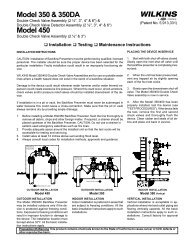
I DESCRIPTION AND OPERATION<br />
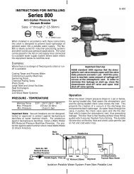
The RPZ device consists of two independently acting,<br />
spring loaded, poppet type check valves, together<br />
with a hydraulically dependent, mechanically<br />
independent pressure differential relief valve, located<br />
in the zone between the check valves. Two resilient<br />
seated shut-off valves and four test cocks complete<br />
the assembly.<br />
During normal operation, the pressure drop across the<br />
first check valve into the “zone” area is approximately<br />
7 PSI. The second check valve is lightly spring loaded<br />
to provide a minimum pressure drop of 1 PSI across<br />
it. (See Fig. 1)<br />
The relief valve operates on a differential pressure.<br />
<strong>Supply</strong> pressure on the upstream side of the first<br />
check valve acts against the diaphragm to close the<br />
relief valve during normal operation. In the event of<br />
back-pressure, the relief valve will open to maintain<br />
the pressure in the “zone” at least 2 PSI less than the<br />
inlet pressure.<br />
Flow<br />
(No Flow Condition)<br />
FIGURE 1<br />
REDUCED PRESSURE DETECTOR ASSEMBLY (RPDA)<br />
The RPDA device consists of a mainline RPZ and a<br />
by-pass assembly consisting of an approved RPZ<br />
assembly and water meter. Each device is equipped<br />
with test cocks for periodic field testing and is<br />
normally supplied with inlet and outlet shut-off valves.<br />
For information on operation, installation, trouble<br />
shooting & testing refer to Installation Instruction<br />
Booklet I503600 furnished with each RPDA unit. For<br />
maintenance instructions see pages 5 & 6. For parts<br />
list see pages 21 - 24.<br />
2
II INSTALLATION<br />
(a) The RPZ device must be installed in an accessible<br />
location to facilitate periodic field testing and<br />
maintenance.<br />
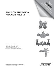
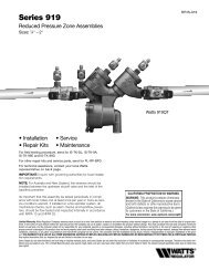
(b) The location selected should have adequate<br />
drainage for relief valve discharge. Drainage may<br />
be piped away, providing an approved air gap<br />
device is used (see Fig. 2). The device should<br />
never be placed where it may become submerged<br />
in standing water.<br />
(c) Flush all upstream piping thoroughly to remove<br />
foreign matter prior to installing the device.<br />
(d) Install the device in a horizontal position with<br />
adequate clearance from walls and/or<br />
obstructions, for testing and maintenance. A 12" to<br />
30" clearance between the lower most portion of<br />
the device and flood grade or floor should be<br />
provided.<br />
(e) When shut-off valves are supplied separately, they<br />
should be installed with a test cock on the<br />
upstream side of the inlet shut-off valve.<br />
(f) A “Y” strainer can be installed just upstream of the<br />
RPZ assembly to eliminate any debris from<br />
entering the device and fouling the check and/or<br />
relief valve.<br />
(g) When installing the assembly, use pipe sealant on<br />
external threads only (if applicable).<br />
(h) Use wrench grips provided when installing (if<br />
applicable).<br />
(i) After installing the assembly, and with downstream<br />
or #2 shut-off valve closed, pressurize the RPZ<br />
device and bleed air through test cock #4. Then<br />
open #2 shut-off valve.<br />
NOTE:<br />
If water continues to drain from the relief valve,<br />
check the Trouble Shooting section for probable<br />
causes and solutions.<br />
FIGURE 2<br />
3
III TROUBLE SHOOTING GUIDE<br />
SYMPTOM<br />
CAUSE<br />
CORRECTIVE ACTION<br />
1. Relief valve continuously<br />
discharges during no-flow<br />
condition.<br />
2. Relief valve discharges<br />
continuously during flow<br />
and no-flow conditions.<br />
3. Relief valve discharges<br />
intermittently in a<br />
“spitting” action during<br />
no-flow condition.<br />
4. Relief valve does not open<br />
during field test No. 1.<br />
5. #2 check valve fails to<br />
hold backpressure.<br />
6. Pressure differential<br />
across #1 check valve is<br />
low during field test No. 3<br />
(does not meet 3 PSID<br />
minimum).<br />
a. #1 check valve fouled with<br />
debris.<br />
b. #2 check valve fouled with<br />
debris coupled with a<br />
backpressure condition.<br />
c. #1 check poppet stem not<br />
moving freely in guide (or<br />
#2 check poppet during a<br />
backpressure condition.)<br />
a. Relief valve fouled with<br />
debris.<br />
b. Damaged diaphragm<br />
(allows water to pass<br />
through from inlet to zone).<br />
c. Sensing passage to inlet<br />
side of diaphragm plugged.<br />
d. #1 check poppet stem not<br />
moving freely in poppet<br />
guide.<br />
a. Pressure fluctuations (water<br />
hammer) from supply.<br />
a. #2 shut-off valve not<br />
closed completely.<br />
b. Test equipment improperly<br />
installed.<br />
a. #2 shut-off valve not<br />
closed completely.<br />
b. #2 check valve fouled with<br />
debris.<br />
c. #2 check poppet stem not<br />
moving freely in guide.<br />
a. #1 check valve fouled with<br />
debris.<br />
b. Upstream pressure<br />
fluctuations causing<br />
inaccurate gauge reading.<br />
c. #1 check poppet stem not<br />
moving freely in guide.<br />
a. Inspect and clean seat<br />
disc and seat.<br />
b. Inspect and clean seat<br />
disc and seat.<br />
c. Inspect for debris or<br />
deposit on poppet stem or<br />
guide.<br />
a. Inspect and clean relief<br />
valve seat disc and seat.<br />
b. Replace diaphragm.<br />
c. Inspect and clean passage<br />
in cover and body.<br />
d. Inspect for debris or<br />
deposits on poppet stem<br />
or guide.<br />
a. Eliminate or reduce<br />
pressure fluctuations.<br />
a. Close #2 shut-off valve or<br />
inspect for possible<br />
through leakage.<br />
b. Recheck test procedure.<br />
a. Close #2 shut-off valve or<br />
inspect for possible<br />
through leakage.<br />
b. Inspect and clean seat<br />
disc and seat.<br />
c. Inspect for debris or<br />
deposits on poppet stem<br />
or guide.<br />
a. Inspect and clean seat<br />
disc and seat.<br />
b. Eliminate pressure<br />
fluctuations.<br />
c. Inspect for debris or<br />
deposits on poppet stem<br />
or guide.<br />
4
IV 1/4" - 2" MAINTENANCE INSTRUCTIONS<br />
A. Disassembly — Check Valves<br />
1. Close #2 shut off valve, then close #1 shut-off<br />
valve.<br />
2. Bleed pressure from the assembly by opening #2,<br />
#3, and #4 test cock.<br />
CAUTION:<br />
Caps are spring loaded and should be removed<br />
carefully to avoid personal injury.<br />
3. Unscrew cap using hex head provided.<br />
4. Remove spring and poppet assembly from the<br />
body.<br />
B. Disassembly — Check Valve Poppet<br />
CAUTION:<br />
Do not use pliers or other tools which may<br />
damage or scratch the plastic stem.<br />
1. Holding the poppet assembly in one hand,<br />
remove screw and retaining washer.<br />
2. Remove the seat disc.<br />
3. All parts should be carefully inspected for any<br />
damage or excessive wear and thoroughly rinsed<br />
in clean water prior to reassembly. Replace worn<br />
parts as necessary.<br />
C. Assembly — Check Valve Poppet<br />
1. Install new disc in poppet, secure disc with<br />
retaining washer and screw.<br />
NOTE:<br />
Due to symmetry of the disc, the old disc may be<br />
turned over to obtain an effective seal.<br />
D. Assembly — Check Valve<br />
1. Install the poppet assembly into the body.<br />
2. Install the spring (heavy spring, larger diameter<br />
wire, goes into #1 check valve) onto the poppet.<br />
3. Apply a thin coat of synthetic based lubricant on<br />
cap O-Ring.<br />
4. Guide cap over spring and poppet stem and<br />
tighten cap.<br />
E. Relief Valve Disassembly<br />
1. Remove cover bolts, cover and diaphragm.<br />
2. Grasp the diaphragm plate and pull the<br />
assembly straight out of the body.<br />
3. Holding the relief valve assembly in one hand,<br />
remove the screw and retaining washer.<br />
4. Remove the seat disc.<br />
5. Turn the assembly over, keeping the spring<br />
compressed by holding down on the diaphragm<br />
plate, remove the screw.<br />
6. Remove the diaphragm plate, spring and bushing<br />
from the R.V. stem.<br />
7. Remove the O-Ring from the R.V. stem.<br />
8. All parts should be carefully inspected for any<br />
damage or excessive wear and thoroughly rinsed<br />
in clean water prior to reassembly. Replace worn<br />
parts as necessary.<br />
F. Assembly — Relief Valve<br />
1. Apply a thin coat of synthetic base lubricant on<br />
O-Rings before installing.<br />
2. Install O-Ring onto R.V. stem.<br />
3. Slide bushing over R.V. stem and position spring<br />
onto bushing.<br />
4. Position diaphragm plate and compress spring,<br />
install screw into R.V. stem.<br />
5. Turn the assembly over and install seat disc,<br />
retaining washer and screw.<br />
6. Install O-Ring onto bushing.<br />
7. Slide complete assembly into the body.<br />
8. Position diaphragm over flange, install cover and<br />
tighten bolts evenly.<br />
9. Open #1 shut-off valve & bleed air out of the unit<br />
through #2, #3 and #4 test cocks; then open #2<br />
shut-off valve.<br />
10.Test complete assembly to ensure proper operation.<br />
5
V 2-1/2" - 10" MAINTENANCE INSTRUCTIONS<br />
A. Disassembly — Check Valves<br />
C. Disassembly — Relief Valve<br />
1. Close #2 shut off valve, then close #1 shut-off valve. 1. Remove cover bolts, cover and diaphragm.<br />
2. Bleed pressure from the assembly by opening #2, NOTE:<br />
#3, and #4 test cock.<br />
On the 8" & 10" units the diaphragm is an integral<br />
3. Remove cover bolts and cover.<br />
part of the relief valve assembly.<br />
NOTE:<br />
2. Grasp the diaphragm plate and pull the assembly<br />
The spring load on the cover will be removed when straight out of the body.<br />
the cover bolts are backed off approximately 3/8". 3. Holding the relief valve assembly in one hand,<br />
4. Remove the complete check assembly straight out remove the screw and retaining washer.<br />
of the valve body being careful not to damage the 4. Remove the seat disc.<br />
seat ring.<br />
5. Turn the assembly over, keeping the spring<br />
5. The check valve seat is threaded into the body and compressed by holding down on the diaphragm<br />
may be removed at this time if necessary (the seat plate, remove the screw/bolt.<br />
is bolted into the body on the 10"unit).<br />
6. Remove the diaphragm plate(s), spring and<br />
6. To remove the seat disc, remove the retaining plate bushing from the R.V. stem.<br />
nut (on the 8" & 10" units remove the retaining 7. Remove the O-Ring from the R.V. stem.<br />
plate bolts) and retaining plate, remove disc.<br />
8. All parts should be carefully inspected for any<br />
WARNING:<br />
damage or excessive wear and thoroughly rinsed<br />
The check valve spring is held in compression by in clean water prior to reassembly. Replace worn<br />
the stem nut on top. This nut should not be<br />
parts as necessary.<br />
removed unless the spring requires replacement. D. Assembly — Relief Valve<br />
B. Assembly — Check Valves<br />
1. Apply a thin coat of synthetic base lubricant on<br />
1. Install seat disc in holder and secure with retaining O-Rings before installing.<br />
plate and retaining nut or bolts as applicable. 2. Install O-Ring onto R.V. stem.<br />
NOTE:<br />
3. Slide bushing over R.V. stem and position spring<br />
Due to the symmetry of the disc, the old disc may onto bushing.<br />
be turned over to obtain an effective seal.<br />
4. Position diaphragm plate(s) and compress spring,<br />
2. Install the check valve assembly into the body<br />
install screw into R.V. stem.<br />
(assemble with the larger diameter spring into the 5. Turn the assembly over and install seat disc,<br />
first check valve).<br />
retaining washer and screw.<br />
3. Apply a thin coat of synthetic based lubricant on 6. Install O-Ring onto bushing.<br />
the cover O-Ring and place it into the groove<br />
around the lip of the check barrel. Being careful not<br />
7. Slide complete assembly into the body testing for<br />
to disturb O-Ring, install the cover and tighten the freedom of movement.<br />
bolts evenly.<br />
8. Position diaphragm over flange ensuring that the<br />
hole in the diaphragm for the sensing passage is in<br />
the correct position, install cover and tighten bolts<br />
evenly.<br />
9. Open #1 shut-off valve & bleed air out of the unit<br />
through #2, #3 and #4 test cocks; then open #2<br />
shut-off valve.<br />
10.Test complete assembly to ensure proper operation.<br />
6
VI TESTING PROCEDURES<br />
IT'S IMPORTANT THAT THE RPZ BE TESTED<br />
PERIODICALLY IN COMPLIANCE WITH LOCAL<br />
CODES, BUT AT LEAST ONCE A YEAR OR MORE,<br />
AS SERVICE CONDITIONS WARRANT.<br />
EQUIPMENT REQUIRED<br />
Conbraco reduced pressure backflow preventer<br />
test kit <strong>40</strong>-<strong>200</strong>-TKU, or <strong>40</strong>-<strong>200</strong>-TK5U.<br />
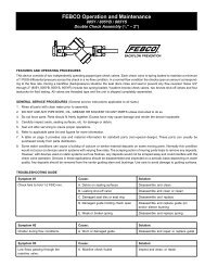
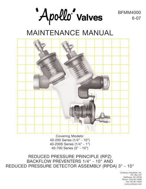
TEST NO. 1:<br />
NOTE: Test set-up is illustrated in Figure 3.<br />
PROCEDURE 1 for use with <strong>40</strong>-<strong>200</strong>-TKU Test Kit<br />
only. See procedure 2 for <strong>40</strong>-<strong>200</strong>-TK5U.<br />
Purpose:<br />
To test operation of the pressure differential relief<br />
valve.<br />
Requirement:<br />
The pressure differential relief valve must operate to<br />
maintain the “zone” between the two check valves at<br />
a minimum of 2 PSI less than the supply pressure.<br />
PROCEDURE:<br />
1. Bleed water through all four test cocks to flush any<br />
foreign material.<br />
NOTE: Open test cock #2 very slowly to avoid<br />
accidental dumping of the relief valve.<br />
2. Connect the “high” side hose to test cock #2.<br />
Connect the “low” side hose to test cock #3.<br />
3. Open valves #1, #2, and #3.<br />
4. Slowly open test cock #3 and bleed all air from<br />
gauge and hoses through the "vent" hose. With<br />
test cock #3 maintained in the open position,<br />
slowly open test cock #2 and bleed all air again<br />
through the "vent" hose. Close valve #3. Then<br />
close valve #2.<br />
5. Close #2 shut-off valve.<br />
6. Slowly open valve #3 until the differential gauge<br />
needle starts to drop.<br />
NOTE: It is important that the differential gauge<br />
needle drops slowly. Maintain #3 at this position<br />
and observe the differential pressure reading at the<br />
moment the first discharge is noted from the relief<br />
valve.<br />
7. Record this reading as the opening differential<br />
pressure of the relief valve and close valve #3.<br />
TEST NO. 2:<br />
Purpose:<br />
To test check valve #2 for tightness against<br />
reverse flow.<br />
Requirement:<br />
The check valve shall permit no through leakage in a<br />
direction reverse to normal flow under all conditions of<br />
a pressure differential.<br />
PROCEDURE:<br />
1. Maintain the #2 shut-off valve in the closed<br />
position (from Test No. 1).<br />
2. Loosely attach the “vent” hose to test cock #4.<br />
3. Bleed all air from the “vent” hose by opening<br />
valve #2.<br />
4. Close valve #2 and tighten hose connection to test<br />
cock #4. Then open test cock #4.<br />
5. Loosen the "low" side hose at test cock #3 slightly<br />
and re-establish the normal reduced pressure<br />
within the zone. Then retighten hose.<br />
6. Open valve #2. If the differential pressure remains<br />
steady then check valve #2 is reported as "OK". If<br />
the differential pressure falls until the relief valve<br />
opens then check valve #2 is recorded as "leaking"<br />
and Test No. 3 cannot be completed.<br />
TEST NO. 3:<br />
Purpose:<br />
To test the static differential pressure across check<br />
valve #1.<br />
Requirement:<br />
The static differential pressure across check valve #1<br />
must be a minimum of 3 PSI more than the opening<br />
differential pressure of the relief valve as recorded in<br />
Test No. 1.<br />
PROCEDURE:<br />
1. With the testing equipment installed as stated in<br />
Test No. 2, the static differential pressure across<br />
check valve #1 will be indicated on the gauge and<br />
should be recorded as such.<br />
NOTE: Gauge needle should be steady and not falling.<br />
RESTORE OPERATION:<br />
Close all test cocks, open all needle-valves, open #2<br />
shut-off valve and carefully remove all test equipment.<br />
NOTE: Refer to Troubleshooting Guide in section III to<br />
resolve any problems incurred during field testing.<br />
7
CONBRACO REDUCED PRESSURE<br />
BACKFLOW PREVENTER<br />
FIGURE 3<br />
(TOP VIEW SHOWN)<br />
8
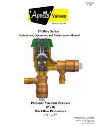
PROCEDURE 2<br />
TEST PROCEDURE USING <strong>40</strong>-<strong>200</strong>-TK5 or <strong>40</strong>-<strong>200</strong>-TKRC TEST KIT<br />
NOTE: IT IS THE TESTER’S RESPONSIBILITY TO DETERMINE IF THIS PROCEDURE IS ACCEPTED BY<br />
LOCAL AUTHORITIES.<br />
CONBRACO REDUCED PRESSURE<br />
BACKFLOW PREVENTER<br />
FIGURE 4<br />
(TOP VIEW SHOWN)<br />
TEST SET UP<br />
1. Obtain permission to shut off the water supply.<br />
2. Determine the direction of flow.<br />
3. Identify and install appropriate adapters in all 4<br />
test cocks.<br />
4. All test kit valves are closed.<br />
TEST NO. 1 - DOES THE DIFFERENTIAL PRES-<br />
SURE RELIEF VALVE OPERATE TO MAINTAIN THE<br />
“ZONE” BETWEEN THE TWO CHECK VALVES AT<br />
LEAST 2 PSI LESS THAN THE SUPPLY PRESSURE.<br />
1. Open test cock 4 to establish flow through the RP.<br />
“Blow out” test cocks 1, 2 & 3.<br />
Note: Open test cock 2 slowly to avoid accidental<br />
dumping of the relief valve. Close test cock 4.<br />
2. Connect the red hose between test cock 2 and the<br />
high side (back, middle) connection on the test kit.<br />
3. Connect the green hose between test cock 3<br />
and the low side (back, right) connection on the<br />
test kit.<br />
4. Slowly open test cock 3. Bleed the low side by<br />
opening the bleed low (top, right) valve.<br />
5. Slowly open test cock 2. Bleed the high side by<br />
opening the bleed high (top, left) valve. Close the<br />
bleed high (top, left) valve.<br />
6. After the gauge reaches full scale, close the bleed<br />
low (top, right) valve.<br />
7. Close the No. 2 shutoff valve and observe the<br />
pressure drop across Check Valve 1. Should the<br />
pressure drop until the relief valve discharges<br />
continuously, check valve 1 is leaking and must be<br />
repaired before continuing.<br />
8. Open the high (bottom, middle, red) valve.<br />
9. Open the low (bottom, right, green) valve no more<br />
than one quarter (1/4) turn.<br />
9
10.Watch the gauge drop slowly to the relief valve<br />
opening point - record the reading. (If the<br />
differential pressure does not drop to the relief<br />
valve opening point, close the high and low valves<br />
and go to step 12).<br />
11.Close the high and low valves and go to test No. 2.<br />
12.No. 2 shutoff valve may be leaking. Reopen and<br />
close No. 2 shutoff valve to attempt a better shutoff.<br />
Repeat steps 7 through 10. If the relief valve<br />
does not open, a by-pass hose is required. (Large<br />
leaks may require a garden hose).<br />
13.Attach a hose (not supplied with Test Kit) to test<br />
cock 1. Bleed hose by opening test cock 1. Close<br />
test cock 1.<br />
14.Connect the hose from test cock 1 to test cock 4.<br />
15.Open test cock 1 to pressurize the hose.<br />
16.Slowly open test cock 4. Repeat steps 8 through<br />
10. If the relief valve does not open, the leaky No.<br />
2 shutoff valve must be repaired.<br />
TEST NO. 2 - IS CHECK VALVE 2 PRESSURE<br />
TIGHT AGAINST BACK PRESSURE.<br />
NO BYPASS HOSE USED IN TEST 1.<br />
1. Connect the black hose to vent (back, left)<br />
connection on the test kit.<br />
2. Bleed vent hose by opening the high (bottom,<br />
middle, red) and vent (bottom, left, black) valves.<br />
Close the vent valve.<br />
3. Attach the vent hose to test cock 4.<br />
4. Open test cock 4.<br />
5. Open the bleed low (top, right) valve allowing the<br />
gauge to reach full scale. Close the bleed low<br />
valve.<br />
6. Open the vent (bottom, left, black) valve.<br />
7. If the differential pressure stabilizes above the relief<br />
valve opening point check valve 2 is recorded as<br />
“tight”. (Proceed to test No. 3). If the reading falls<br />
to the relief valve opening point, check valve 2 is<br />
recorded as “leaking” and Test No. 3 cannot be<br />
completed.<br />
BYPASS HOSE USED IN TEST 1.<br />
1. Leave the bypass hose connected between test<br />
cocks 1 and 4.<br />
2. Leave test cocks 1 and 4 open.<br />
3. Open the bleed low (top, right) valve allowing the<br />
gauge to reach full scale. Close the bleed low<br />
valve.<br />
4. If the differential pressure stabilizes above the relief<br />
valve opening point, check valve 2 is recorded as<br />
“tight”. (Proceed to Test No. 3). If the reading falls<br />
to the relief valve opening point, check valve 2 is<br />
recorded as “leaking” and Test No. 3 cannot be<br />
completed.<br />
TEST NO. 3 - IS THE STATIC PRESSURE DROP<br />
ACROSS CHECK VALVE 1 MAINTAINED AT LEAST 3<br />
PSI ABOVE THE RELIEF VALVE OPENING POINT.<br />
1. Open the bleed low (top, right) valve allowing the<br />
gauge to reach full scale. Close the bleed low<br />
valve.<br />
2. Allow the gauge reading to stabilize. Record this<br />
reading as the static pressure drops across check<br />
valve 1.<br />
3. Close all test cocks. Open the No. 2 shutoff valve.<br />
Remove all test equipment. Drain test kit.<br />
10
VII PARTS LISTING 1/4" - 2" (Bronze)<br />
3<br />
7<br />
10<br />
21<br />
18<br />
15<br />
16<br />
13<br />
23<br />
24<br />
2<br />
8<br />
1<br />
25<br />
17<br />
26<br />
23<br />
27<br />
19<br />
6<br />
14<br />
12<br />
4<br />
11<br />
5<br />
9<br />
22<br />
20<br />
Inlet and Outlet Shut-Off Valves<br />
<strong>40</strong>-20X-TX<br />
Size 1/4” 3/8” 1/2” 3/4” 1” 1-1/4” 1-1/2” 2”<br />
Inlet Shut-Off Valve<br />
7B80101 7B80201 7B80301 7B80<strong>40</strong>1 7B80501 7B80699A 7B80799A 7B80899A<br />
Inlet Shut-Off Valve w/Union<br />
7B30301 7B30<strong>40</strong>1 7B30501 7B30699A 7B30799A 7B30899A<br />
Test Cock 7825701 7825701 7825701 7825701 7825701 7825701 7825701 7825701<br />
Outlet Shut-Off Valve 7B80131 7B80231 7B80331 7B80431 7B80531 7B80699B 7B80799B 7B80899B<br />
Outlet Shut-Off Valve w/Union<br />
7B30331 7B30431 7B30531 7B30699B 7B30799B 7B30899B<br />
Replacement Handles for<br />
Shut-Off Valves W858800 W858800 W858800 W858800 W859100 W891500 W891600 W891600<br />
11
<strong>40</strong>-<strong>200</strong><br />
Reduced Pressure Principle <strong>Backflow</strong> Preventer<br />
ITEM NO. DESCRIPTION QUANTITY PART NO.<br />
1/4", 3/8", 1/2" 3/4" & 1" 1 1/4", 1 1/2", 2"<br />
1 Body 1 Consult Consult Consult<br />
Factory Factory Factory<br />
2 R.V. Cover 1 F301705 F298205 F298505<br />
3 Cap 2 F323105 F310805 F311505<br />
4 R.V. Bushing 1 I450715 I42<strong>40</strong>15 I425715<br />
5 R.V. Stem 1 G329600 G321<strong>200</strong> G321300<br />
6 Diaphragm Plate 1 E222<strong>200</strong> D250600 D251600<br />
7 Poppet 2 K3<strong>40</strong>900 K336<strong>200</strong> K336700<br />
8 R.V. Diaphragm 1 D263<strong>200</strong> D250500 D251500<br />
9 R.V. Seat Disc 1 D263100 D282900 D251<strong>40</strong>0<br />
10 Check Seat Disc 2 D263000 D250300 D250800<br />
11 Stem O-Ring 1 D262800 D250<strong>200</strong> D251300<br />
12 Bushing O-Ring 1 D262900 D250100 D251<strong>200</strong><br />
13 Check Cap O-Ring 2 D204600 D250000 D251000<br />
14 R.V. Spring 1 A179500 A169800 A170<strong>200</strong><br />
15 1st Check Spring 1 A179700 A169900 A170300<br />
16 2nd Check Spring 1 A179<strong>40</strong>0 A170000 A170100<br />
17 Hex Head Bolt 6(*4) (**7) B179300 B175100 B175<strong>40</strong>0<br />
18 Screw 2 B183700 B175000 B175000<br />
19 Screw 1 B174900 B174900 B175300<br />
20 Screw 1 B183700 B174800 B175300<br />
21 Retaining Washer 2 E222300 D249900 D250900<br />
22 Retaining Washer 1 E222<strong>40</strong>0 D249800 D249900<br />
23 Test Cock 3 7825701 7825701 7825801<br />
24 Check Seat 2 L515<strong>200</strong> L486<strong>40</strong>0 L486600<br />
25 Check O-Ring 2 D308600 D227<strong>40</strong>0 D256500<br />
26 R.V. Seat 1 L515300 L486300 L486700<br />
27 R.V. O-Ring 1 D308700 D216800 D227<strong>40</strong>0<br />
O-Ring Lubricant 1 I901600 I901600 I901600<br />
Repair Kits***<br />
Major Repair Kit<br />
4, 5, 6, 7 (2), 8, 9, 10 (2), 11, 12,<br />
13 (2), 14, 18 (2), 19, 20, 21 (2), 22, <strong>40</strong>003A1 <strong>40</strong>004A1 <strong>40</strong>007A1<br />
24 (2), 25 (2), 26, 27<br />
Check Valve Repair Kit<br />
7, 10, 13, 18, 21, 24, 25 <strong>40</strong>003A2 <strong>40</strong>004A2 <strong>40</strong>007A2<br />
Relief Valve Repair Kit<br />
4, 5, 6, 8, 9, 11, 12, 14, 19, 20, 22, <strong>40</strong>003A3 <strong>40</strong>004A3 <strong>40</strong>007A3<br />
26, 27<br />
Rubber Repair Kit<br />
8, 9, 10 (2), 11, 12, 13 (2), 25 (2), 27 <strong>40</strong>003A4 <strong>40</strong>004A4 <strong>40</strong>007A4<br />
Replaceable Seat Kit<br />
24 (2), 25 (2), 26, 27 <strong>40</strong>003A7 <strong>40</strong>004A7 <strong>40</strong>007A7<br />
Accessories<br />
Air Gap Drain <strong>40</strong><strong>200</strong>XA <strong>40</strong><strong>200</strong>X1 <strong>40</strong><strong>200</strong>X1<br />
Seat Removal Tool <strong>40</strong>000SRT <strong>40</strong>000SRT <strong>40</strong>000SRT<br />
Reduced Pressure <strong>Backflow</strong> Preventer Test Kit <strong>40</strong><strong>200</strong>TKU, <strong>40</strong><strong>200</strong>TK5U, or <strong>40</strong><strong>200</strong>TKRC (All Sizes)<br />
* 1/4", 3/8" & 1/2" SIZES ONLY<br />
** 1-1/4", 1-1/2" & 2" SIZES ONLY<br />
*** For repair kits without replaceable seat components, replace part number suffix designation “A” with “O”.<br />
Example: Major Repair Kit part number <strong>40</strong>00<strong>40</strong>1<br />
12
VIII PARTS LISTING 1/4" - 1" (Stainless Steel)<br />
3<br />
7<br />
10<br />
15<br />
13<br />
23<br />
21<br />
18<br />
16<br />
24<br />
2<br />
8<br />
1<br />
25<br />
17<br />
26<br />
23<br />
27<br />
19<br />
6<br />
14<br />
12<br />
4<br />
11<br />
5<br />
9<br />
22<br />
20<br />
Inlet and Outlet Shut-Off Valves<br />
<strong>40</strong>-20X-T2S<br />
Size 1/4” 3/8” 1/2” 3/4” 1”<br />
Inlet Shut-Off Valve<br />
7H80101 7H80201 7H80301 7H80<strong>40</strong>1 7H80501<br />
Test Cock 7893001 7893001 7893001 7893001 7893001<br />
Outlet Shut-Off Valve 7H80131 7H80231 7H80331 7H80431 7H80531<br />
Replacement Handles for<br />
Shut-Off Valves<br />
W858800 W858800 W858800 W858800 H269300<br />
13
<strong>40</strong>-<strong>200</strong>S<br />
Stainless Steel Reduced Pressure Principle<br />
<strong>Backflow</strong> Preventer<br />
ITEM NO. DESCRIPTION QUANTITY PART NO.<br />
1/4", 3/8", 1/2" 3/4" & 1"<br />
1 Body 1 Consult Consult<br />
Factory<br />
Factory<br />
2 R.V. Cover 1 F305605 F304805<br />
3 Cap 2 F323205 F323305<br />
4 R.V. Bushing 1 I514915 I510515<br />
5 R.V. Stem 1 G329600 G321<strong>200</strong><br />
6 Diaphragm Plate 1 E222<strong>200</strong> D250600<br />
7 Poppet 2 K3<strong>40</strong>900 K336<strong>200</strong><br />
8 R.V. Diaphragm 1 D308800 D304700<br />
9 R.V. Seat Disc 1 D263100 D282900<br />
10 Check Seat Disc 2 D263000 D250300<br />
11 Stem O-Ring 1 D308<strong>40</strong>0 D305100<br />
12 Bushing O-Ring 1 D308500 D304<strong>40</strong>0<br />
13 Check Cap O-Ring 2 D308300 D305<strong>200</strong><br />
14 R.V. Spring 1 A179500 A169800<br />
15 1st Check Spring 1 A179700 A169900<br />
16 2nd Check Spring 1 A179<strong>40</strong>0 A170000<br />
17 Hex Head Bolt 4(*6) B179300 B175100<br />
18 Screw 2 B183700 B174800<br />
19 Screw 1 B174900 B174900<br />
20 Screw 1 B183700 B175000<br />
21 Retaining Washer 2 E222300 D249900<br />
22 Retaining Washer 1 E222<strong>40</strong>0 D249800<br />
23 Test Cock 3 7893001 7893001<br />
24 Check Seat 2 L515<strong>200</strong> L486<strong>40</strong>0<br />
25 Check O-Ring 2 D308600 D304600<br />
26 R.V. Seat 1 L515300 L486300<br />
27 R.V. O-Ring 1 D308700 D304500<br />
O-RIng Lubricant 1 I901600 I901600<br />
Repair Kits<br />
Major Repair Kit<br />
4, 5, 6, 7 (2), 8, 9, 10 (2), 11, 12,<br />
13 (2), 14, 18 (2), 19, 20, 21 (2), 22, <strong>40</strong>003A1S <strong>40</strong>004A1S<br />
24 (2), 25 (2), 26, 27<br />
Check Valve Repair Kit<br />
7, 10, 13, 18, 21, 24, 25 <strong>40</strong>003A2S <strong>40</strong>004A2S<br />
Relief Valve Repair Kit<br />
4, 5, 6, 8, 9, 11, 12, 14, 19, 20, 22, <strong>40</strong>003A3S <strong>40</strong>004A3S<br />
26, 27<br />
Rubber Repair Kit<br />
8, 9, 10 (2), 11, 12, 13 (2), 25 (2), 27 <strong>40</strong>003A4S <strong>40</strong>004A4S<br />
Replaceable Seat Kit<br />
24 (2), 25 (2), 26, 27 <strong>40</strong>003A7S <strong>40</strong>004A7S<br />
Accessories<br />
Air Gap Drain <strong>40</strong><strong>200</strong>XA <strong>40</strong><strong>200</strong>X1<br />
Seat Removal Tool <strong>40</strong>000SRT <strong>40</strong>000SRT<br />
Reduced Pressure <strong>Backflow</strong> Preventer Test Kit <strong>40</strong><strong>200</strong>TKU, <strong>40</strong><strong>200</strong>TK5U, or <strong>40</strong><strong>200</strong>TKRC<br />
(All Sizes)<br />
* 3/4", 1" SIZES ONLY<br />
14
IX PARTS LISTING 2-1/2" - 10" (Ductile Iron)<br />
2-1/2" - 3" - 4" RPZ (<strong>Model</strong> <strong>40</strong>-<strong>200</strong> <strong>Series</strong>)<br />
(shown without relief valve)<br />
15
RPZ (<strong>Model</strong> <strong>40</strong>-<strong>200</strong> <strong>Series</strong>)<br />
Parts List<br />
ITEM NO. DESCRIPTION QUANTITY PART NO.<br />
2-1/2" 3" 4"<br />
1 Shut-Off Valve (OS&Y) 2 W678900 W679000 W682<strong>40</strong>0<br />
1 Shut-Off Valve (NRS) 2 W678500 W678600 W674300<br />
2 Brass Nipple 1 K3<strong>40</strong>600 K3<strong>40</strong>600 K3<strong>40</strong>600<br />
3 Test Cock 1 7010301 7010301 7010301<br />
4 Flange Nut * C169100 C169100 C169100<br />
5 Ring Gasket 2 D258300 D258<strong>40</strong>0 D258<strong>200</strong><br />
6 Flange Bolt * B180<strong>40</strong>0 B180<strong>40</strong>0 B182800<br />
7 Body 1 Q452819 Q452919 Q453219<br />
8 Nameplate 1 I4<strong>40</strong>600 I4<strong>40</strong>600 I4<strong>40</strong>600<br />
9 Drive Screw 2 I261300 I261300 I261300<br />
10 C.V. Seat O-Ring 2 D256700 D256700 D257300<br />
11 C.V. Seat 2 L463705 L463705 L46<strong>40</strong>05<br />
12 C.V. Stem 2 G323906 G323906 G324206<br />
13 C.V. Stem O-Ring 2 D256100 D256100 D256100<br />
14 Retainer Nut 2 C175600 C175600 C175600<br />
15 Retainer Washer 2 E219900 E219900 E220<strong>40</strong>0<br />
16 C.V. Seat Disc 2 D256000 D256000 D257<strong>200</strong><br />
17 Seat Disc Holder 2 F300005 F300005 F300105<br />
18 1st Check Spring 1 A17<strong>40</strong>00 A17<strong>40</strong>00 A174300<br />
19 2nd Check Spring 1 A174100 A-174100 A174<strong>40</strong>0<br />
20 Spring Retainer 2 E219805 E219805 E220205<br />
21 Jam Nut 2 C158905 C158905 C158905<br />
22 Cap O-Ring 2 D256600 D256600 D257<strong>40</strong>0<br />
23 C.V. Cap 2 Q453019 Q453019 Q453319<br />
24 Cap Bolt 12 B179700 B179700 B180100<br />
25 Test Cock 3 7080301 7080301 7080301<br />
* 2-1/2" & 3" QTY = 8 / 4" QTY = 16<br />
16
6" - 8" - 10" RPZ (<strong>Model</strong> <strong>40</strong>-<strong>200</strong> <strong>Series</strong>)<br />
(shown without relief valve)<br />
17
RPZ (<strong>Model</strong> <strong>40</strong>-<strong>200</strong> <strong>Series</strong>)<br />
Parts List<br />
ITEM NO. DESCRIPTION QUANTITY PART NO.<br />
6" 8" 10"<br />
1 Shut-Off Valve (OS&Y) 2 W682500 W682600 W685900<br />
1 Shut-Off Valve (NRS) 2 W674<strong>40</strong>0 W682700 W685800<br />
2 Brass Nipple 1 K3412<strong>40</strong> K341<strong>200</strong> K341<strong>200</strong><br />
3 Test Cock 1 7010<strong>40</strong>1 7010<strong>40</strong>1 7010<strong>40</strong>1<br />
4 Flange Nut * C175900 C175900 C179300<br />
5 Ring Gasket 3 D257900 D259000 D265300<br />
6 Flange Bolt ** B182900 B185700 B185800<br />
6A Stud 2 N/A N/A B203600<br />
7 Body 1 Q453819 Q454319 Q457219<br />
7A Body 1 Q459119 Q459319 Q459519<br />
8 Nameplate 1 I4<strong>40</strong>600 I4<strong>40</strong>600 I4<strong>40</strong>600<br />
9 Drive Screw 2 I261300 I261300 I261300<br />
10 C.V. Seat O-Ring 2 D256700 D258900 D258800<br />
11 C.V. Seat 2 L464<strong>40</strong>5 L465305 L475905<br />
12 C.V. Stem 2 G324600 G327300 G330500<br />
13 C.V. Stem O-Ring 2 D257800 D258700 D258700<br />
14 Retainer Nut/Bolt *** C176000 C175<strong>40</strong>0 C175<strong>40</strong>0<br />
15 Retainer Washer 2 E220500 E220800 E222900<br />
16 C.V. Seat Disc 2 D257500 D258600 D264900<br />
17 Seat Disc Holder 2 F300205 F300805 F301905<br />
18 1st Check Spring 1 A174500 A174700 A177800<br />
19 2nd Check Spring 1 A174600 A174800 A177900<br />
20 Spring Retainer 2 E220305 E220705 E222805<br />
21 Jam Nut 2 C170600 *C176305 *C176305<br />
22 Cap O-Ring 2 D257700 D258800 D265100<br />
23 C.V. Cap 2 Q453719 Q454519 Q457419<br />
24 Cap Bolt **** B180000 B169000 B188100<br />
25 Test Cock 3 7080<strong>40</strong>1 7080<strong>40</strong>1 7080<strong>40</strong>1<br />
Seat Bolt 12 N/A N/A B184900<br />
* 6" & 8" QTY = 24 / 10" QTY = 38<br />
** 6" & 8" QTY = 24 / 10" QTY = 34<br />
*** 6" QTY = 2 / 8" & 10" QTY = 8<br />
**** 6" QTY = 12 / 8" & 10" QTY = 24<br />
18
2-1/2" - 6" Relief Valves<br />
8" & 10" Relief Valves<br />
19
Continued from page 18<br />
RPZ (<strong>Model</strong> <strong>40</strong>-<strong>200</strong> <strong>Series</strong>)<br />
Parts List<br />
ITEM NO. DESCRIPTION QUANTITY PART NO. QUANTITY PART NO.<br />
2-1/2" - 6" 8", 10"<br />
Repair Kits<br />
26 Relief Valve Cover Bolt 7 B179600 7 B170300<br />
27 1/2 NPT Plug 1 K300800 N/A N/A<br />
27 3/4 NPT Plug N/A N/A 1 K301000<br />
28 Relief Valve Cover 1 Q453105 1 Q454219<br />
29 Relief Valve Diaphragm 1 D256<strong>40</strong>0 1 D259100<br />
30 Relief Valve Seat Ring 1 L463805 1 L465105<br />
31 Relief Valve Seat Ring O-Ring 1 D256800 1 D2593-00<br />
32 Relief Valve Body 1 Q453505 1 Q454119<br />
33 Small Relief Valve O-Ring 1 D257000 1 D218600<br />
34 Large Relief Valve O-Ring 1 D257100 1 D230<strong>40</strong>0<br />
35 Relief Valve Flange Bolt 2 B180000 4 B166900<br />
36 1/4 NPT Plug 1 K301900 1 K301900<br />
37 Relief Valve Flange Bolt 2 B179<strong>200</strong> 2 B166900<br />
38 Pan Head Screw 2 B175300 1 B185600<br />
39 Relief Valve Seat Washer 1 E2<strong>200</strong>00 1 E221000<br />
<strong>40</strong> Relief Valve Seat Disc 1 D256300 1 D259500<br />
41 Relief Valve Stem 1 G32<strong>40</strong>00 1 G327<strong>40</strong>5<br />
42 Relief Valve Stem O-Ring 1 D256500 1 D259<strong>40</strong>0<br />
43 Relief Valve Bushing O-Ring 1 D256<strong>200</strong> 1 D259<strong>200</strong><br />
44 Relief Valve Bushing 1 L463915 1 L465215<br />
45 Relief Valve Spring 1 A174<strong>200</strong> 1 A174900<br />
46 Diaphragm Plate 1 E220100 2 E220905<br />
47 Stem Face O-Ring N/A N/A 1 D210600<br />
48 Diaphragm Bolt N/A N/A 1 B180000<br />
PART NO.<br />
1st Check Valve Repair Kit 2-1/2", 3" 4" 6" 8" 10"<br />
12, 13, 14, 15, 16, 17, 18, 20, 21, 22 <strong>40</strong>00901 <strong>40</strong>00A01 <strong>40</strong>00C01 <strong>40</strong>00E01 <strong>40</strong>00G01<br />
2nd Check Valve Repair Kit<br />
12, 13, 14, 15, 16, 17, 19, 20, 21, 22 <strong>40</strong>00902 <strong>40</strong>00A02 <strong>40</strong>00C02 <strong>40</strong>00E02 <strong>40</strong>00G02<br />
Seat Repair Kit<br />
10, 11, 22 <strong>40</strong>00903 <strong>40</strong>00A03 <strong>40</strong>00C03 <strong>40</strong>00E03 <strong>40</strong>00G03<br />
Rubber Repair Kit<br />
10, 13, 16, 22 <strong>40</strong>00904 <strong>40</strong>00A04 <strong>40</strong>00C04 <strong>40</strong>00E04 <strong>40</strong>00G04<br />
Relief Valve Repair Kit<br />
29, 30, 31, 33, 34, 38, 39, <strong>40</strong>, 41, 42, 43, <strong>40</strong>00905 <strong>40</strong>00A05 <strong>40</strong>00C05 <strong>40</strong>00E05 <strong>40</strong>00G05<br />
44, 45, 46, (47, 48)*<br />
Relief Valve Rubber Repair Kit<br />
29, 31, 33, 34, <strong>40</strong>, 42, 43, (47)* <strong>40</strong>00906 <strong>40</strong>00A06 <strong>40</strong>00C06 <strong>40</strong>00E06 <strong>40</strong>00G06<br />
*8" & 10" Only<br />
20
NOTES:<br />
1. USE P/N W-7062-00 FOR METER IN CUBIC FEET REGISTER.<br />
USE P/N W-7094-00 FOR METER IN GALLONS REGISTER.<br />
2. N/S - NOT SHOWN<br />
3" - 4"<br />
RPDA By-Pass Assembly Kits:<br />
3” RPDA w/meter in cubic feet <strong>40</strong>700BPC<br />
3” RPDA w/meter in gallons <strong>40</strong>700BPE<br />
4” RPDA w/meter in cubic feet <strong>40</strong>70ABPC<br />
4”RPDA w/meter in gallons <strong>40</strong>70ABPE<br />
21
RPDA (<strong>Model</strong> <strong>40</strong>-700 <strong>Series</strong>)<br />
Parts List<br />
ITEM NO. DESCRIPTION QUANTITY PART NO.<br />
3" 4"<br />
1 Gate Valve (OS&Y) 2 W679000 W682<strong>40</strong>0<br />
2 RPDA Body 1 Q493419 Q480719<br />
3 Relief Valve Ass’y 1 W672905 W672905<br />
4 Test Cock 3 7080301 7080301<br />
N/S 1st Chk Poppet Ass’y 1 W671705 W673005<br />
N/S 2nd Chk Poppet Ass’y 1 W728905 W710005<br />
7 By-Pass Shut-Off Valve 1 7B10<strong>40</strong>1 7B10<strong>40</strong>1<br />
8 Tee, Reducing 1 K350600 K350600<br />
9 Coupling, Water Meter 2 K350500 K350500<br />
10 Water Meter in Cubic Feet 1 W706<strong>200</strong> W706<strong>200</strong><br />
10 Water Meter in Gallons 1 W709<strong>40</strong>0 W709<strong>40</strong>0<br />
11 3/4" RPZ 1 W739005 W739005<br />
12 Elbow, Street * K350<strong>200</strong> K350<strong>200</strong><br />
13 By-Pass Shut-Off Valve 1 7B10431 7B10431<br />
14 Nipple, Close 4 K337000 K337000<br />
15 Test Cock 1 7010301 7010301<br />
N/S Flange Nut ** C143800 C143800<br />
17 Flange Gasket 2 D258<strong>40</strong>0 D258<strong>200</strong><br />
18 Flange Bolt ** B180<strong>40</strong>0 B182800<br />
19 Cap 2 Q453019 Q453319<br />
20 Cap Bolt 12 B179700 B180100<br />
21 Relief Valve Flange Bolt (Lg.) 2 B180000 B180000<br />
22 Relief Valve Flange Bolt (Sm.) 2 B179<strong>200</strong> B179<strong>200</strong><br />
23 Nipple 1 K3<strong>40</strong>600 K3<strong>40</strong>600<br />
24 Test Cock 1 7825701 7825701<br />
N/S Nipple, 3/4" x 4-1/2" (Lg.) 1 K360500 N/A<br />
N/S Elbow, 3/4" - 90º 1 K350100 N/A<br />
N/S Cap O-Ring 2 D256600 D257<strong>40</strong>0<br />
N/S Seat O-Ring 2 D256700 D257300<br />
N/S Relief Valve O-Ring (Sm.) 1 D257000 D257000<br />
N/S Relief Valve O-Ring (Lg.) 1 D257100 D257100<br />
N/S Nameplate 1 I499100 I499100<br />
N/S Nameplate Tack 2 I529<strong>40</strong>0 I529<strong>40</strong>0<br />
N/S Instruction Booklet 1 I503600 I503600<br />
N/S Check Valve Seat 2 L463705 L46<strong>40</strong>05<br />
* 3" QTY = 3 / 4" QTY = 1<br />
** 3" QTY = 8 / 4" QTY = 16<br />
22
NOTES:<br />
1. USE P/N W-7062-00 FOR METER IN CUBIC FEET REGISTER.<br />
USE P/N W-7094-00 FOR METER IN GALLONS REGISTER.<br />
2. N/S - NOT SHOWN<br />
6" - 10"<br />
8<br />
RPDA By-Pass Assembly Kits:<br />
6” RPDA w/meter in cubic feet <strong>40</strong>70CBPC<br />
6” RPDA w/meter in gallons <strong>40</strong>70CBPE<br />
8” RPDA w/meter in cubic feet <strong>40</strong>70EBPC<br />
8”RPDA w/meter in gallons <strong>40</strong>70EBPE<br />
10” RPDA w/meter in cubic feet <strong>40</strong>70GBPC<br />
10”RPDA w/meter in gallons <strong>40</strong>70GBPE<br />
23
RPDA<br />
Parts List<br />
ITEM NO. DESCRIPTION QUANTITY PART NO.<br />
6" 8" 10"<br />
1 Gate Valve (OS&Y) 2 W682500 W682600 W685900<br />
2 Body (1st Check) 1 Q453819 Q454319 Q457219<br />
3 Body (2nd Check) 1 Q459119 Q459319 Q459519<br />
4 Relief Valve Ass’y 1 W672905 W674805 W674805<br />
5 Test Cock 3 7080<strong>40</strong>1 7080<strong>40</strong>1 7080<strong>40</strong>1<br />
N/S 1st Chk Poppet Ass’y 1 W674105 W674505 W685605<br />
N/S 2nd Chk Poppet Ass’y 1 W720605 W720705 W724905<br />
8 By-Pass Shut-Off Valve 1 7B10<strong>40</strong>1 7B10<strong>40</strong>1 7B10<strong>40</strong>1<br />
9 Tee, 3/4" NPT 1 K351100 K351100 K351100<br />
10 Coupling, Water Meter 2 K350500 K350500 K350500<br />
11 Water Meter in Cubic Feet 1 W706<strong>200</strong> W706<strong>200</strong> W706<strong>200</strong><br />
11 Water Meter in Gallons 1 W709<strong>40</strong>0 W709<strong>40</strong>0 W709<strong>40</strong>0<br />
12 3/4" RPZ 1 W739005 W739005 W739005<br />
13 Elbow, 3/4" NPT 1 K350100 K350100 K350100<br />
14 By-Pass Shut-Off Valve 1 7B80431 7B80431 7B80431<br />
15 Nipple, 3/4" NPT 2 K350900 K352700 K356000<br />
16 Test Cock 1 7010<strong>40</strong>1 7010<strong>40</strong>1 7010<strong>40</strong>1<br />
17 Flange Nut * C175900 C175900 C179300<br />
18 Flange Gasket 3 D257900 D259000 D265300<br />
19 Flange Bolt ** B182900 B185700 B185800<br />
20 Cap 2 Q453719 Q454519 Q457419<br />
21 Cap Bolt *** B180000 B169000 B188100<br />
22 Relief Valve Flange Bolt (Lg.) **** B180000 B166900 B166900<br />
23 Relief Valve Flange Bolt (Sm.) 2 B179<strong>200</strong> B166900 B166900<br />
24 Nipple, 3/4" NPT 1 K341<strong>200</strong> K341<strong>200</strong> K341<strong>200</strong><br />
25 Nipple, 3/4" x 5-1/2" (Lg.) 1 K350900 K350900 K350900<br />
26 Nipple, 3/4" NPT 1 K350900 K350900 K355900<br />
27 Test Cock 1 7825701 7825701 7825701<br />
N/S Elbow, 3/4" - 90º 1 K350100 K350100 K350100<br />
N/S Cap O-Ring 2 D257700 D258800 D265100<br />
N/S Seat O-Ring 2 D257600 D258900 D258800<br />
N/S Relief Valve O-Ring (Sm.) 1 D257000 D218600 D218600<br />
N/S Relief Valve O-Ring (Lg.) 1 D257100 D230<strong>40</strong>0 D230<strong>40</strong>0<br />
N/S Nameplate 1 I499100 I499100 I499100<br />
N/S Nameplate Tack 2 I529<strong>40</strong>0 I529<strong>40</strong>0 I529<strong>40</strong>0<br />
N/S Instruction Booklet 1 I503600 I503600 I503600<br />
N/S Check Valve Seat 2 L464<strong>40</strong>5 L465305 L475905<br />
N/S Stud 2 N/A N/A B203600<br />
N/S Seat Bolt 12 N/A N/A B184900<br />
* 6" & 8" QTY = 24 / 10" QTY = 38<br />
** 6" & 8" QTY = 24 / 10" QTY = 34<br />
*** 6" QTY = 12 / 8" & 10" QTY = 24<br />
**** 6" QTY = 2 / 8" & 10" QTY = 4<br />
24
BACKFLOW PREVENTER TEST KITS<br />
DESCRIPTION<br />
The Conbraco <strong>Backflow</strong> Preventer Test Kits are compact, lightweight and portable testing devices. They come<br />
equipped with a gauge, hoses and all required adapter fittings. Also included is a flexible or adjustable strap for<br />
hanging the gauge, laminated test procedures and a molded plastic carrying case with foam inserts.<br />
DIFFERENTIAL PRESSURE GAUGE TEST KIT <strong>40</strong>-<strong>200</strong>-TKU<br />
This is a three valve test kit used for testing all DCV, RPZ,<br />
PVB & SVB backflow preventers.<br />
The gauge is a differential pressure type with a dual scale of<br />
0-15 psid/0-100kPa differential pressure range with a ± 2%<br />
accuracy (full scale).<br />
<strong>40</strong>-<strong>200</strong>-TK5U<br />
This five valve kit is used for testing all DCV, RPZ, PVB & SVB<br />
backflow preventers.<br />
The five valve test kit is similar to the three valve kit except it<br />
has an additional two valves that make it possible to bleed<br />
lines without disconnecting hoses.<br />
MODEL APPLICATION WT./100 (lbs)<br />
<strong>40</strong>-<strong>200</strong>-TKU ALL DCV, RPZ, PVB & SVB 780<br />
<strong>40</strong>-<strong>200</strong>-TK5U ALL DCV, RPZ, PVB & SVB 650<br />
25
NOTES<br />
26
Manufactured by Conbraco Industries, Inc.<br />
SALES AND SERVICE DEPARTMENT<br />
P.O. Box 247 • Matthews, NC 28106<br />
Phone: 704-841-6000 • Fax: 704-841-6020<br />
E-Mail Address Phone Fax<br />
Southeast<br />
Region<br />
Southern<br />
Region<br />
Midwestern Region<br />
Western Region<br />
Northeast<br />
Region<br />
Canada<br />
Int’l./<br />
Puerto Rico<br />
B. Lynch & Associates Florida sales@blynchandassociates.com 813-792-5060 813-792-5213<br />
Spotswood Associates Georgia/Alabama dlewis@spotswoodassociates.com 770-447-1227 770-263-6899<br />
Pro Marketing, Inc. North Carolina/South Carolina/Tennessee-East sales@promarketinginc.net 864-578-4334 864-578-4889<br />
Mid South Marketing, Inc. Virginia/Maryland/Washington, D.C./WV-East midsouth7@aol.com 804-213-3801 804-213-3802<br />
Southern Marketing Group MS/TN-West/AR/Bowie Cty.-TX SMG49@bellsouth.net 901-547-0042 901-547-0035<br />
AVC Mechanical Sales, Inc. Oklahoma/Texas-North valvesales@avalve.com 214-201-0100 214-201-0104<br />
Armstrong/Weatherly Associates Texas-South/Louisiana sales@armstrong-weatherly.com 713-692-5566 713-692-6021<br />
HEBCO, Inc. Kansas/Missouri-West kcwinelvr@aol.com 913-491-0797 913-491-5126<br />
New Tech Marketing IL/WI-East/IN-North/MI-Upper Peninsula/IA-/River Counties ntm012@mcleodusa.net 630-378-4300 630-378-0343<br />
New Tech Marketing Eastern Missouri/Southern Illinois ntm112@aol.com 618-394-0329 618-394-0427<br />
Whitfill-McCarthy, LLC Kentucky/Indiana-South/Ohio-South whitfill@win.net 502-459-4545 502-459-9944<br />
V.E. Sales Co., Inc. Michigan (Except Upper Peninsula) tomv@vesalesinc.com 586-774-7760 586-774-1490<br />
Northstar Valve & Fitting, Inc. Minnesota/North & South Dakota/Wisconisn-West northstarvalve@qwest.net 952-937-0108 952-937-0803<br />
WilIco, Inc. Nebraska/Iowa (Except River Counties) bill@willcoinc.com <strong>40</strong>2-573-7000 <strong>40</strong>2-573-7371<br />
Midwest Spec Ohio-North/Pennsylvania-West/West Virginia-West glsales@mwspec.com 330-538-0<strong>40</strong>6 330-538-0410<br />
Elmco and Associates California-North kkleinen@elmcoassoc.com 916-383-0110 916-383-0181<br />
Cisco Speciality Products, Inc. California-South ciscoemail@aol.com 714-921-9228 714-921-0442<br />
SPEC Management Hawaii-all products (S. California; Irrigation only) msmarch4@cox.net 949-481-4225 949-487-0990<br />
Marshall-Rodeno Associated CO/WY/MT/ID-SE/UT/NV-NE/NM/El Paso-TX trodeno@marshallrodeno.com 303-575-6701 303-575-6706<br />
Braley-Gray & Associates Oregon/SW Washington/Western Idaho sales@braleygray.com 503-249-6972 503-288-4464<br />
Braley-Gray Washington Alaska/Washington info@braleygray.com 206-<strong>40</strong>5-4370 206-<strong>40</strong>5-4390<br />
Southwestern Industrial Sales Co. Arizona/Nevada-SW eduardop@sw-ind.com 480-458-5838 480-458-5843<br />
Urell, Inc. Massachusetts/New England States conbraco@urell.com 617-923-9500 617-926-9414<br />
McMahon Marketing, Inc. New York-Upstate/New York-West sales@mcmahonmarketing.com 518-792-3350 518-792-3351<br />
Continuous Sales Corporation New York-East/New Jersey-North csc07@aol.com 516-575-6800 516-349-8411<br />
Cope-Wardell-Ammon Associates Pennsylvania-East/Delaware/New Jersey-South joejr@cwaassociates.com 610-485-2828 610-485-7171<br />
Keith Engle & Associates OEM accounts keith.engle@verizon.net 610-827-9560 610-827-9561<br />
Conbraco Industries, Canada 160 Pennsylvania Ave., Unit 3, Concord, Ontario L4K 4A9 conbraco.canada@conbraco.com 905-761-6161 905-761-6666<br />
Barclay Sales Ltd. British Columbia bbarclay@barclaysales.com 604-945-1010 604-945-3030<br />
Dynamic Agencies, Ltd. Saskatchewan doug.dynamicage@sasktel.net 306-343-1901 306-343-1901<br />
Tom Beggs Agencies Ltd. Manitoba/NW Ontario TBA@MB.SYMPATICO.CA 204-953-1900 204-774-6915<br />
Task Controls, Inc. Ontario infotoronto@taskcontrols.com 416-291-3004 416-754-3481<br />
Agences J. Pierre Sylvain, Inc. Quebec agencespsylvain@golden.net 450-655-9588 450-641-2737<br />
Kern Industries, Ltd. Alberta-North kernind@telusplanet.net 780-451-2056 780-454-6687<br />
Kern Industries Calgary, Ltd. Alberta-South kerncalgary@telus.net <strong>40</strong>3-730-7791 <strong>40</strong>3-239-8179<br />
J. Levandier Sales, Inc. Nova Scotia, New Brunswick, Prince Edward Island jlssales@istar.ca 506-858-1615 506-858-1084<br />
Smith Agencies Newfoundland smithagencies@nl.rogers.com 709-364-8856 709-747-9414<br />
Key to the North Sales Agency, Inc. Ontario-North hmehes@keytothenorth.ca 705-524-6714 705-566-0148<br />
Steam and Industrial Equipment Ottawa sie@sie.ca 1-800-363-8482 514-457-7111<br />
Rafael Rodriguez Barril, Inc. Puerto Rico rauli@rrbarril.com 787-982-1550 787-982-1570<br />
Conbraco International Limited Manchester, England sales@conbraco.co.uk 44-161-212-3745 +44-161-212-3747<br />
Conway, SC • Matthews, NC • Pageland, SC • Customer Service 1-704-841-6000 • www.conbraco.com<br />
Printed in USA COPYRIGHT 6/07<br />
BFMM<strong>40</strong>00<br />
DKG 5M