Geology, Soils, and Seismicity - Contra Costa County
Geology, Soils, and Seismicity - Contra Costa County
Geology, Soils, and Seismicity - Contra Costa County

Create successful ePaper yourself
Turn your PDF publications into a flip-book with our unique Google optimized e-Paper software.
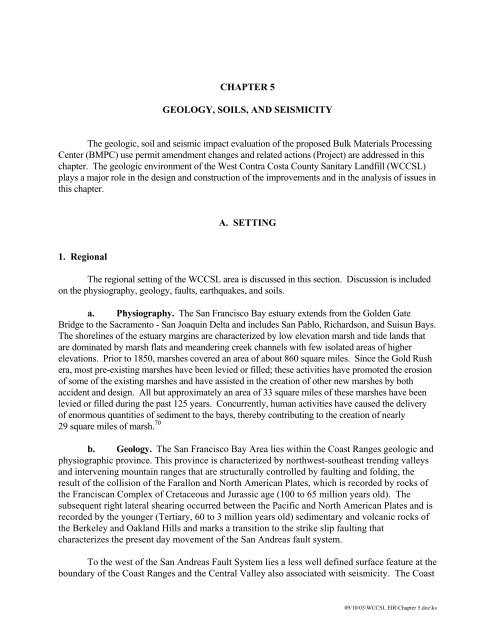
CHAPTER 5<br />
GEOLOGY, SOILS, AND SEISMICITY<br />
The geologic, soil <strong>and</strong> seismic impact evaluation of the proposed Bulk Materials Processing<br />
Center (BMPC) use permit amendment changes <strong>and</strong> related actions (Project) are addressed in this<br />
chapter. The geologic environment of the West <strong>Contra</strong> <strong>Costa</strong> <strong>County</strong> Sanitary L<strong>and</strong>fill (WCCSL)<br />
plays a major role in the design <strong>and</strong> construction of the improvements <strong>and</strong> in the analysis of issues in<br />
this chapter.<br />
A. SETTING<br />
1. Regional<br />
The regional setting of the WCCSL area is discussed in this section. Discussion is included<br />
on the physiography, geology, faults, earthquakes, <strong>and</strong> soils.<br />
a. Physiography. The San Francisco Bay estuary extends from the Golden Gate<br />
Bridge to the Sacramento - San Joaquin Delta <strong>and</strong> includes San Pablo, Richardson, <strong>and</strong> Suisun Bays.<br />
The shorelines of the estuary margins are characterized by low elevation marsh <strong>and</strong> tide l<strong>and</strong>s that<br />
are dominated by marsh flats <strong>and</strong> me<strong>and</strong>ering creek channels with few isolated areas of higher<br />
elevations. Prior to 1850, marshes covered an area of about 860 square miles. Since the Gold Rush<br />
era, most pre-existing marshes have been levied or filled; these activities have promoted the erosion<br />
of some of the existing marshes <strong>and</strong> have assisted in the creation of other new marshes by both<br />
accident <strong>and</strong> design. All but approximately an area of 33 square miles of these marshes have been<br />
levied or filled during the past 125 years. Concurrently, human activities have caused the delivery<br />
of enormous quantities of sediment to the bays, thereby contributing to the creation of nearly<br />
29 square miles of marsh. 70<br />
b. <strong>Geology</strong>. The San Francisco Bay Area lies within the Coast Ranges geologic <strong>and</strong><br />
physiographic province. This province is characterized by northwest-southeast trending valleys<br />
<strong>and</strong> intervening mountain ranges that are structurally controlled by faulting <strong>and</strong> folding, the<br />
result of the collision of the Farallon <strong>and</strong> North American Plates, which is recorded by rocks of<br />
the Franciscan Complex of Cretaceous <strong>and</strong> Jurassic age (100 to 65 million years old). The<br />
subsequent right lateral shearing occurred between the Pacific <strong>and</strong> North American Plates <strong>and</strong> is<br />
recorded by the younger (Tertiary, 60 to 3 million years old) sedimentary <strong>and</strong> volcanic rocks of<br />
the Berkeley <strong>and</strong> Oakl<strong>and</strong> Hills <strong>and</strong> marks a transition to the strike slip faulting that<br />
characterizes the present day movement of the San Andreas fault system.<br />
To the west of the San Andreas Fault System lies a less well defined surface feature at the<br />
boundary of the Coast Ranges <strong>and</strong> the Central Valley also associated with seismicity. The Coast<br />
09/10/03\WCCSL EIR\Chapter 5.doc\ks
5-2<br />
Ranges-Central Valley (CRCV) geomorphic boundary is formed by an active fold <strong>and</strong> thrust<br />
fault zone that generally does not break the surface. 85<br />
Although the bedrock record indicates a long history of deformation, the present day<br />
topography is controlled by movement of the San Andreas fault zone <strong>and</strong> abrupt changes in the<br />
climate. The geology of the San Francisco <strong>and</strong> San Pablo Bay margins is controlled by the<br />
interactions of the Quaternary (past 2 million years) climatological sea level fluctuations <strong>and</strong> the<br />
vertical tectonic deformation of the shorelines. This interaction of tectonics <strong>and</strong> sea level has<br />
controlled the advance <strong>and</strong> retreat of the Bay’s shorelines resulting in their very distinct sequence of<br />
sediments.<br />
The Soil Survey of <strong>Contra</strong> <strong>Costa</strong> <strong>County</strong> (<strong>County</strong>) indicates the native soils in the vicinity of<br />
the WCCSL site are Reyes Silty Clay. 97 These soils are found in salt marsh environments affected<br />
by tides <strong>and</strong> are characterized by very poor drainage. Natural slopes are less than 1 percent <strong>and</strong><br />
elevation is at or near sea level. Vegetation is pickelweed, saltgrass, <strong>and</strong> some sedges. These soils<br />
are always moist with a high water table <strong>and</strong> are subject to inundation by tides.<br />
c. Faults. The WCCSL is located within the San Francisco Bay Area, which lies at<br />
the edge of a major plate tectonic boundary between the North American <strong>and</strong> Pacific Plates.<br />
This boundary is defined by the San Andreas fault zone. There are several known active faults<br />
in the vicinity of the project site. Active faults, as included in the Alquist Priolo Earthquake<br />
Fault Zones, are characterized by displacement of Holocene deposits (soil or rock less than<br />
11,000 years old), evidence of fault creep <strong>and</strong>/or well defined seismic activity on traces of<br />
known faults.<br />
The major active, strike-slip faults in the area are part of the San Andreas Fault System,<br />
which includes the San Andreas, Hayward, Greenville, Green Valley-Concord, <strong>and</strong> the Calaveras<br />
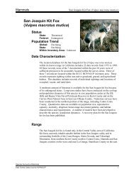
faults. These <strong>and</strong> other faults of the region are shown on Figure 5-1. For the active faults within<br />
a 61-mile radius, the distance from the central Class II L<strong>and</strong>fill area <strong>and</strong> estimated maximum<br />
Moment magnitude event, are summarized in Table 5-1. 74,91 Moment magnitude is an energybased<br />
scale <strong>and</strong> provides a physically meaningful measure of the size of a faulting event.<br />
Moment magnitude is directly related to average slip <strong>and</strong> fault rupture area.<br />
<strong>Seismicity</strong>. The WCCSL is located in one of the most seismically active regions in the<br />
nation. A listing of earthquakes of magnitude 5.0 <strong>and</strong> greater occurring since 1800 in the San<br />
Francisco Bay area are presented in Table 5-2.<br />
09/10/03\WCCSL EIR\Chapter 5.doc\ks
5-3<br />
61 mile radius<br />
31 miles<br />
Source: reference 74 <strong>and</strong> 91.<br />
Figure 5-1 Map of Major Faults <strong>and</strong> Earthquake<br />
Epicenters in the San Francisco Bay Area
5-4<br />
Table 5-1. Regional Faults <strong>and</strong> <strong>Seismicity</strong><br />
Maximum<br />
Fault<br />
Approximate<br />
distance from<br />
WCCSL, miles<br />
Direction from<br />
WCCSL<br />
magnitude<br />
(maximum credible<br />
earthquake)<br />
Hayward (Total) 2.6 Northeast 7.1<br />
Hayward (North) 2.6 Northeast 6.6<br />
Rodgers Creek 9 North 7.1<br />
San Andreas (1906 Event) 15 Southwest 7.9<br />
San Andreas (Peninsula) 15 Southwest 7.2<br />
West Napa 15 Northeast 6.5<br />
San Gregorio (North) 16 West 7.3<br />
Hayward (South) 17 Southeast 6.9<br />
Concord 17 East 6.5<br />
Green Valley (South) 17 East 6.5<br />
Mount Diablo Thrust 20 East 6.7<br />
Calaveras (North) 21 East 7.0<br />
Point Reyes 24 West 6.8<br />
Greenville (North) 31 East 6.6<br />
Green Valley (North) 25 Northeast 6.3<br />
Great Valley – 6 27 East 6.7<br />
Great Valley – 5 28 Northeast 6.5<br />
Great Valley – 4 29 Northeast 6.6<br />
Greenville (Central) 33 East 6.7<br />
Hunting Creek – Berryessa 35 North 6.9<br />
Monte Vista 37 South 6.8<br />
Greenville (South) 44 Southeast 6.9<br />
Hayward (Southeast Extension) 44 Southeast 6.4<br />
Maacama (South) 44 North 6.9<br />
Great Valley – 7 47 Southeast 6.7<br />
Calaveras (Central) 48 Southeast 6.6<br />
Great Valley – 3 48 North 6.8<br />
Collayomi 57 North 6.5<br />
San Andreas (Santa Cruz Mountains) 58 South 7.2<br />
Source: References 74 <strong>and</strong> 91.<br />
09/10/03\WCCSL EIR\Chapter 5.doc\ks
5-5<br />
Table 5-2. Post-1800 Earthquakes with Magnitudes<br />
Larger than 5.0 in the Greater Bay Area<br />
Date<br />
Approximate distance from<br />
WCCSL, miles<br />
Approximate<br />
magnitude<br />
June 1, 1838 25 7.5<br />
January 2, 1856 33 5.3<br />
February 15, 1856 33 5.5<br />
November 26, 1858 42 6.1<br />
July 4, 1861 24 5.6<br />
February 26, 1864 70 5.9<br />
March 5, 1864 28 5.7<br />
May 21, 1864 29 5.3<br />
October 8, 1865 53 6.3<br />
October 21, 1868 24 7.0<br />
May 19, 1889 26 6.0<br />
April 19, 1892 36 6.4<br />
March 31, 1898 16 6.2<br />
April 18, 1906 19 7.9<br />
July 1, 1911 56 6.6<br />
September 5, 1955 52 5.5<br />
October 24, 1955 18 5.4<br />
March 22, 1957 21 5.3<br />
October 2, 1969 37 5.7<br />
January 24, 1980 33 5.8<br />
January 27, 1980 38 5.4<br />
April 24, 1984 59 6.2<br />
March 31, 1986 50 5.7<br />
June 13, 1988 52 5.3<br />
June 27, 1988 64 5.3<br />
August 8, 1989 62 5.4<br />
October 17, 1989 69 6.9<br />
Source: reference 82.<br />
09/10/03\WCCSL EIR\Chapter 5.doc\ks
5-6<br />
Since 1800, four major earthquakes have been recorded on the San Andreas Fault as<br />
follows:<br />
• In 1836, an earthquake with an estimated maximum intensity of VII on the<br />
Modified Mercalli (MM) scale occurred east of Monterey Bay on the San<br />
Andreas Fault. The estimated Moment magnitude (M w ) for this<br />
earthquake is about 6.3. 82<br />
• In 1838, an earthquake occurred with an estimated intensity of about<br />
VIII-IX (MM), corresponding to a M w of about 7.5.<br />
• The San Francisco earthquake of 1906 caused the most significant damage<br />
in the history of the Bay Area in terms of loss of lives <strong>and</strong> property<br />
damage. This earthquake created a surface rupture along the San Andreas<br />
Fault from Shelter Cove to San Juan Bautista approximately 250 miles in<br />
length <strong>and</strong> a maximum lateral displacement of 21 feet. It had a maximum<br />
intensity of XI (MM), an M w of about 7.9 with an epicenter approximately<br />
15 miles southwest of the WCCSL, <strong>and</strong> was felt 344 miles away in<br />
Oregon, Nevada, <strong>and</strong> Los Angeles.<br />
• The most recent earthquake to affect the Bay Area was the Loma Prieta<br />
earthquake of October 17, 1989, in the Santa Cruz Mountains with a M w<br />
of 6.9, approximately 69 miles south of the WCCSL.<br />
The Vacaville-Winters earthquake of 1892 occurred on the CRCV boundary<br />
approximately 29 miles north of the WCCSL, <strong>and</strong> had an estimated magnitude of 6.8<br />
(M w ). 75,83 Two after shocks were reported in 1892 of magnitudes 5.8 <strong>and</strong> 6.4 in the<br />
vicinity of Vacaville. Other activity on the CRCV includes a magnitude 6.3 event near<br />
Antioch, approximately 12 miles northeast of the site in 1889, <strong>and</strong> a magnitude 5.9 event<br />
in Paterson, approximately 45 miles southeast of the site in 1866.<br />
In 1999, the Working Group on California Earthquake Probabilities (WGCEP) of the<br />
United States Geological Survey compiled the earthquake fault research for the San<br />
Francisco Bay Area in order to estimate the probability of fault segment rupture. They<br />
have estimated that the overall probability of a Richter magnitude 6.7 or greater<br />
earthquake occurring within the next 30 years is 70 percent. The highest probabilities are<br />
assigned to the San Francisco Peninsula segment of the San Andreas Fault <strong>and</strong> the<br />
northern Hayward/Rodgers Creek Faults (21 <strong>and</strong> 32 percent, respectively). The<br />
Calaveras Fault was assigned a probability of 18 percent, <strong>and</strong> the Greenville <strong>and</strong><br />
Concord-Green Valley faults were each assigned probabilities of 6 percent. 91<br />
Ground Rupture. The WCCSL site is located in the tectonically active San Francisco Bay<br />
region where historic ground rupture associated with earthquakes has occurred on several<br />
active faults <strong>and</strong>/or faults subsidiary to the main active traces. These ground ruptures were<br />
09/10/03\WCCSL EIR\Chapter 5.doc\ks
extensively documented for the 1906 San Francisco Earthquake <strong>and</strong> for earthquakes since<br />
that time. However, several earthquakes that occurred during the early establishment of San<br />
Francisco Bay area are poorly documented.<br />
Seismic Effects. Earthquakes have primary <strong>and</strong> secondary effects, which are important<br />
considerations in the evaluation of the proposed Project. Primary effects include fault creep,<br />
the slow accumulation of strain sometimes measurable at the ground surface, <strong>and</strong> rapid<br />
earthquake-induced fault rupture <strong>and</strong> strong ground shaking. In the case of the strike slip<br />
faults of the San Francisco Bay Area, fault rupture <strong>and</strong> creep affect a narrow, roughly linear<br />
area of the ground surface. Strong ground shaking is the result of large magnitude<br />
earthquakes <strong>and</strong> can be felt over wide areas extending for tens to several hundred miles from<br />
the epicentral region.<br />
The secondary effects of earthquakes include vibrational damage to structures, liquefaction,<br />
l<strong>and</strong>slides, fissuring, lurching <strong>and</strong> lateral spreading. The active faults in the region that are<br />
capable of producing the most significant ground shaking at the WCCSL site are the<br />
Hayward <strong>and</strong> San Andreas faults. EMCON/OWT (consultants for West <strong>County</strong> L<strong>and</strong>fill,<br />
Inc. [Applicant]) presented median peak ground accelerations (PGAs) for rock of 0.52g <strong>and</strong><br />
0.22g for maximum credible earthquake (MCE) events on the Hayward (M w =7.1) <strong>and</strong> San<br />
Andreas Faults (M w =7.9). 52<br />
Intense groundshaking during a large earthquake should be expected at the WCCSL site.<br />
The actual ground motions depend on the magnitude of the earthquake, the distance to the<br />
source, <strong>and</strong> the local soil conditions. For sites within a few miles of a fault rupture, the<br />
intensity of the ground shaking also depends on the direction of fault rupture relative to the<br />
site. These are discussed further in the next section.<br />
Liquefaction is a “quicks<strong>and</strong>” condition that occurs when a loose, water-saturated s<strong>and</strong>y soil<br />
is subjected to dynamic loading that results in an increase of the pore water pressure <strong>and</strong><br />
subsequent loss of shear strength <strong>and</strong> liquid behavior. The s<strong>and</strong>y soils most susceptible to<br />
liquefaction are situated at shallow (less than about 50 feet) depths. The temporary high<br />
pore water pressures sometimes result in s<strong>and</strong>y material being transported along horizontal<br />
or vertical conduits through the surficial soils as s<strong>and</strong> boils or volcanoes. The consequences<br />
of liquefaction include vertical <strong>and</strong> lateral deformation, <strong>and</strong> loss of bearing. Normally firm,<br />
but wet, ground materials take on the characteristics of liquids. Liquefaction-induced lateral<br />
deformation can occur on sloping ground <strong>and</strong> along embankment slopes. Liquefaction<br />
potential of a saturated granular soil is dependent on its relative density, fines content,<br />
earthquake magnitude, <strong>and</strong> the level of shaking. A discussion of liquefaction relative to the<br />
Class II l<strong>and</strong>fill site is included in Section D of this chapter.<br />
Maximum Credible Earthquakes. The MCE is the maximum earthquake magnitude that<br />
could occur under the presently known geologic framework. The probability of occurrence<br />
of that event is not considered. State regulations (California Code of Regulations, Title 27<br />
[27 CCR]) require Class II L<strong>and</strong>fill facilities be designed to withst<strong>and</strong> the MCE without<br />
5-7<br />
09/10/03\WCCSL EIR\Chapter 5.doc\ks
5-8<br />
damage to the building foundations or to structures which contain leachate, surface drainage,<br />
extracted groundwater, or l<strong>and</strong>fill gas (LFG). A summary of the MCE for nearby active<br />
faults is included in Table 5-1.<br />
2. Project Site<br />
More site-specific information on the geologic setting of the WCCSL site is presented in this<br />
section.<br />
a. <strong>Geology</strong>. The WCCSL lies within a geologic province of the San Francisco Bay<br />
named the "Richmond Basin," bounded by the San Pablo <strong>and</strong> Hayward faults. Differential<br />
movement along these bounding faults has down dropped the area now occupied by the Bay <strong>and</strong><br />
uplifted the blocks containing the Berkeley <strong>and</strong> Oakl<strong>and</strong> Hills. This differential uplift probably<br />
occurred approximately 2 to 3 million years ago, during the early stages of movement on the<br />
Hayward fault. Interaction between the eroding sediments of the uplifting hills <strong>and</strong> fluctuating sea<br />
levels caused deposition of the multiple alluvial fans that coalesced to form the Bay marginal<br />
plain. 70,71 Bedrock "isl<strong>and</strong>s" that occur within this plain are the result of differential weathering<br />
caused by the rivers that intermittently flowed across the Bay floor during periods of lower sea level.<br />
b. Subsurface Conditions. As discussed below, the geologic units at the WCCSL site<br />
are typical for the areas of the bay margin, <strong>and</strong> include fill material (including L<strong>and</strong>fill deposits),<br />
Younger Bay Mud, Old Bay Mud <strong>and</strong> other sediments, overlying Franciscan Bedrock. This section<br />
presents a synopsis of the site stratigraphy (the order <strong>and</strong> position of strata, a bed or formation of<br />
sedimentary rock). The primary significance of the site stratigraphy for the proposed height increase<br />
<strong>and</strong> other improvements relates to compression, consolidation <strong>and</strong> strength of the waste <strong>and</strong> Young<br />
Bay Mud, which can result in settlement <strong>and</strong> slope stability problems.<br />
Numerous studies at the WCCSL have provided subsurface geotechnical <strong>and</strong> geologic data.<br />
The reported data include exploratory soil boring logs, well installation logs, <strong>and</strong> cone penetrometer<br />
test (CPT) soundings. CPTs are used to measure the relative stiffness of soil. Borings <strong>and</strong> CPTs<br />
were performed by various consultants, as referenced by Wahler (1994), <strong>and</strong> EMCON/OWT, Inc.<br />
(2003). The general stratigraphy beneath the Class II l<strong>and</strong>fill, including the existing <strong>and</strong> proposed<br />
waste, is discussed below. 52<br />
Fill Material. The artificial fill materials at the Class II l<strong>and</strong>fill primarily include municipal<br />
solid waste (including construction demolition debris <strong>and</strong> self-hauled waste), industrial<br />
waste, <strong>and</strong> sewage sludge. However, municipal solid waste (MSW) accounts for<br />
approximately 70 percent of the waste disposed. Clean soil is also present within the fill that<br />
was placed as intermediate <strong>and</strong> final cover layers. The l<strong>and</strong>fill is presently permitted for fill<br />
placement up to elevation 110 feet mean sea level (msl) on side slopes, gradually sloping up<br />
to a topdeck elevation of 130 feet msl. The fill was originally placed directly over the Bay<br />
Mud around elevation 0 feet msl, but it has since settled downward. The base of the refuse is<br />
currently between about elevation 0 <strong>and</strong> –20 feet msl. Therefore, the thickness of fill/waste<br />
09/10/03\WCCSL EIR\Chapter 5.doc\ks
at the site ranges from zero at the l<strong>and</strong>fill perimeter to about 150 to 160 feet near the centralwest<br />
side of the l<strong>and</strong>fill.<br />
Refuse thickness at the former Soil Remediation Building, as reviewed by Woodward-Clyde<br />
Consultants in 1995, is on the order of 15 to 30 feet, corresponding to between about<br />
elevations 18 <strong>and</strong> –5 feet msl. 90 Since that time, a fill pad about 17 feet high reinforced with<br />
geogrid was placed over the refuse for construction of the building. Significant settlement of<br />
the ground surface occurred, resulting in an irregular ground surface <strong>and</strong> damage to the<br />
building floor slab. 78<br />
Refuse is not present at Area A as it is outside of the Class II l<strong>and</strong>fill (Figure 3-1). Very little<br />
site-specific subsurface information is available for this location.<br />
A perimeter berm of clean fill surrounds the Class II l<strong>and</strong>fill site. The berm is on the order<br />
of 10 feet above adjacent grade. The bottom of the berm extends several feet below grade,<br />
as it has settled due to consolidation of the underlying compressible Bay Mud.<br />
Young Bay Mud. Young Bay Mud underlies the artificial fill beneath the Class II l<strong>and</strong>fill<br />
<strong>and</strong> is interbedded with s<strong>and</strong>y stream deposits. The Young Bay Mud (from here forth<br />
referred to as Bay Mud) consists of gray, soft <strong>and</strong> poorly consolidated, compressible, weak,<br />
organic-rich clayey silt to silty clay with moderate to high shrinkage potential. The age of<br />
the Bay Mud varies from approximately 9,600 years old to the most recent deposits which<br />
are still forming in the Bay. 70 The granular materials within the Bay Mud were deposited as<br />
streams flowed into st<strong>and</strong>ing water of San Pablo Bay. The s<strong>and</strong>y zones consist of fine silty<br />
s<strong>and</strong> to fine s<strong>and</strong>.<br />
The maximum known thickness of the Bay Mud at the Class II l<strong>and</strong>fill site is approximately<br />
70 feet at the east <strong>and</strong> northeast sides. The thickness is approximately 60 feet under the<br />
northern <strong>and</strong> western parts, <strong>and</strong> it varies from 40 to 50 feet along the southern parts of the<br />
l<strong>and</strong>fill. The Bay Mud is about 45 feet thick at the Soil Remediation Building location. The<br />
Bay Mud is generally interbedded with s<strong>and</strong> layers along the east, north, <strong>and</strong> western<br />
portions of the l<strong>and</strong>fill. The s<strong>and</strong> layers were not observed along most of the southern side<br />
of the site. S<strong>and</strong> layers up to 20 feet thick occur at depths greater than 100 feet below the<br />
site. Clean s<strong>and</strong>s were primarily observed on the north side of the WCCSL site along San<br />
Pablo Creek.<br />
Old Bay Mud, Sediments, <strong>and</strong> Bedrock. The Young Bay Mud at the site is underlain by a<br />
stiffer clay unit <strong>and</strong> other sediments. The clay unit likely corresponds to the unit known<br />
locally as Old Bay Mud or Old Bay Clay, however, there is some disagreement as to whether<br />
it is actually Old Bay Mud, or an older Holocene clay unit. 84 The Old Bay Mud extends<br />
from the bottom of the Young Bay Mud to an Elevation of about –135 feet msl, <strong>and</strong> varies<br />
from approximately 80 to 100 feet in thickness. It is primarily composed of clay <strong>and</strong> silty<br />
clay, <strong>and</strong> for the purpose of the settlement studies, is considered to be incompressible.<br />
5-9<br />
09/10/03\WCCSL EIR\Chapter 5.doc\ks
5-10<br />
The Old Bay Mud is underlain by old consolidated sediments consisting of alternating<br />
sequences of estuarine <strong>and</strong> alluvial deposits. These sediments are heterogeneous sequences<br />
of silt, clay, <strong>and</strong> s<strong>and</strong>. The sediments are underlain by Franciscan bedrock at depths of about<br />
150 to 300 feet below the original ground surface (approximately sea level); the actual<br />
bedrock depth at the Class II l<strong>and</strong>fill is not well defined.<br />
Groundwater. Groundwater levels within the l<strong>and</strong>fill range from about elevation 0 feet msl<br />
at the edges of the l<strong>and</strong>fill to about elevation 20 feet msl near the center of the l<strong>and</strong>fill. The<br />
water within the l<strong>and</strong>fill is composed of both natural groundwater <strong>and</strong> leachate from the<br />
MSW. Though desirable, an inward groundwater gradient toward the l<strong>and</strong>fill has not yet<br />
been achieved because the Applicant has been unable to pump high volumes of leachate to<br />
the West <strong>County</strong> Wastewater District (WCWD) Treatment Plant due to concerns over<br />
elevated levels of chloride salts. As discussed in Chapter 6, Section D3, however, a separate<br />
Class II l<strong>and</strong>fill leachate line to the WCWD sludge lagoons will be completed in late 2003.<br />
Class II leachate flows will then be routed directly to the City of Richmond Wastewater<br />
Treatment Plant. This will enable about 100,000 gallons per day of leachate to be pumped to<br />
the plant, thus greatly facilitating the establishment of an inward hydraulic gradient at the<br />
Class II l<strong>and</strong>fill.<br />
Leachate Containment Structures. The Bay Mud prevents the downward vertical<br />
migration of l<strong>and</strong>fill leachate. Horizontal migration of leachate is prevented by a lowpermeability<br />
vertical barriers, including a soil-attapulgite slurry wall separating the Class I<br />
<strong>and</strong> Class II l<strong>and</strong>fills, <strong>and</strong> a Bay Mud barrier wall that surrounds the entire WCCSL site.<br />
The soil-attapulgite slurry wall is 8 to 10 feet south of the former Soil Remediation Building<br />
site proposed for the location of the WRC. The wall was built in 1986 as a barrier between<br />
the Class I <strong>and</strong> Class II l<strong>and</strong>fill sites. The slurry wall was constructed to be about 5 feet<br />
wide, with the bottom of the wall keyed into the Bay Mud at elevation –10 feet msl. 90<br />
The Bay Mud barrier wall was constructed in 1977-78 <strong>and</strong> surrounds the entire WCCSL site.<br />
Because subsequent investigations indicated the presence of s<strong>and</strong> channels beneath the mud<br />
barrier, sections of the original Bay Mud barrier were replaced by a soil-cement-bentonite<br />
barrier. The Bay Mud barrier <strong>and</strong> the soil-cement-bentonite barrier have hydraulic<br />
conductivities of 1×10 -6 cm/s or less, a minimum thickness of 3 feet, <strong>and</strong> are keyed into the<br />
underlying Bay Mud at a minimum of 5 feet. 29 Hydraulic conductivities are a measure of a<br />
material’s ability to transmit water. A lower conductivity value indicates the migration of<br />
liquids is substantially restricted.<br />
Fault Occurrence. Active <strong>and</strong> potentially active faults that could have a significant impact<br />
on the Project facilities were previously discussed in Section A1.c of this chapter. However,<br />
another fault, the San Pablo Fault, has been mapped in the site vicinity based on bedrock<br />
outcrops <strong>and</strong> offshore features. This fault does not show any geomorphic features associated<br />
with Holocene surface displacements, has no seismicity associated with its trace <strong>and</strong> is not<br />
09/10/03\WCCSL EIR\Chapter 5.doc\ks
5-11<br />
considered active or potentially active by the California Geological Survey geologists <strong>and</strong> is,<br />
therefore, not considered seismogenic.<br />
B. REGULATORY AND PLANNING FRAMEWORK<br />
There are State of California, <strong>County</strong>, <strong>and</strong> City of Richmond (City) policies <strong>and</strong> regulations<br />
that form the regulatory <strong>and</strong> planning framework for geology, soils, <strong>and</strong> seismicity. A discussion of<br />
these policies <strong>and</strong> regulations is provided in this section. Because a Class II l<strong>and</strong>fill is a State of<br />
California designation, the California code supercedes the Federal code for this Project.<br />
1. State <strong>and</strong> Regional<br />
Applicable regulations from the 27 CCR <strong>and</strong> the Regional Water Quality Control Board<br />
(RWQCB) are summarized below.<br />
a. California Code of Regulations (27 CCR):<br />
• §20240(d). All engineered structures constituting any portion of a waste<br />
management unit shall have a foundation capable of providing support for the<br />
structures, capable of withst<strong>and</strong>ing hydraulic pressure gradients to prevent failure<br />
due to settlement, compression, or uplift, <strong>and</strong> all effects of ground motions resulting<br />
from at least the MCE for Class II units.<br />
• §20250(b). L<strong>and</strong>fills shall be immediately underlain with geologic materials with a<br />
hydraulic conductivity of not more than 1×10 -6 cm/sec <strong>and</strong> are sufficiently thick to<br />
prevent vertical movement of fluid to waters of the state. Natural or artificial barriers<br />
shall be used to prevent lateral movement of fluid.<br />
• §20250(d). New <strong>and</strong> exp<strong>and</strong>ed Class II units shall have a 200-foot setback from any<br />
known Holocene fault. [A Holocene-active fault has experienced movement within<br />
about the past 11,000 years.]<br />
• §20250(e). New <strong>and</strong> existing Class II units can be located within areas of potential<br />
rapid geologic change only if the RWQCB finds the unit’s containment structures<br />
can resist failure.<br />
• §20310(a). Class II units shall be designed <strong>and</strong> constructed to prevent migration of<br />
wastes from the Unit to adjacent geologic materials, groundwater, or surface water.<br />
• §20310(d). New <strong>and</strong> existing l<strong>and</strong>fills shall be fitted with subsurface barriers, <strong>and</strong><br />
shall have precipitation <strong>and</strong> drainage control facilities.<br />
09/10/03\WCCSL EIR\Chapter 5.doc\ks
5-12<br />
• §20323. Construction for all liner systems <strong>and</strong> final cover systems to be carried out<br />
in accordance with a CQA (Construction Quality Assurance) program. This article<br />
details the CQA requirements for reports, documentation, laboratory testing, field<br />
testing, earthen materials, <strong>and</strong> geosynthetic membranes.<br />
• §20330(b). Clay liners for a Class II unit shall be a minimum of 2 feet thick (except<br />
synthetic liners).<br />
• §20360(b). Cutoff walls meeting the requirements of this section are required at<br />
Class II units where there is potential for lateral movement of fluid, including waste<br />
or leachate, <strong>and</strong> the hydraulic conductivity of natural geologic materials is used for<br />
waste containment in lieu of a liner.<br />
• §20370(a). Class II units shall be designed to withst<strong>and</strong> the maximum credible<br />
earthquake without damage to the foundation or to the structures which control<br />
leachate, surface drainage, or erosion, or gas.<br />
• §21090(a). Final cover slopes shall not be steeper than a horizontal to vertical ratio<br />
of one <strong>and</strong> three quarters to one, <strong>and</strong> shall have a minimum of one 15-foot-wide<br />
bench for every 50 feet of vertical height. Other final cover requirements of this<br />
section must be met.<br />
• §21190. Postclosure l<strong>and</strong> uses must meet the requirements of this section (see<br />
Appendix 3A for the Applicant’s Postclosure Development Performance St<strong>and</strong>ard).<br />
• §21750(f)(5). The discharger should provide a stability analysis, including a<br />
determination of the expected peak ground acceleration at the unit associated with<br />
the MCE (Class II units). An updated stability analysis (if the original analysis no<br />
longer reflects the conditions at the unit) shall be included as part of the final closure<br />
<strong>and</strong> post-closure maintenance plan. The stability analysis must meet the<br />
requirements of this section.<br />
b. California Regional Water Quality Control Board. Additional requirements are<br />
set forth by the RWQCB in Order No. R2-2002-0066, Updated Waste Discharge Requirements for<br />
the WCCSL Class II Waste Management Facility. 29 This order states that in addition to the<br />
applicable provisions in 27 CCR <strong>and</strong> Division 7 of the California Water Code, additional<br />
specifications should apply. These specifications, with the same numerical designations as in the<br />
Order, are summarized below:<br />
09/10/03\WCCSL EIR\Chapter 5.doc\ks
5. The structures that control leachate, surface drainage, erosion <strong>and</strong> gas should be<br />
constructed <strong>and</strong> maintained to withst<strong>and</strong> conditions generated during the maximum probable<br />
earthquake. [Title 27 supercedes this specification <strong>and</strong> requires the improvements to be designed to<br />
a higher level, consistent with the MCE.]<br />
11. A minimum of two surveyed permanent monuments should be provided near<br />
the l<strong>and</strong>fill to determine the location <strong>and</strong> elevation of wastes, containment structures, <strong>and</strong><br />
monitoring facilities.<br />
Order No. R2-2002-0066 also requires the Applicant to comply with the following<br />
provisions, which are relevant to the analysis in this chapter:<br />
1. December 1, 2002—Submittal of a technical report evaluating l<strong>and</strong>fill stability,<br />
including a determination of whether unstable l<strong>and</strong>fill conditions may result form<br />
filling until January 2006. 52<br />
2. March 1, 2003—Submittal of a technical report providing an independent peer<br />
review of the l<strong>and</strong>fill slope stability evaluation. This peer review is ongoing.<br />
3. May 1, 2003—Submittal of a technical report that provides responses to all<br />
comments <strong>and</strong> recommendations in the peer review.<br />
5-13<br />
4. September 1, 2003—Submittal of a technical report including a work plan <strong>and</strong><br />
schedule of actions necessary to establish an inward hydraulic gradient at the Class II<br />
l<strong>and</strong>fill.<br />
5. 120 days prior to any material change in site operations or features—Submittal of a<br />
technical report describing any material changes in site development, redevelopment<br />
projects, site features, or site operations at the l<strong>and</strong>fill, including a specification of<br />
design components necessary to maintain the integrity of the final cap <strong>and</strong> prevention<br />
of water quality impacts.<br />
6. 30 days after initial notification—Notify the RWQCB of any flooding, ponding,<br />
settlement, equipment failure, slope failure, exposure of waste, or other changes in<br />
site conditions that could impair the integrity of the l<strong>and</strong>fill cap, waste or leachate<br />
containment facilities, <strong>and</strong>/or drainage control structures <strong>and</strong> immediately make<br />
repairs. Within 30 days, a technical report shall be submitted documenting the<br />
corrective measures taken.<br />
2. <strong>County</strong>/City of Richmond<br />
The <strong>County</strong> General Plan, the City of Richmond (City) General Plan, <strong>and</strong> North Richmond<br />
Shoreline Specific Plan all contain goals, policies, <strong>and</strong> implementation measures relative to seismic<br />
<strong>and</strong> geologic hazards. 5,7,12 These measures are summarized in the Hazardous Waste Management<br />
09/10/03\WCCSL EIR\Chapter 5.doc\ks
5-14<br />
Facility (HWMF) EIR (State Clearinghouse No. 95063005), which is incorporated by reference<br />
pursuant to Section 15150 of the California Environmental Quality Act (CEQA) Guidelines. The<br />
local mechanism of complying with these measures is through the use permit process.<br />
In summary, the General Plan goals, policies, <strong>and</strong> implementation measures relate to seismic<br />
<strong>and</strong> geologic hazards to the construction of new facilities. The goals emphasize the protection of<br />
human life, property, <strong>and</strong> mitigation of environmental damage. Policies <strong>and</strong> implementation<br />
measures address facility siting, the need for geologic reports <strong>and</strong> engineering studies as necessary,<br />
the use of safeguards during design <strong>and</strong> construction, <strong>and</strong> <strong>County</strong>/City review of development<br />
applications.<br />
The Safety Element of the <strong>County</strong> General Plan includes maps that show the estimated<br />
damage susceptibility from seismic ground response, estimated liquefaction potential, <strong>and</strong> l<strong>and</strong>slide<br />
hazard areas for the <strong>County</strong>. The WCCSL is located in Damage Susceptibility Zone 4, which is<br />
most susceptible for damage from seismic ground response.<br />
Areas classified as Zone 4 are typically underlain by saturated unconsolidated deposits, such<br />
as Bay Mud, bay s<strong>and</strong>, <strong>and</strong> artificial fill. The site is shown as an area of generally high liquefaction<br />
potential. The Safety Element defines liquefaction as a specialized form of ground failure caused by<br />
earthquake ground motion. It is a “quicks<strong>and</strong>” condition occurring in water-saturated,<br />
unconsolidated, relatively clay-free s<strong>and</strong>s <strong>and</strong> silts caused by hydraulic pressure (generated from<br />
earthquake ground shaking), which forces apart soil particles <strong>and</strong> creates a quicks<strong>and</strong>-like liquid<br />
suspension. In the process, normally firm, but wet, ground materials, take on the characteristic of<br />
liquids.<br />
The Safety Element of the City General Plan includes maps that show relative ground<br />
response to seismic shaking, liquefaction potential, <strong>and</strong> l<strong>and</strong>slide hazard areas for the City. The<br />
WCCSL site is located in Zone D, which can experience significant levels of shaking. Areas<br />
classified as Zone D are typically underlain by marine deposits of Bay Mud with possible interlayering<br />
of s<strong>and</strong>s <strong>and</strong> silts near the shoreline. The Bay Mud is underlain by alluvial deposits of<br />
s<strong>and</strong>, clay <strong>and</strong> gravel to depths in excess of 200 feet. The site is also shown to be located in areas<br />
where liquefaction potential is either present or possibly present.<br />
C. SIGNIFICANCE CRITERIA<br />
Appendix G of the CEQA Guidelines indicates a project will normally have a significant<br />
effect on geology <strong>and</strong> soils if it will:<br />
• Expose people or structures to rupture of a known earthquake fault; strong seismic<br />
groundshaking; or seismic-related ground failure, including liquefaction; or<br />
l<strong>and</strong>slides.<br />
09/10/03\WCCSL EIR\Chapter 5.doc\ks
5-15<br />
• Result in substantial soil erosion or the loss of topsoil.<br />
• Be located on a geologic unit or soil that is unstable, or that would become unstable<br />
as a result of the Project, <strong>and</strong> potentially result in on- or off-site l<strong>and</strong>slide, lateral<br />
spreading, subsidence, liquefaction or collapse.<br />
• Be located on expansive soil, creating substantial risks to life or property.<br />
Significant impacts would also result if proposed improvements conflict with Title 27 or<br />
adopted <strong>County</strong> or City policies <strong>and</strong> regulations that relate to geology, soils, <strong>and</strong> seismicity. These<br />
regulations, discussed in Section B, require proper foundation support of the l<strong>and</strong>fill, cutoff walls for<br />
lateral migration of leachate, design in accordance with the MCE, stability of slopes under static <strong>and</strong><br />
dynamic conditions, <strong>and</strong> proper design of the final cover, appurtenant structures, <strong>and</strong> underground<br />
utilities.<br />
D. IMPACTS AND MITIGATION MEASURES<br />
This section includes a discussion of impacts associated with the proposed Project <strong>and</strong><br />
associated improvements as they relate to geology, soils, <strong>and</strong> seismicity. Principal issues relate to<br />
settlement, liquefaction, slope stability, earthquake-associated ground shaking, <strong>and</strong> protection of the<br />
l<strong>and</strong>fill cover.<br />
1. Impacts Considered not to be Significant<br />
Significance criteria applicable to geology, soils, <strong>and</strong> seismicity are discussed in<br />
Section C. Criteria that are not applicable or are not considered significant include the following:<br />
• Fault rupture – Fault rupture or surface rupture occurs in the immediate vicinity of an<br />
earthquake trace or fault line during a seismic event. There are no known or active<br />
earthquake faults located in the immediate vicinity of the WCCSL site, the nearest<br />
active fault is the Hayward Fault located approximately 2.6 miles from the WCCSL<br />
site.<br />
• Expansive soil – Expansive soil is not known to exist at the site.<br />
• Cover design – The proposed cover design incorporating a geosynthetic clay liner<br />
(GCL) is suitable from a geotechnical st<strong>and</strong>point.<br />
Issues related to erosion are discussed in Chapter 6, Water Resources. No geotechnical, soil,<br />
or seismic issues are associated with the Public Access Trail.<br />
09/10/03\WCCSL EIR\Chapter 5.doc\ks
5-16<br />
The regulations discussed in Section C require emphasis on seismic <strong>and</strong> geologic factors for<br />
siting, design, <strong>and</strong> construction projects. The Applicant <strong>and</strong> their consultants have performed<br />
detailed studies on seismic <strong>and</strong> geologic aspects during the initial <strong>and</strong> subsequent l<strong>and</strong>fill planning<br />
process. Impacts that may be potentially significant have been identified <strong>and</strong> are discussed in the<br />
following sections.<br />
2. Liquefaction<br />
IMPACT 5-1 Liquefaction occurring in s<strong>and</strong>y soil below the l<strong>and</strong>fill <strong>and</strong>/or associated<br />
structures could cause ground surface settlement <strong>and</strong>/or lateral spreading at the<br />
l<strong>and</strong>fill sideslopes causing damage to the cover, environmental control systems <strong>and</strong><br />
buildings. The impact is considered to be less than significant.<br />
Liquefaction of loose saturated s<strong>and</strong>y soils during earthquakes is an important issue related<br />
to the proposed modifications at the site. Liquefaction is a phenomenon in which saturated<br />
(submerged), cohesionless soil can be subjected to a temporary loss of strength because of<br />
the build up of pore water pressure, especially during cyclic loadings such as those induced<br />
by earthquakes. Soil most susceptible to liquefaction is loose, clean, saturated, uniformly<br />
graded, fine-grained s<strong>and</strong>. Consequences of liquefaction include: s<strong>and</strong> boils, vertical<br />
settlement, lateral deformation or flow slides. The <strong>County</strong> General Plan (Section B.2) shows<br />
the site as being located in a “high liquefaction potential” area. 12<br />
Based on the results of previous analyses by the Applicant, it was concluded that most of the<br />
s<strong>and</strong> layers present at the site (primarily within the Bay Mud) are sufficiently dense, have<br />
sufficient clay content, <strong>and</strong>/or are overlain by a sufficient thickness of Bay Mud, such that<br />
the potential for liquefaction is low. 84 The greatest potential for liquefaction is on the north<br />
side of the Class II l<strong>and</strong>fill adjacent to San Pablo Creek. Limited slumping or lateral<br />
spreading along the creek could occur. Wahler (1994) recommended the potential for<br />
liquefaction be accounted for in the design of improvements to the Class II containment<br />
barrier wall <strong>and</strong> the lining of San Pablo Creek. 84 EMCON evaluated the Wahler<br />
recommendations during the evaluation of the Class II site slurry wall performance reviews<br />
<strong>and</strong> the HWMF stability studies. Liquefaction potential was not re-evaluated by<br />
EMCON/OWT in their analysis regarding Class II l<strong>and</strong>fill slope stabilization completed in<br />
January 2003, but recommended that past liquefaction analyses be updated. That work is<br />
scheduled to be completed in late 2003 <strong>and</strong> recommendations in the post-earthquake<br />
maintenance <strong>and</strong> repair plans.<br />
The post-earthquake maintenance <strong>and</strong> response plan includes visual observations of the<br />
l<strong>and</strong>fill cover <strong>and</strong> lateral containment areas immediately after a seismic event to determine,<br />
at the earliest possible time, if any damage has occurred to the l<strong>and</strong>fill’s containment<br />
structures. The repairs required in any given instance will depend upon the degree to which<br />
any damage to containment systems has occurred. The post-earthquake inspection plan must<br />
be of necessity flexible in this regard since it is not possible to predict what type of seismic<br />
09/10/03\WCCSL EIR\Chapter 5.doc\ks
event will occur <strong>and</strong> how long it will take to assess damage, if any. The same is true of<br />
repair plans. Once any damage was observed, the plan will require the expeditious repair of<br />
the area(s) in question.<br />
Liquefaction-induced ground deformation could result in localized failure of the cover<br />
system, irregular cover settlement, <strong>and</strong> localized distress to the perimeter barrier wall.<br />
However, because the barrier wall is several feet wide, a complete breach of the slurry wall<br />
is not considered likely.<br />
Control Measures Incorporated by Applicant:<br />
a) The liquefaction analysis for the WCCSL would be updated in late 2003 <strong>and</strong><br />
recommendations incorporated into post-earthquake maintenance <strong>and</strong> repair plans.<br />
b) Following an earthquake, inspection of the l<strong>and</strong>fill would be performed by the Site<br />
Engineer <strong>and</strong> necessary repairs made.<br />
c) Under the seismic scenarios where the barrier wall is breached, an inward<br />
hydraulic gradient would be maintained prior to <strong>and</strong> throughout the repair.<br />
The impacts of such movements on the cover <strong>and</strong> lateral containment system would be<br />
reduced to less than significant by adhering to the inspection, monitoring <strong>and</strong> repair<br />
plans.<br />
EIR Recommendations:<br />
MITIGATION MEASURE 5-1. None required.<br />
5-17<br />
3. Settlement<br />
IMPACT 5-2. Settlement of the l<strong>and</strong>fill under proposed refuse <strong>and</strong> cover fill loads<br />
could impact site grading <strong>and</strong> runoff. This impact is considered to be less than<br />
significant.<br />
Settlement is an important issue for the proper operation of the Class II l<strong>and</strong>fill <strong>and</strong><br />
associated facilities during the active <strong>and</strong> post-closure periods. As discussed in Chapter 3,<br />
Section C1, the purpose of the l<strong>and</strong>fill height increase is to remediate the excessive<br />
settlement that has occurred on the central plateau. Restoring the l<strong>and</strong>fill by placing<br />
additional MSW subbase will allow the foundation layer, barrier layer, <strong>and</strong> top l<strong>and</strong>fill cover<br />
surface to be placed at correct elevations <strong>and</strong> slope so that drainage can be properly<br />
managed. If not properly addressed during design, excessive total <strong>and</strong> differential<br />
settlements can occur, which may cause significant changes in the surficial slopes of the<br />
l<strong>and</strong>fill.<br />
09/10/03\WCCSL EIR\Chapter 5.doc\ks
5-18<br />
Settlement can occur as a result of consolidation of the Bay Mud underlying the l<strong>and</strong>fill, as<br />
well as degradation, decomposition, <strong>and</strong> compression of the waste within the l<strong>and</strong>fill. The<br />
consequences of settlement-induced changes of the final design slopes include the reduction<br />
of the final grades to slopes less than the required 3 percent minimum slope gradient,<br />
creation of local low regions on the final cover that would allow ponding of surface water,<br />
<strong>and</strong> could result in potential cracking <strong>and</strong> failure of the cover system. Hence, adverse<br />
impacts associated with settlement <strong>and</strong> subsidence would be significant.<br />
One of the Applicant’s consultants, EMCON/OWT (2003), evaluated settlement of the<br />
l<strong>and</strong>fill at the topdeck for a final elevation of 150 to 160 feet. 52 Settlements due the loads<br />
imposed by the placement of new waste <strong>and</strong> the final cover include: (1) compression of the<br />
waste materials (2) primary consolidation settlement of the Bay Mud, <strong>and</strong> (3) settlement due<br />
to secondary compression of the Bay Mud.<br />
Total expected settlements are in the range of 20 to 25 feet. The expected settlement<br />
after 10 ears is about 10 feet at the perimeter <strong>and</strong> 20 feet at the center for a 150-foot final<br />
elevation (settlements for a final elevation of 160 feet appear to be similar). In the<br />
subsequent 20 years, 3 to 5 feet of additional settlement is expected. The impacts of these<br />
relatively large total <strong>and</strong> differential settlements will be to reduce the slopes of the closed<br />
final cover surfaces. Final design of topdeck slopes are 10 percent (at the time of final cover<br />
placement). Minimum topdeck slopes, after a 30-year post-closure period, are expected to<br />
be about 5 percent, though average slopes are expected to be at least 8 percent. Therefore,<br />
even under the worst predicted settlement, topdeck slopes should be steeper than the required<br />
3 percent minimum slope gradient.<br />
Control Measures Incorporated by Applicant:<br />
a) A program of l<strong>and</strong>fill inspection, maintenance, <strong>and</strong> repair will continue to be<br />
implemented consistent with State regulations <strong>and</strong> as detailed in the RDSI <strong>and</strong><br />
Postclosure Plan. The program will maintain the final grading at the site to<br />
prevent ponding <strong>and</strong> minimize infiltration in accordance with State regulations<br />
<strong>and</strong> will include permanent monument installation <strong>and</strong> aerial photogrammetry to<br />
develop site topography <strong>and</strong> iso-settlement maps. Repair to the cover system, if<br />
necessary, may require the placement of additional fill.<br />
Cover design <strong>and</strong> maintenance as proposed as part of the Project are sufficient to reduce<br />
settlement impacts to a less-than-significant level.<br />
EIR Recommendations:<br />
MITIGATION MEASURE 5-2. None required.<br />
09/10/03\WCCSL EIR\Chapter 5.doc\ks
5-19<br />
IMPACT 5-3. Settlement of the l<strong>and</strong>fill under proposed refuse <strong>and</strong> cover fill loads<br />
could impact cover integrity. This impact is considered to be less than significant.<br />
As discussed in Impact 5-2, the settlements along the perimeter of the l<strong>and</strong>fill would be less<br />
than the settlements near the center of the l<strong>and</strong>fill where the fill loads would be greater.<br />
Plans are to use a GCL in lieu of a compacted clay layer that has been approved <strong>and</strong><br />
constructed over portions of the site. The differential settlement over the l<strong>and</strong>fill cap can<br />
cause strain within the GCL. However, the GCL has an allowable strain of about 10 percent<br />
(compared to the one to two percent tensile strain that can cause cracking in compacted<br />
clay). According to the study by EMCON/OWT (January 2003), strains induced by<br />
differential settlements are less than one percent <strong>and</strong> should have no impact on the integrity<br />
of the final cover system. 52<br />
Control Measures Incorporated by Applicant: None.<br />
EIR Recommendations:<br />
MITIGATION MEASURE 5-3. None required.<br />
IMPACT 5-4. The placement of stockpiles could cause additional l<strong>and</strong>fill settlement.<br />
This impact is considered to be less than significant.<br />
Materials including concrete rubble, finished rock products, <strong>and</strong> wood waste could be<br />
stockpiled over the l<strong>and</strong>fill <strong>and</strong> could cause settlement <strong>and</strong> differential settlement over<br />
the cap. The “Proposed WCL Report of Disposal Site Information Changes” allows for<br />
alternative daily cover (ADC) materials to be stockpiled near the l<strong>and</strong>fill active face. In<br />
addition, ADC stockpile heights are limited to 20 feet for biosolids mixtures, 15 feet for<br />
Construction <strong>and</strong> Demolition (C&D) debris, <strong>and</strong> 30 feet for treated auto shredder waste. 69<br />
Control Measures Incorporated by Applicant:<br />
a) Stockpiles would be located a minimum of 50 feet from the crest of 4:1<br />
(horizontal:vertical) l<strong>and</strong>fill sideslopes.<br />
b) Stockpiles would have maximum slopes of 6:1 for heavier materials such as<br />
concrete rubble <strong>and</strong> 5:1 for lighter materials such as wood waste.<br />
c) Maximum stockpile height would be 20 feet.<br />
d) A stockpile plan would be approved by a registered professional engineer before<br />
any stockpiling takes place.<br />
The proposed control measures would reduce the impact to a less-than-significant level.<br />
09/10/03\WCCSL EIR\Chapter 5.doc\ks
5-20<br />
EIR Recommendations:<br />
MITIGATION MEASURE 5-4. None required.<br />
IMPACT 5-5. Settlement of the l<strong>and</strong>fill under existing <strong>and</strong>/or proposed fill loads could<br />
impact the existing <strong>and</strong> proposed structures supported on the l<strong>and</strong>fill. This impact is<br />
considered potentially significant.<br />
New facilities constructed at the proposed site (former Soil Remediation Building) may<br />
experience settlement as a result of consolidation of the underlying Bay Mud, as well as<br />
compression of the waste, if they are located over the waste fill(s). Structures could<br />
experience differential settlement across the building footprint, <strong>and</strong> between the building<br />
<strong>and</strong> exterior grades. Underground utilities connecting to the buildings could experience<br />
breakage if they are not properly designed.<br />
The former Soil Remediation Building is constructed over a portion of the Class II<br />
l<strong>and</strong>fill (Figure 5-2). Because of previous fill placement in the area <strong>and</strong> resulting<br />
differential settlement, the east end of the building is about 1.3 feet lower than west end,<br />
<strong>and</strong> the north side is about 1.6 feet lower than the east end. The sag is approximately 3<br />
feet below the finish floor at the west end. 79 Before this building can be converted to the<br />
proposed WRC, portions of the building may need renovation prior to occupancy. From<br />
a future settlement st<strong>and</strong>point, the Soil Remediation Building is located on a closed area<br />
of the Class II l<strong>and</strong>fill,<br />
where about 95 percent of decomposition of the refuse has already occurred. 13<br />
future settlement <strong>and</strong> soil stability would not constitute a significant impact.<br />
Therefore,<br />
Control Measures Incorporated by Applicant:<br />
a) Adjustable height building columns <strong>and</strong> footers would be used for proposed<br />
building facilities.<br />
09/10/03\WCCSL EIR\Chapter 5.doc\ks
5-21<br />
Former Soil<br />
Remediation Building<br />
(Inactive)<br />
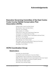
Figure 5-2 Settlement of the Former Soil Remediaton Building. This building<br />
would be rehabilitated <strong>and</strong> exp<strong>and</strong>ed for the proposed WRC. It is<br />
located on fill which has experienced substantial differential settlement<br />
since it was constructed in 1996.
5-22<br />
EIR Recommendations:<br />
MITIGATION MEASURE 5-5<br />
a) Geotechnical studies would be performed for each proposed/renovated site structure<br />
to be located on waste fill that evaluate impacts of l<strong>and</strong>fill settlement on building<br />
performance, as well as additional settlement, if any, caused by new structures, <strong>and</strong><br />
recommendations included in construction plans <strong>and</strong> specifications.<br />
b) Flexible utility connections, if determined to be necessary by the geotechnical<br />
studies, would be used in areas of waste fill to reduce damage to utilities resulting<br />
from differential settlement between buildings <strong>and</strong> the surrounding ground.<br />
c) Settlement of buildings located on waste fill would be addressed in the WCCSL<br />
Post-Closure Plan with monitoring <strong>and</strong> repairs as needed.<br />
Implementation of these measures would reduce settlement impacts to renovation of<br />
existing <strong>and</strong> proposed new structures on the l<strong>and</strong>fill to a less-than-significant level.<br />
IMPACT 5-6. Settlement of the l<strong>and</strong>fill under new refuse <strong>and</strong> cover fill loads could<br />
impact lateral containment structures. This impact is considered potentially<br />
significant.<br />
The proposed WRC site is within about 8 to 10 feet of the soil-attapulgite slurry wall<br />
separating the Class I <strong>and</strong> Class II l<strong>and</strong>fills. An additional barrier wall (Bay Mud <strong>and</strong><br />
soil-cement-bentonite) surrounds the entire WCCSL. Large settlements could cause<br />
ground deformations, which may impact the integrity of the hydraulic barrier properties<br />
of these walls. However, the magnitudes of the expected settlements are not likely to be<br />
large enough to breach the walls.<br />
Control Measures Incorporated by Applicant: None.<br />
EIR Recommendations:<br />
MITIGATION MEASURE 5-6<br />
a) If new fill is placed for renovation of the proposed WRC site, additional geotechnical<br />
studies would be performed by the Applicant to evaluate settlement, slope stability,<br />
<strong>and</strong> potential impacts on the integrity of the soil-attapulgite slurry wall with<br />
recommendations included in construction plans <strong>and</strong> specifications.<br />
b) Monitoring would be performed consistent with the recommendations of<br />
Mitigation Measure 5-6(a) to evaluate the condition of the soil-attapulgite slurry<br />
wall <strong>and</strong> appropriate repairs made as necessary.<br />
09/10/03\WCCSL EIR\Chapter 5.doc\ks
Implementation of these measures would reduce settlement impacts to lateral containment<br />
structures to a less-than-significant level.<br />
5-23<br />
4. Slope Stability under Static <strong>and</strong> Dynamic Conditions<br />
Static stability is a measure of the ability of a natural or made slope <strong>and</strong> its foundation to<br />
withst<strong>and</strong> movements due to imposed loads. Stability is expressed in terms of a “factor-of-safety”<br />
(F.S.). An F.S. is the ratio of strength of the resisting material divided by the imposed loads due to<br />
gravity <strong>and</strong> any external forces, if present. An F.S. of less than one represents a condition where the<br />
imposed loads are greater than the resisting forces, which will result in deformation, while an F.S.<br />
greater than one indicates that the resisting forces are larger than the imposed loads. Typically, a<br />
factor-of-safety of 1.5 or greater is considered to provide adequate margin of safety against a slope<br />
failure in a static condition.<br />
Dynamic stability is the ability of slopes to withst<strong>and</strong> the loads imposed during an<br />
earthquake event. There are two primary impacts that could affect the foundation or cover of the<br />
Class II l<strong>and</strong>fill during a seismic loading condition: (1) deformation of the foundation soils due to<br />
liquefaction, <strong>and</strong> (2) deformation of the foundation materials due to shear failure. Liquefaction was<br />
discussed in Section D2 of this chapter <strong>and</strong> is not a likely mechanism for causing significant<br />
deformation over the majority of the site during earthquake loading. Dynamic slope deformation<br />
due to shear failure has been evaluated by EMCON/OWT. 52 Typically, the result of such an<br />
analysis is an estimate of the amount of deformation a particular slope will undergo as a result of an<br />
earthquake shaking. The level of acceptable deformation is generally considered to be the amount of<br />
deformation that can occur without affecting the cover <strong>and</strong> other environmental control systems.<br />
Global L<strong>and</strong>fill Stability. EMCON/OWT, Inc. (January 2003) performed slope stability<br />
analyses to evaluate the stability of the Class II L<strong>and</strong>fill. 52 This analysis was conducted<br />
pursuant to RWQCB Order No. R2-2001-0066 <strong>and</strong> the peer review of the analysis as<br />
required by the Order is ongoing. The results of this ongoing process with the RWQCB may<br />
further refine the preliminary conclusions summarized below as well as the control measures<br />
that may be required by the RWQCB due to the results of the analysis.<br />
The slope stability analyses were performed using the two-dimensional limit equilibrium<br />
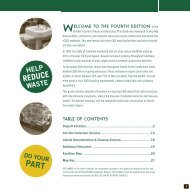
computer program PCSTABL. Three cross sections designated 1-1, 2-2, <strong>and</strong> 3-3 were<br />
used to analyze the global stability that took into account critical locations with respect to<br />
various loading conditions. The locations of the cross sections are shown on Figure 5-3.<br />
The Bay Mud at the southern perimeter of the site (cross section 3-3) appears to have<br />
single drainage (i.e. it can only drain upward into the waste), <strong>and</strong> is therefore likely<br />
partially consolidated, while on the northern <strong>and</strong> western slopes (cross sections 1-1<br />
<strong>and</strong> 2-2) the Bay Mud has double-drainage boundary conditions, resulting in a faster rate<br />
of consolidation. However, filling history suggests fill placement at the northern<br />
boundary was more recent than in the south, <strong>and</strong> the slope configuration on the north <strong>and</strong><br />
west sides is more critical. On the southeastern slope (cross section 3-3), the existing<br />
waste slope is the steepest, the Bay Mud has single-drainage, <strong>and</strong> the time of<br />
09/10/03\WCCSL EIR\Chapter 5.doc\ks
5-24<br />
consolidation is shorter than on the south side. EMCON/OWT concludes the south slope<br />
cross section (1-1) represents the worst critical slope for end-of-filling conditions.<br />
Previous <strong>and</strong> new borings, laboratory data, <strong>and</strong> historic plots of waste profiles were used to<br />
evaluate the degree of consolidation of the Bay Mud, which is related to the strength. The<br />
static slope stability analysis was performed for the end-of-filling conditions corresponding<br />
to the Bay Mud strength in the year 2002 for a maximum waste elevation of 160 feet. The<br />
static slope stability analysis was performed assuming both circular <strong>and</strong> sliding block-type<br />
failure surfaces. For all cases evaluated, the factor of safety is greater than the acceptable<br />
value of 1.5, except at cross-section 3-3 for a circular failure mode. For this analysis, the<br />
factor of safety was 1.46, however, if 3-dimensional effects are considered (the location is in<br />
a valley), EMCON/OWT concludes the factor of safety would be higher than 1.5.<br />
Pseudo-static slope stability analyses were performed to evaluate the yield acceleration of<br />
the failure surfaces during an earthquake. These analyses included a strength increase in Bay<br />
Mud due to the rapid nature of loading during an earthquake. 27 CCR requires that Class II<br />
l<strong>and</strong>fills be designed to withst<strong>and</strong> ground motions from the MCE. An average horizontal<br />
equivalent acceleration (HEA) for the critical failure mass associated with the yield<br />
acceleration was computed for each of seven acceleration-time histories. Associated<br />
displacements were then estimated using a Newmark (1964) type dynamic slope<br />
deformation analysis. The coupled analyses performed by Professor Jonathan Bray, a<br />
consultant to EMCON/OWT, resulted in average seismic displacements of about 1 to 3 feet<br />
for MCEs on the Hayward <strong>and</strong> San Andreas faults. The largest displacements occurred at<br />
cross-section 1-1. However, for cases where degraded material properties were used,<br />
seismic deformations exceeded 5 feet for five of the seven analyzed cases. The largest<br />
computed deformation was 25 feet for the synthetic input earthquake motion simulating the<br />
1906 San Andreas event.<br />
Cover Stability. Stability of the cover under both static <strong>and</strong> dynamic conditions was also<br />
evaluated by EMCON/OWT (January 2003) as related to maintaining slopes. 52 Information<br />
provided by EPA Subtitle D (incorporated by CCR) was used to establish F.S. criteria for<br />
cover design. Slope stability analyses were then performed using an infinite slope method<br />
<strong>and</strong> a peak ground acceleration (PGA) of 0.5g. The maximum required slopes to meet the<br />
F.S. criteria based on the analyses are summarized below:<br />
• The minimum required F.S. for the static condition, without including seepage<br />
forces, is 1.5; analyses show a 4:1 (horizontal:vertical) slope (25 percent) is sufficient<br />
to meet the criteria.<br />
• The minimum required static F.S. for the static condition, including full seepage<br />
forces, is 1.0; analyses show a 5:1 slope (20 percent) is sufficient to meet the criteria.<br />
09/10/03\WCCSL EIR\Chapter 5.doc\ks
N<br />
1"<br />
~<br />
= 560'<br />
1 1<br />
=<br />
5-25<br />
ULTIMATE USES OF THE LANDFILL<br />
Proposed Public<br />
Access Trail<br />
1<br />
2<br />
Closed Class I<br />
Hazardous Waste<br />
Disposal Site<br />
(HWMF)<br />
Area C<br />
Proposed Public<br />
Access Trail<br />
1<br />
2<br />
3<br />
Proposed<br />
Trail Parking<br />
Area<br />
3<br />
Alternate Waste Recycling Center Site<br />
(Area A)<br />
Wet/Dusty<br />
Material Blending<br />
Proposed Dredged Material<br />
& Biosolids Drying Area<br />
Area B<br />
Green Material/Wood<br />
Waste Processing, <strong>and</strong><br />
Soil Reclamation<br />
LEGEND:<br />
Cross Section<br />
Grass Planted Area<br />
L<strong>and</strong>scaped Area<br />
Wildcat Marsh<br />
Proposed Public<br />
Access Trail<br />
Source: WCL, February 2003<br />
Figure 5-3 Location of Slope Stability Cross Sections
5-26<br />
• The maximum allowable cover displacement during an earthquake is one foot;<br />
analyses indicate this criteria can be met using a 7:1 slope (14 percent), or flatter.<br />
Therefore, a proposed topdeck slope of 10:1 (10 percent) or flatter will meet both the static<br />
<strong>and</strong> seismic slope stability criteria. The predicted post-settlement slope of 5 percent also<br />
meets the cover stability <strong>and</strong> drainage criteria.<br />
IMPACT 5-7. The placement of new fill could cause a static slope or cover failure that<br />
could damage the l<strong>and</strong>fill cap <strong>and</strong> environmental control systems. This impact is<br />
considered to be less than significant.<br />
The analyses performed by EMCON/OWT for the cover <strong>and</strong> general l<strong>and</strong>fill indicate the<br />
factors of safety are sufficient to resist sliding of the cover or failure of the l<strong>and</strong>fill in a static<br />
condition. Therefore, impacts associated with the static stability are not significant <strong>and</strong> no<br />
mitigation measures are required.<br />
Control Measures Incorporated by Applicant: None.<br />
EIR Recommendations:<br />
MITIGATION MEASURE 5-7. None required.<br />
IMPACT 5-8. The combination of new fill placement <strong>and</strong> seismic shaking could cause<br />
slope deformations, which could damage the l<strong>and</strong>fill cap <strong>and</strong> environmental control<br />
systems. This impact is considered potentially significant.<br />
EMCON/OWT has concluded the probability of an MCE event occurring on the Hayward<br />
Fault or San Andreas Fault is low, which is in general agreement with the 30-year<br />
probabilities presented in the USGS Group (1999) discussed earlier. The analyses<br />
performed indicate lateral slope displacements on the l<strong>and</strong>fill cover could be on the order of<br />
12 inches, while displacements of the l<strong>and</strong>fill sideslopes could be as much as 25 feet (see<br />
discussion above). 52 This l<strong>and</strong>fill slope deformation would likely result in damage to the<br />
l<strong>and</strong>fill cap <strong>and</strong> GCL, irregular surface <strong>and</strong> related drainage issues, <strong>and</strong> potential distress to<br />
the containment structures (Figure 5-4). As discussed under Impact 5-1, a post-earthquake<br />
maintenance <strong>and</strong> repair plan would be implemented by the Applicant. If the barrier wall is<br />
breached under seismic conditions, an inward hydraulic gradient would be maintained to<br />
control off-site migration of leachate or waste prior to <strong>and</strong> throughout the repair. Due to the<br />
relatively low permeability of the subsurface materials, it is unlikely large-scale, off-site<br />
migration of leachate or waste would occur.<br />
09/10/03\WCCSL EIR\Chapter 5.doc\ks
5-27<br />
Control Measures Incorporated by Applicant:<br />
a) Following an earthquake, an inspection program would be implemented to<br />
evaluate the extent of cracking of the cover materials, damage to LFG collection<br />
system, damage to leachate collection <strong>and</strong> pumping systems, global l<strong>and</strong>fill<br />
sliding, <strong>and</strong> cracking of the barrier wall. Appropriate repairs would be made<br />
pursuant to RWQCB Order No. R2-2002-0066.<br />
b) Under the seismic scenarios where the barrier wall is breached, an inward<br />
hydraulic gradient would be maintained prior to <strong>and</strong> throughout the repair (see<br />
Control Measure 5.1(c)).<br />
c) A slope remediation study would be performed, or a long-term slope maintenance<br />
program would be developed to address the consequence <strong>and</strong> possible repairs<br />
resulting from large seismically-induced permanent slope displacements.<br />
d) As recommended in the EMCON/OWT, Inc. slope stability report, a probabilistic<br />
analysis of the permanent displacements would be performed to be used in<br />
developing a detailed earthquake response plan. The response plan would<br />
provide details on procedures to be followed for inspection of the site following<br />
major earthquakes, <strong>and</strong> on the slope maintenance requirement that may be<br />
triggered by significant displacements.<br />
EIR Recommendations:<br />
MITIGATION MEASURE 5-8:<br />
a) A plan for inspection <strong>and</strong> as-needed repair of the GCL following an earthquake<br />
would be added to the Postclosure Plan.<br />
Implementation of this mitigation measure would reduce impacts associated with slope<br />
deformations to a less-than-significant level.<br />
IMPACT 5-9. Slope deformations or slope failure at the proposed WRC site could<br />
impact the soil-attapulgite slurry wall. This impact is considered potentially<br />
significant.<br />
The stability of the fill pad at the former Soil Remediation Building <strong>and</strong> related effects on<br />
the soil-attapulgite slurry wall separating the Class I <strong>and</strong> Class II L<strong>and</strong>fills were<br />
evaluated by Woodward-Clyde Consultants in 1995. 90 The building design uses geogrid<br />
reinforcement within the fill pad <strong>and</strong> a downslope berm. The expected lateral<br />
deformation of the pad during a seismic event would be limited to 3 to 4 inches. This<br />
level of displacement is not likely to significantly impact the 5-foot-wide slurry wall.<br />
09/10/03\WCCSL EIR\Chapter 5.doc\ks
5-28<br />
Class II L<strong>and</strong>fill<br />
Figure 5-4 L<strong>and</strong>fill Seismic Displacements. The Southern area of the Class II<br />
l<strong>and</strong>fill shown here is less stable than other areas under certain<br />
seismic conditions. A detailed earthquake response plan will be<br />
developed by the Applicant (Control Measure 5.7 (d))
However, localized repair of the soil-attapulgite slurry wall (<strong>and</strong> the cover system) may be<br />
required.<br />
Control Measures Incorporated by Applicant:<br />
a) The inspection, monitoring <strong>and</strong> repair plans outlined in the Post-Closure<br />
Maintenance Plan would be followed.<br />
5-29<br />
b) Following a significant earthquake (magnitude 6.5 or greater) the site would be<br />
inspected to evaluate the performance of the environmental control systems<br />
related to the Class I L<strong>and</strong>fill. Slurry wall deformations in excess of 1 foot would<br />
require notification to the State Department of Toxic Substances Control (DTSC)<br />
<strong>and</strong> RWQCB within 14 days <strong>and</strong> repairs made pursuant to their recommendations.<br />
EIR Recommendations:<br />
MITIGATION MEASURE 5-9:<br />
a) If new fill will be placed for renovation of the proposed WRC site, additional<br />
studies would be performed to evaluate potential settlement, slope stability, <strong>and</strong><br />
movement of the soil-attapulgite slurry wall <strong>and</strong> recommendations would be<br />
incorporated into construction plans <strong>and</strong> specifications (see Mitigation<br />
Measure 5.6(a)).<br />
Implementation of these measures would reduce seismic shaking impacts to a less-thansignificant<br />
level.<br />
5. Seismic Shaking of Building Structures <strong>and</strong> Associated Improvements<br />
IMPACT 5-10. Ground shaking during an earthquake could affect building structures<br />
<strong>and</strong> associated improvements. This impact is considered potentially significant.<br />
An earthquake on a nearby fault would cause ground shaking at the l<strong>and</strong>fill site. If new<br />
structures are not designed to resist earthquake ground motions, damage could be sustained.<br />
Ground shaking with respect to liquefaction <strong>and</strong> slope stability were discussed in previous<br />
sections.<br />
Control Measures Incorporated by Applicant:<br />
a) New buildings would be designed to meet the 1997 Uniform Building Code (UBC)<br />
Seismic Zone Factor 4 st<strong>and</strong>ards, <strong>and</strong> constructed in accordance with all applicable<br />
building codes <strong>and</strong> regulations.<br />
09/10/03\WCCSL EIR\Chapter 5.doc\ks
5-30<br />
EIR Recommendations:<br />
MITIGATION MEASURE 5-10:<br />
a) To ensure proper structural design, a geotechnical report would be prepared for<br />
all new buildings to be located on waste fill with recommendations incorporated<br />
into construction plans <strong>and</strong> specifications (see Mitigation Measure 5-5(a)). The<br />
geotechnical report would discuss the potential for differential ground surface<br />
settlement <strong>and</strong> the need for flexible utility connections (see Mitigation<br />
Measure 5.5(b)).<br />
Implementation of these measures would reduce seismic shaking impacts to buildings<br />
<strong>and</strong> site improvements to a less-than-significant level.<br />
6. Cover Protection<br />
IMPACT 5-11. The construction <strong>and</strong> operation of new buildings <strong>and</strong> facilities, as well<br />
as construction of the cap itself, could cause damage to the l<strong>and</strong>fill cover (cap). This<br />
impact is considered to be less than significant.<br />
The cover, <strong>and</strong> in particular the GCL, must not sustain damage during construction or postclosure<br />
activities to allow it to function properly. The GCL could be damaged during<br />
placement due to puncture by underlying materials or the cover soil, or by ripping. The<br />
l<strong>and</strong>fill cap would be overlain by an additional 3 feet of protective soil in post-closure<br />
operations areas. At the former Soil Remediation Building, a regulatory-compliant l<strong>and</strong>fill<br />
cover system was installed before construction of the building. A 60-mil high density<br />
polyethylene (HDPE) (plastic) liner provides a barrier between the soil underlying the<br />
building foundation <strong>and</strong> the l<strong>and</strong>fill cap.<br />
Control Measures Incorporated by Applicant:<br />
a) During construction, the subgrade would be prepared properly to create a smooth<br />
surface <strong>and</strong> proper construction <strong>and</strong> quality assurance monitoring would be<br />
conducted consistent with the requirements of the Postclosure Plan.<br />
b) If the cover (including the GCL) is damaged during construction or post-closure<br />
activities, it would be repaired or replaced.<br />
Implementation of these measures would reduce impacts to the l<strong>and</strong>fill cap to less-thansignificant<br />
levels. Other control measures to assure the integrity of the final l<strong>and</strong>fill cap are<br />
discussed in Chapter 6, Water Resources (Control Measures 6-2 (a, b, c).<br />
09/10/03\WCCSL EIR\Chapter 5.doc\ks
5-31<br />
EIR Recommendations:<br />
MITIGATION MEASURE 5-11: None required.<br />
7. Impacts of Mitigation Measures<br />
None of the mitigation measures discussed above will have any significant adverse<br />
impacts.<br />
E. CUMULATIVE IMPACTS<br />
The proposed Project would not have any geologic, soil, or seismic impacts that cannot<br />
be mitigated to less-than-significant levels. The Applicant must comply with State requirements<br />
as well as the recommendations in this EIR to ensure the geologic compatibility of the proposed<br />
Project <strong>and</strong> the WCCSL site. Similarly, all future development projects discussed in Chapter 4,<br />
Section A3(b) would be subject to the requirements of the CEQA <strong>and</strong> State <strong>and</strong> local agency<br />
requirements in regard to the identification <strong>and</strong> protection against geologic, soil, <strong>and</strong> seismic<br />
hazards. For most projects, soil studies are required through the building permit process in order<br />
to mitigate impacts from soil problems such as liquefaction, unstable soils, <strong>and</strong> soils with a large<br />
degree of shrink/swell. Mitigation measures for potential impacts from such problem soils<br />
include proper foundation construction <strong>and</strong> soil anchors. All buildings <strong>and</strong> other facilities must<br />
be constructed to meet specified earthquake requirements contained in the Uniform Building<br />
Code. As a result, there are no cumulative geologic, soil, or seismic impacts that would result<br />
from the proposed Project <strong>and</strong> other cumulative projects in the area.<br />
09/10/03\WCCSL EIR\Chapter 5.doc\ks