Electric Signature Analysis - AREVA NP Inc.
Electric Signature Analysis - AREVA NP Inc.
Electric Signature Analysis - AREVA NP Inc.

Create successful ePaper yourself
Turn your PDF publications into a flip-book with our unique Google optimized e-Paper software.
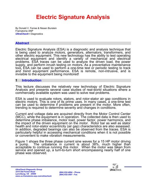
<strong>Electric</strong> <strong>Signature</strong> <strong>Analysis</strong><br />
By Donald V. Ferree & Nissen Burstein<br />
Framatome A<strong>NP</strong><br />
UltraCheck® Diagnostics<br />
Abstract<br />
<strong>Electric</strong> <strong>Signature</strong> <strong>Analysis</strong> (ESA) is a diagnostic and analysis technique that<br />
is being used to analyze motors, generators, alternators, transformers, and<br />
other electric equipment. This new technology has the ability to test operating<br />
electrical equipment and identify a variety of mechanical and electrical<br />
problems. ESA traces can be used to analyze the driven load, the power<br />
supply, and perform inrush testing on motors. As a preventative maintenance<br />
tool, ESA can be used to perform a one-time test or periodic testing to track<br />
and trend equipment performance. ESA is remote, non-intrusive, and is<br />
invisible to the equipment being monitored!<br />
1 Introduction<br />
This lecture discusses the relatively new technology of <strong>Electric</strong> <strong>Signature</strong><br />
<strong>Analysis</strong> and presents several case studies of real-world situations where a<br />
commercially available system was used to solve real problems.<br />
ESA is used to evaluate rotors, stators, and rotor-stator air gap conditions in<br />
electric motors. This is one of its prime uses. In many cases, a one-time test<br />
can be used to determine if problems are present in the motor. More often,<br />
trending is required to determine severity and changes in conditions.<br />
Current and voltage data are acquired directly from the Motor Control Center<br />
(MCC), while the equipment is in operation. The collected data is then used to<br />
determine phase imbalance, motor load, power factor, power harmonics, and<br />
the impact of the driven equipment on the motor. Rotor bar as well as stator<br />
health and rotor-stator eccentricity (air gap) characteristics are also assessed.<br />
In addition, degraded bearings can also be observed from the traces. ESA is<br />
particularly helpful in accessing mechanical conditions when it is not possible<br />
or convenient to make vibration measurements.<br />
Figure 1 shows the three phase current sine waves for a 15 HP motor driving<br />
a pump. The unbalance in current is about 38%, much higher than<br />
acceptable to continue running this motor. When the motor was taken from<br />
service and opened up, a turn-to-turn short encompassing nearly half of one<br />
phase was observed.<br />
UltraCheck Diagnostic Group<br />
3315 Old Forest Road<br />
Lynchburg, VA 24506<br />
www.us.framatome-anp.com/ultracheck<br />
(804) 832-4094 – Phone<br />
(804) 832-3507 - Fax
Figure1. Three phase currents of 15 Hp motor with a severe turn-to-turn short.<br />
Figure 2 shows the current spectrum of one phase of a motor driving a<br />
compressor. The rotor has broken rotor bars as evidenced by the amplitude<br />
of the pole passing sidebands around the line frequency peak at 59.97 Hz.<br />
Figure 2. Current spectrum of 300 Hp motor showing pole passing sidebands to line frequency.<br />
UltraCheck Diagnostic Group<br />
3315 Old Forest Road<br />
Lynchburg, VA 24506<br />
www.us.framatome-anp.com/ultracheck<br />
(804) 832-4094 – Phone<br />
(804) 832-3507 - Fax
Figure 3 shows the peaks evident in the current spectrum of a motor that has<br />
a broken bearing. The peaks highlighted by colored cursors are a result of<br />
the modulation of the current draw of the motor by the broken bearing.<br />
Figure 3. Current spectrum of a 200 Hp motor showing a bearing damage pattern.<br />
For DC motors and motors with separate power supplies, such as variable<br />
frequency drives, ESA monitors the power supply and can point out problems<br />
in it.<br />
Figure 4 shows the armature current spectrum for a DC motor. The large<br />
peak at 360 Hz indicates the DC drive is full-wave-rectified. The large peaks<br />
at 120 and 240 Hz indicate problems in the control circuitry of the DC drive.<br />
Figure 4. Current spectrum of DC motor showing drive characteristics.<br />
UltraCheck Diagnostic Group<br />
3315 Old Forest Road<br />
Lynchburg, VA 24506<br />
www.us.framatome-anp.com/ultracheck<br />
(804) 832-4094 – Phone<br />
(804) 832-3507 - Fax
2 Trending of Motor Data<br />
ESA becomes even more useful, however, for trending motor indications;<br />
because, in some cases, a motor’s base-line signature may not be known.<br />
The ideal information a predictive/preventive maintenance engineer needs to<br />
know is, “How long until I need to replace or repair this motor?”<br />
Rarely can a one-time test provide this data. However, trending will give this<br />
input by providing an indication of how quickly a motor condition is changing.<br />
For example, if an indication of rotor degradation appears, it may not be clear<br />
from one test how rapidly the rotor circuit is degrading. Testing over several<br />
weeks or months will confirm if the rotor is stable and not changing. The<br />
number of starts and stops that a motor experiences is very important<br />
regarding rotor change. A motor with a high on-off duty cycle is much more<br />
likely to show rapidly increasing rotor degradation than a motor that runs<br />
constantly. These types of operating conditions can be factored into the<br />
trending data to provide a much clearer indication of motor health.<br />
Figure 5 shows the current spectrum of a 1750 Hp motor that has “soft foot”.<br />
The “soft foot” shows up as static eccentricity, or air gap variation. The peaks<br />
highlighted by the colored cursors are the rotor bar passing peaks indicative<br />
of static eccentricity. This condition can be determined with a single test.<br />
Degrading static eccentricity will be seen as the peaks grow in amplitude.<br />
Figure 5. Current spectrum of 1750 Hp motor showing rotor bar passing pattern.<br />
UltraCheck Diagnostic Group<br />
3315 Old Forest Road<br />
Lynchburg, VA 24506<br />
www.us.framatome-anp.com/ultracheck<br />
(804) 832-4094 – Phone<br />
(804) 832-3507 - Fax
3 Monitoring the Driven Load<br />
In some cases, it is the driven load that is more important to the<br />
Predictive/Preventative Maintenance professional than is the motor. In this<br />
case, ESA is used to differentiate between the motor and load characteristics.<br />
This has been successfully demonstrated on pulverizers at coal-fired power<br />
plants, on motor-operated valves, pump motors, and in other areas.<br />
Figure 6 shows the demodulated current spectrum of a motor driven by a<br />
variable frequency drive. The motor drives a belt that drives a fan. The<br />
peaks in the spectrum are the belt passing peak at 5.64 Hz, the second<br />
harmonic of belt passing at 11.24 Hz, motor running speed at 22.05 Hz and<br />
fan blade passing at 41.44 Hz. The VFD was running at about 45 Hz and the<br />
motor has four poles.<br />
Figure 6. Demodulated current spectrum showing belt passing, motor running speed and blade passing.<br />
UltraCheck Diagnostic Group<br />
3315 Old Forest Road<br />
Lynchburg, VA 24506<br />
www.us.framatome-anp.com/ultracheck<br />
(804) 832-4094 – Phone<br />
(804) 832-3507 - Fax
Figure 7 shows the demodulated spectrum of a DC motor driving a gearbox.<br />
The peaks at 8.62 Hz and multiples are from one of the shafts in the gear<br />
box. Sidebands are evident around the peak at 8.62 Hz; these come from<br />
gear meshing modulation on the shaft. The numerous peaks at the lower end<br />
of the spectrum come from the gearbox shafts and from the hunting tooth<br />
frequencies in the gear meshing.<br />
Figure 7. Demodulated current spectrum of DC motor showing gearbox features.<br />
4 Monitoring the Power Supply<br />
The power supply, a variable frequency drive or the power coming in on the<br />
bus, are all-important components of the load-driving system. In some cases,<br />
the power supply contributes to the problems being experienced with the<br />
motor. ESA is used to diagnose problems in the power supply and can<br />
provide insight into the root cause of motor problems that can be obtained in<br />
no other way.<br />
Figure 8 shows the voltage supplied by a VFD when the VFD is being<br />
overdriven by high voltage. Note first the peak at 52 Hz, the drive output line<br />
frequency. Then note the large number of peaks near 2975 Hz which arise<br />
from the chopping frequency of the VFD. In this case, the motor being<br />
powered by this VFD was being destroyed because of the high frequency<br />
ripple riding on the VFD line frequency.<br />
UltraCheck Diagnostic Group<br />
3315 Old Forest Road<br />
Lynchburg, VA 24506<br />
www.us.framatome-anp.com/ultracheck<br />
(804) 832-4094 – Phone<br />
(804) 832-3507 - Fax
Figure 8. Current spectrum of VFD showing line frequency and chopping frequency peaks.<br />
5 Inrush Testing<br />
ESA is also useful for inrush testing. Inrush testing can provide data on the<br />
motor and the power circuit, including breakers. This information can be used<br />
to help diagnose motor or power supply problems that can be used to<br />
improve motor performance. In one case, breaker bounce was detected and<br />
enabled the plant maintenance engineer to understand why the plant<br />
struggled to bring the motor on line.<br />
Figure 9 shows the inrush for a 9,000 Hp motor attached to a pump. Note<br />
that is takes over 11 seconds for this motor to come to its normal operating<br />
speed. Most motors achieve standard operating speed in a second or less,<br />
but this 9,000 Hp motor/pump represents a very large mass to bring up to<br />
speed.<br />
Figure 9. Inrush current of 9,000 Hp motor and pump requiring almost 11 seconds to start.<br />
UltraCheck Diagnostic Group<br />
3315 Old Forest Road<br />
Lynchburg, VA 24506<br />
www.us.framatome-anp.com/ultracheck<br />
(804) 832-4094 – Phone<br />
(804) 832-3507 - Fax
6 Conclusions<br />
ESA is a useful tool to monitor and diagnose the power supply, the<br />
motor and the driven load. ESA can be used to perform a one-time test<br />
or periodic testing to track and trend equipment performance. ESA is<br />
remote, non-intrusive, and is invisible to the equipment being<br />
monitored. Data acquisition takes less than two minutes per motor.<br />
LAN-based, continuous monitoring of motors is readily accomplished.<br />
7 References<br />
[1] Brown, E. David, “Current <strong>Signature</strong> <strong>Analysis</strong> at the Everett Plant of Boeing<br />
Commercial Airplane Group,” P/PM TECHNOLOGY, August – 1998.<br />
[2] Lang, George Fox, “Of Cages, Induction, Deduction, Bars, Vars and Squirrels,”<br />
SOUND AND VIBRATION, December - 1994.<br />
[3] Burstein, Nissen M. and Ferree, Donald V., “Monitoring <strong>Electric</strong> Motor<br />
Condition Using Current <strong>Signature</strong> <strong>Analysis</strong>: Case Histories and Success Stories,”<br />
International Maintenance Technology and Information Symposium, November -<br />
1996.<br />
[4] Lanier, Chris, “What to look for in inverter-duty motors”, PLANT<br />
ENGINEERING, December - 1998.<br />
[5] Phipps, Clarence A., (1999) Variable Speed Drive Fundamentals, The Fairmont<br />
Press, Lilburn, GA.<br />
[6] Nailen, Richard L., (1996) Managing Motors, Second Edition, Barks<br />
Publications, <strong>Inc</strong>., Chicago, IL.<br />
[7] Patrick, Dale R. and Fardo, Stephen, W., (1996) Rotating <strong>Electric</strong>al Machines &<br />
Power Systems, The Fairmont Press, Lilburn, GA.<br />
[8] Berry, James E., (1992) “Comparison of Motor Current <strong>Analysis</strong> and Vibration<br />
<strong>Analysis</strong> in Detecting Rotor Bar and Air Gap Eccentricity Problems in Induction<br />
Motors,” Technical Associates of Charlotte, <strong>Inc</strong>., Charlotte, NC.<br />
[9] Simoncic, David A. and Berry, James E., (1996) “DC Motor and Control<br />
Problem Identification Using Vibration <strong>Analysis</strong>,” Technical Associates of Charlotte,<br />
<strong>Inc</strong>., Charlotte, NC.<br />
[10] Mazur, Glen A., (1999) Power Measurement and Trouble Shooting, American<br />
Technical Publishers, <strong>Inc</strong>., Homewood, IL.<br />
UltraCheck Diagnostic Group<br />
3315 Old Forest Road<br />
Lynchburg, VA 24506<br />
www.us.framatome-anp.com/ultracheck<br />
(804) 832-4094 – Phone<br />
(804) 832-3507 - Fax