Development of an Axial-Flux Permanent Magnet (AFPM ... - Ijcns.com
Development of an Axial-Flux Permanent Magnet (AFPM ... - Ijcns.com
Development of an Axial-Flux Permanent Magnet (AFPM ... - Ijcns.com

You also want an ePaper? Increase the reach of your titles
YUMPU automatically turns print PDFs into web optimized ePapers that Google loves.
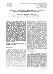
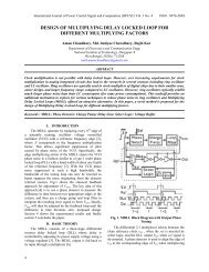
Neodymium Iron Boron (NdFeB) perm<strong>an</strong>ent<br />
magnets are used for this machine <strong>an</strong>d are fixed in<br />
slots made on rotor core (stampings) by using<br />
adhesive. The rotor core is placed in between two<br />
plates to give more strength. The whole structure is<br />
finally mounted on alternator shaft. The rotor body<br />
is then placed between two stator plates. The GA<br />
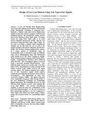
drawing <strong>an</strong>d internal rotor views are shown below:<br />
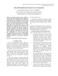
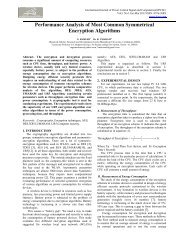
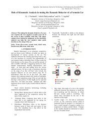
After on bench testing <strong>of</strong> alternator, it was<br />
integrated with flywheel <strong>of</strong> variable speed prime<br />
mover (IC engine) in acoustic container with<br />
suitable <strong>an</strong>ti vibration mountings on a base frame to<br />
make it as a dedicated <strong>com</strong>pact power source.<br />
Integrated view <strong>of</strong> mobile power source is as shown<br />
below:<br />
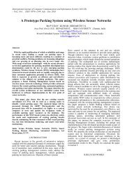
Fig. 7 Rotor GA Drawing<br />
Fig.10 Integrated view <strong>of</strong> Compact Mobile Power Source<br />
7.1 Perform<strong>an</strong>ce Evaluation <strong>an</strong>d Testing:<br />
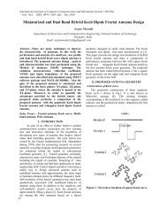
Fig.8 Internal view <strong>of</strong> Rotor<br />
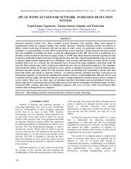
VII. SYSTEM INTEGRATION<br />
After integration <strong>of</strong> <strong>AFPM</strong> Alternator, it was<br />
tested under simulated conditions to study the<br />
characteristic <strong>an</strong>d behavior <strong>of</strong> alternator in terms <strong>of</strong><br />
electrical perform<strong>an</strong>ce parameters such as tr<strong>an</strong>sient<br />
voltage dip, rise <strong>an</strong>d its recovery from no load to full<br />
load <strong>an</strong>d vise versa. Temp rise during endur<strong>an</strong>ce<br />
(continuous run <strong>of</strong> 7 to 8 hrs) <strong>of</strong> the machine was<br />
also noted at air intake <strong>an</strong>d hot air outlet point <strong>an</strong>d it<br />
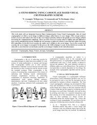
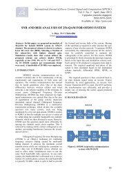
was less th<strong>an</strong> 65°C. This integrated machine inside<br />
<strong>an</strong> acoustic container has been tested at various<br />
speeds from 800 to 2300 rpm <strong>an</strong>d corresponding<br />
alternator output voltage is also increased from 148<br />
to 401V.<br />
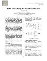
Stator body is housed in a back iron (yoke) <strong>an</strong>d<br />
this assembly is mounted on a shaft. Rotor is also<br />
positioned on the same shaft in between two stators.<br />
The <strong>com</strong>plete assembly in a single package called as<br />
<strong>AFPM</strong> alternator is integrated with induction motor<br />
with variable speed drive for system evaluation<br />
under simulated load conditions.<br />
450<br />
400<br />
350<br />
300<br />
250<br />
Voltage<br />
200<br />
150<br />
100<br />
Speed vs o/p Voltage<br />
50<br />
0<br />
VSD<br />
804<br />
918<br />
1010<br />
1100<br />
1200<br />
1317<br />
1419<br />
1504<br />
1618<br />
1704<br />
Speed R.P.M<br />
1808<br />
1900<br />
2032<br />
2103<br />
2208<br />
2308<br />
Fig. 11 Speed v/s output voltage curve<br />
Coupling<br />
Induction motor<br />
<strong>AFPM</strong><br />
Alt.<br />
Fig.9 Simulation test set up<br />
This machine has undergone rigorous testing for<br />
resistive <strong>an</strong>d inductive load (0.8 power factor) for<br />
verification <strong>of</strong> actual load conditions <strong>an</strong>d found<br />
efficiency <strong>of</strong> 94%, which shows excellent <strong>an</strong>d<br />
satisfactory perform<strong>an</strong>ce results <strong>of</strong> the machine. The<br />
waveform given below shows the smooth sinusoidal<br />
voltage output.