Design and Analysis of an Automotive Vacuum Suspended Power ...
Design and Analysis of an Automotive Vacuum Suspended Power ...
Design and Analysis of an Automotive Vacuum Suspended Power ...

You also want an ePaper? Increase the reach of your titles
YUMPU automatically turns print PDFs into web optimized ePapers that Google loves.
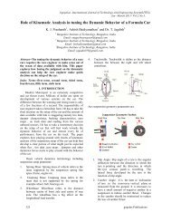
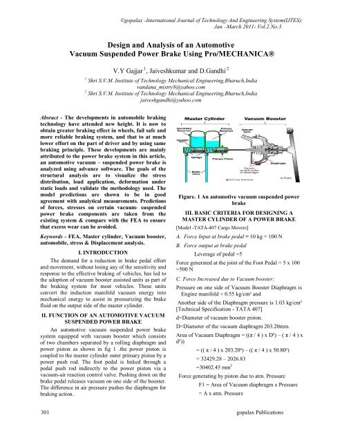
©gopalax -International Journal <strong>of</strong> Technology And Engineering System(IJTES):J<strong>an</strong> –March 2011- Vol.2.No.3.<strong>Design</strong> <strong><strong>an</strong>d</strong> <strong>Analysis</strong> <strong>of</strong> <strong>an</strong> <strong>Automotive</strong><strong>Vacuum</strong> <strong>Suspended</strong> <strong>Power</strong> Brake Using Pro/MECHANICA®V.Y Gajjar 1 , Jaiveshkumar <strong><strong>an</strong>d</strong> D.G<strong><strong>an</strong>d</strong>hi 21 Shri S.V.M. Institute <strong>of</strong> Technology Mech<strong>an</strong>ical Engineering,Bharuch,Indiav<strong><strong>an</strong>d</strong><strong>an</strong>a_mistry8@yahoo.com2 Shri S.V.M. Institute <strong>of</strong> Technology Mech<strong>an</strong>ical Engineering,Bharuch,Indiajaiveshg<strong><strong>an</strong>d</strong>hi@yahoo.comAbsract - The developments in automobile brakingtechnology have attended new height. It is now toobtain greater braking effect in wheels, fail safe <strong><strong>an</strong>d</strong>more reliable braking system, <strong><strong>an</strong>d</strong> that to at muchlower effort on the part <strong>of</strong> driver <strong><strong>an</strong>d</strong> by using samebraking principle. These developments are mainlyattributed to the power brake system in this article,<strong>an</strong> automotive vacuum – suspended power brake is<strong>an</strong>alyzed using adv<strong>an</strong>ce s<strong>of</strong>tware. The goals <strong>of</strong> thestructural <strong>an</strong>alysis are to visualize the stressdistribution, load application, deformation understatic loads <strong><strong>an</strong>d</strong> validate the methodology used. Themodel predictions are shown to be in goodagreement with <strong>an</strong>alytical measurements. Predictions<strong>of</strong> forces, stresses on certain vacuum- suspendedpower brake components are taken from theexisting system & compare with the FEA to ensurethat excess wear c<strong>an</strong> be avoided.Keywords - FEA, Master cylinder, <strong>Vacuum</strong> booster,automobile, stress & Displacement <strong>an</strong>alysis.I. INTRODUCTIONThe dem<strong><strong>an</strong>d</strong> for a reduction in brake pedal effort<strong><strong>an</strong>d</strong> movement, without losing <strong>an</strong>y <strong>of</strong> the sensitivity <strong><strong>an</strong>d</strong>response to the effective braking <strong>of</strong> vehicles, has led tothe adoption <strong>of</strong> vacuum booster assisted units as part <strong>of</strong>the braking system for most vehicles. These unitsconvert the induction m<strong>an</strong>ifold vacuum energy intomech<strong>an</strong>ical energy to assist in pressurizing the brakefluid on the output side <strong>of</strong> the master cylinder.II. FUNCTION OF AN AUTOMOTIVE VACUUMSUSPENDED POWER BRAKEAn automotive vacuum suspended power brakesystem equipped with vacuum booster which consists<strong>of</strong> two chambers separated by a rolling diaphragm <strong><strong>an</strong>d</strong>power piston as shown in fig 1 .the power piston iscoupled to the master cylinder outer primary piston by apower push rod. The foot pedal is linked through apedal push rod indirectly to the power piston via avacuum-air reaction control valve. Pushing down on thebrake pedal releases vacuum on one side <strong>of</strong> the booster.The difference in air pressure pushes the diaphragm forbraking action.Figure. 1 An automotive vacuum suspended powerbrakeIII. BASIC CRITERIA FOR DESIGNING AMASTER CYLINDER OF A POWER BRAKE[Model -TATA-407 Cargo Movers]A. Force Input at brake pedal = 10 kg = 100 NB. Force output at brake pedalLeverage <strong>of</strong> pedal =5Force generated at the joint <strong>of</strong> the Foot Pedal = 5 x 100=500 NC. Force Increased due to <strong>Vacuum</strong> booster:Pressure on one side <strong>of</strong> <strong>Vacuum</strong> Booster Diaphragm isEngine m<strong>an</strong>ifold = 0.55 kg/cm² <strong><strong>an</strong>d</strong>Another side <strong>of</strong> the Diaphragm pressure is 1.03 kg/cm²[Technical Specification - TATA 407]d=Diameter <strong>of</strong> vacuum booster piston.D=Diameter <strong>of</strong> the vacuum diaphragm 203.20mm.Area <strong>of</strong> <strong>Vacuum</strong> Diaphragm = ((π / 4 ) x D²) – ( π / 4 ) xd²))= (( π / 4 ) x 203.20²) – (( π / 4 ) x 50.80²)= 32429.28 – 2026.83=30402.45 mm 2Force generating by piston due to atm. PressureF1 = Area <strong>of</strong> <strong>Vacuum</strong> diaphragm x Pressure= A x atm. Pressure301 gopalax Publications
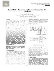
= 30402.45 x atm. PressureIV. METHODOLOGY USED= 30402.45 x 0.101315The modeling <strong><strong>an</strong>d</strong> stress <strong>an</strong>alysis <strong>of</strong> the vacuumsuspended power brake has been done in= 3080.22 NPro/ENGINEER Wildfire 3.0 <strong><strong>an</strong>d</strong> Pro/MECHANICAForce generating by piston due to vacuum Pressure respectively, taking various constraints <strong><strong>an</strong>d</strong> boundaryF2 = Area <strong>of</strong> <strong>Vacuum</strong> diaphragm x vacuum pressure conditions. The necessary design modifications havealso been made to rectify the problems being faced by= A x vacuum pressurethe designer.= 30402.45 x vacuum. Pressure= 30402.45 x 0.055= 1672.13 NIncrease in the Force due to <strong>Vacuum</strong>:-= F1- F2= 3080.22 – 1672.13= 1408.09 NTotal force acting on the Piston <strong>of</strong> the Master Cylinder = 500 +1408.09 = 1908.09 N = 2002N=D. <strong>Design</strong> <strong>of</strong> the Master Cylinder:-Master cylinder oil pressure calculation.Specification - TATA 407 ][TechnicalMaterial <strong>of</strong> the Master Cylinder is Aluminum Alloys(cast).According to IS designation material identify as a IS4225 or BS LM16.σ u = 173 to 205 N/mm 2Take the allowable tensile stress for aluminum cylinderis 0.4 x σ u = 0.4 x 173σ t = 44.98 N/mm 2By Considering the surface finish factor 0.9 <strong><strong>an</strong>d</strong> Factor<strong>of</strong> safety 2.0So Tensile Stress for Master Cylinder <strong>Design</strong>Calculationσ t = 20.24 N/mm 2Take, Master Cylinder inside Diameter.di = 25 mm [Technical Specification - TATA 407 ]Master Cylinder Force produced by <strong>Vacuum</strong> Booster W= 2002 N.Pressure developed in the Master CylinderW = [(π/4) di² x p]p = 4.08 N / mm 2For safe side take the inside cylinder pressure is 10 to20% <strong>of</strong> generated pressure.So take the Inside cylinder pressure is p = 4.08 x 1.14 =4.66 N/mm2 (Factor <strong>of</strong> safety)Figure.2 Problem solving approachA. ConstraintsThere were various constraints or restrictions thatwere imposed by the designer. Material: - for master cylinder"LM16"havingDensity 2.79355e-09 tonne / mm^3, Young’sModulus 73084.4 N / mm^2, Poisson’s Ratio0.33, Ultimate tensile stress173 to 205 N/mm 2Type <strong>of</strong> power brake: - Type c<strong>an</strong>not be otherth<strong>an</strong> <strong>an</strong> automotive vacuum suspended powerbrake <strong>of</strong> TATA 407 Model. Internal Pressure: - There is uniform internalpressure acting in the power brake mastercylinder system at 4.66 N/mm 2 .V. STRESS ANALYSIS FOR AN AUTOMOTIVEVACUUM SUSPENDED POWER BRAKEThe following steps are used for problem solving: -A. Model GenerationProper modeling <strong>of</strong> the parts is very import<strong>an</strong>tfor getting accurate results <strong>of</strong> <strong>an</strong>alysis. Creating theparts <strong><strong>an</strong>d</strong> its dimensioning scheme are import<strong>an</strong>tsteps. The components <strong>of</strong> the shock absorber weremodeled in the part mode <strong>of</strong> Pro/ENGINEERWildfire 3.0. An automotive vacuum suspendedpower brake consists <strong>of</strong> the following part. Master cylinder Master cylinder pistongopalax Publications 302
<strong>Vacuum</strong> boosterThese parts <strong>of</strong> <strong>an</strong> automotive vacuum suspendedpower brake are shown in following figures.B. Assembly <strong>of</strong> <strong>an</strong> automobile vacuum suspended powerbrakeThe assembly <strong>of</strong> all the components <strong>of</strong> <strong>an</strong>automotive vacuum suspended power brake was donein the assembly mode <strong>of</strong> Pro/ENGINEER Wildfire 3.0.The placement (or assembly) constraints were used torigidly bind the components <strong>of</strong> power brake to theirrespective positions in the assembly.The Assembly <strong>of</strong> a <strong>Vacuum</strong> <strong>Suspended</strong> <strong>Power</strong>Brake System is shown in following figure.Figure. 6 Explored View <strong>of</strong> the master CylinderThe Assembly <strong>of</strong> the <strong>Vacuum</strong> Booster is shown infollowing figures.Figure. 7 Assembly <strong>of</strong> the vacuum booster.Figure3 Assembly <strong>of</strong> the vacuum suspended powerbrake system.Figure. 8 Exploded view <strong>of</strong> the vacuum.boosterFigure 4 Cut section view <strong>of</strong> vacuumsuspended power brake system.The Assembly <strong>of</strong> the Master Cylinder –Piston isshown in following figure.Figure 5 Assembly <strong>of</strong> the master cylinder.C. Static Structural <strong>Analysis</strong>With the wide spread adoption <strong>of</strong> CAE approach todesign, Finite Element (FE) <strong>an</strong>alysis became integratedwith the design <strong><strong>an</strong>d</strong> <strong>an</strong>alysis procedure. Structural <strong>an</strong>alysisis used to <strong>an</strong>alyze parts <strong><strong>an</strong>d</strong> assemblies to find :- Maximum stresses Deformed Shapes (Deformation)The <strong>an</strong>alysis <strong>of</strong> a structure during its designprocess is accomplished by the solution <strong>of</strong> the partialdifferential equations that describes the given model.D. Steps involved in carrying out <strong>an</strong>alysis usingPro/MECHANICAPro/MECHANICA is a computer aidedengineering tool that allows us to simulate the physicalbehavior <strong>of</strong> a part or assembly, to underst<strong><strong>an</strong>d</strong> <strong><strong>an</strong>d</strong>improve mech<strong>an</strong>ical perform<strong>an</strong>ce <strong>of</strong> a design. It enablesus to <strong>an</strong>alyze <strong><strong>an</strong>d</strong> optimize the design for structural,thermal <strong><strong>an</strong>d</strong> dynamic requirements.The steps involved in carrying out <strong>an</strong>alysis usingPro/MECHANICA are given below:-303 gopalax Publications
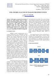
3D part modelingMake three dimensional model <strong>of</strong> <strong>an</strong>automotive vacuum suspended power brakeusing Part <strong><strong>an</strong>d</strong> Assembly mode <strong>of</strong>Pro/ENGINEER Wildfire 3.0. Define the FEA modelAt least there are three basic elements to bespecified to define a FEA model, i.e., material,loads <strong><strong>an</strong>d</strong> constraints. Define material properties, loads <strong><strong>an</strong>d</strong>constraintsMaterial assign to the master cylinder in the<strong>an</strong>alysis was LM12The material Properties aregiven in section 4.1. The inner uniformpressure in the master cylinder piston wastaken as 4.66 N/mm 2 .Grid GenerationMesh generation is called pre-processing forfinite element method. Pro/MECHANICAautomatically generates finite element mesh.In adv<strong>an</strong>ced application <strong>of</strong> Pro/MECHANICA,one c<strong>an</strong> specify import<strong>an</strong>t regions on themodel, in which more detailed mash c<strong>an</strong> begenerated. Run a static <strong>an</strong>alysisAfter <strong>an</strong>alysis was defined completely, it wasrequired to run the <strong>an</strong>alysis. Review the resultsOnce the <strong>an</strong>alysis had run successfully, it wasimport<strong>an</strong>t to review the results. Afterreviewing the results, it was found that thestresses were within the permissible/safe limit.The results <strong>of</strong> the stress <strong>an</strong>alysis <strong>of</strong> the existing<strong>Vacuum</strong> suspended power brake are shown in figures.Figure10 cut section <strong>of</strong> master cylinder.Fig.11 Uniform internal pressure on mastercylinder.Fig.12 Grid generation on master cylinder.Figure.9 master cylinder.Figure13 Von mises stress on master cylinder.gopalax Publications 304
Figure14 Deformation <strong>of</strong> master cylinder.VI. RESULTS AND CONCLUSIONThe stress <strong>an</strong>alysis <strong>of</strong> a master cylinder was carriedout <strong><strong>an</strong>d</strong> it was observed that the stresses induced werefound to be well within the allowable /safe limit.As per design the working tensile strength <strong>of</strong>master cylinder is 40.48 N/mm 2 . As perPro/MECHANICA <strong>an</strong>alysis the working stress <strong>of</strong>master cylinder is 57.52 N/mm 2 which is within limit sodesign is safe.VII. REFERENCES[1] Heinz-Heisler “adv<strong>an</strong>ce vehicle technology”, secondEdition, 2002, ISBN 07506 51318, Elsevier Butterworth-Heinem<strong>an</strong>n pp. 494-496,[2] R.K.Rajput(2007), “A textbook <strong>of</strong> AutomobileEngineering”, First Edition, Laxmi Publication (P) Ltd.,New Delhi – 110002.[3] Juli<strong>an</strong> happi<strong>an</strong>- smith “An introduction to modern vehicledesign”, First Edition, 2002, P.C. Brooks <strong><strong>an</strong>d</strong> D.C.Barton, ISBN 07506 50443, Elsevier Butterworth-Heinem<strong>an</strong>n pp .157[4] Tickoo Sham, Maini Deepak, “Pro/ENGINEER Wildfire4.0 for <strong>Design</strong>ers”, 2009, ISBN 1-932709-19-,CADCIM Technologies, USA.[5] S.Kelley David.,”Pro/ENGINEER Wildfire Instructor”,First Edition, 2005, ISBN 0-07-286520-2, McGraw-HillHigher Education.[6] “Getting Started with Pro/ENGINEER ® Wildfire TM ”,April 2003, Parametric Technology Corporation (PTC).[7] R.Ch<strong><strong>an</strong>d</strong>rupatla Tirupathi <strong><strong>an</strong>d</strong> Belegundu Ashok D.,“Introduction to Finite Element in Engineering”, ThirdEdition, 2002, Prentice-Hall India Ltd.305 gopalax Publications