Three-Axis Digital Compass IC HMC5883L
Three-Axis Digital Compass IC HMC5883L
Three-Axis Digital Compass IC HMC5883L

You also want an ePaper? Increase the reach of your titles
YUMPU automatically turns print PDFs into web optimized ePapers that Google loves.
<strong>HMC5883L</strong><br />
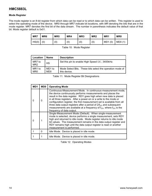
Mode Register<br />
The mode register is an 8-bit register from which data can be read or to which data can be written. This register is used to<br />
select the operating mode of the device. MR0 through MR7 indicate bit locations, with MR denoting the bits that are in the<br />
mode register. MR7 denotes the first bit of the data stream. The number in parenthesis indicates the default value of that<br />
bit. Mode register default is 0x01.<br />
MR7 MR6 MR5 MR4 MR3 MR2 MR1 MR0<br />
HS(0) (0) (0) (0) (0) (0) MD1 (0) MD0 (1)<br />
Table 10: Mode Register<br />
Location Name Description<br />
MR7 to<br />
MR2<br />
MR1 to<br />
MR0<br />
HS<br />
MD1 to<br />
MD0<br />
Set this pin to enable High Speed I2C, 3400kHz.<br />
Mode Select Bits. These bits select the operation mode of<br />
this device.<br />
Table 11: Mode Register Bit Designations<br />
MD1 MD0 Operating Mode<br />
0 0<br />
0 1<br />
Continuous-Measurement Mode. In continuous-measurement mode,<br />
the device continuously performs measurements and places the<br />
result in the data register. RDY goes high when new data is placed<br />
in all three registers. After a power-on or a write to the mode or<br />
configuration register, the first measurement set is available from all<br />
three data output registers after a period of 2/f DO and subsequent<br />
measurements are available at a frequency of f DO , where f DO is the<br />
frequency of data output.<br />
Single-Measurement Mode (Default). When single-measurement<br />
mode is selected, device performs a single measurement, sets RDY<br />
high and returned to idle mode. Mode register returns to idle mode<br />
bit values. The measurement remains in the data output register and<br />
RDY remains high until the data output register is read or another<br />
measurement is performed.<br />
1 0 Idle Mode. Device is placed in idle mode.<br />
1 1 Idle Mode. Device is placed in idle mode.<br />
Table 12: Operating Modes<br />
14 www.honeywell.com