Three-Axis Digital Compass IC HMC5883L
Three-Axis Digital Compass IC HMC5883L
Three-Axis Digital Compass IC HMC5883L

Create successful ePaper yourself
Turn your PDF publications into a flip-book with our unique Google optimized e-Paper software.
<strong>HMC5883L</strong><br />
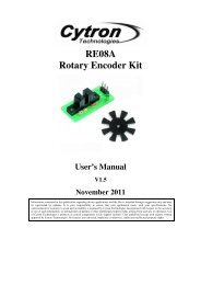
Identification Register A<br />
The identification register A is used to identify the device. IRA0 through IRA7 indicate bit locations, with IRA denoting the<br />
bits that are in the identification register A. IRA7 denotes the first bit of the data stream. The number in parenthesis<br />
indicates the default value of that bit.<br />
The identification value for this device is stored in this register. This is a read-only register.<br />
Register values. ASCII value H<br />
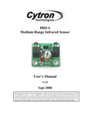
Identification Register B<br />
IRA7 IRA6 IRA5 IRA4 IRA3 IRA2 IRA1 IRA0<br />
0 1 0 0 1 0 0 0<br />
Table 18: Identification Register A Default Values<br />
The identification register B is used to identify the device. IRB0 through IRB7 indicate bit locations, with IRB denoting the<br />
bits that are in the identification register A. IRB7 denotes the first bit of the data stream.<br />
Register values. ASCII value 4<br />
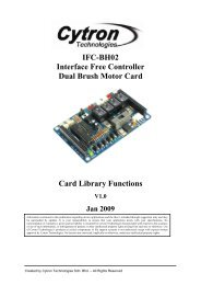
Identification Register C<br />
Table 19: Identification Register B Default Values<br />
The identification register C is used to identify the device. IRC0 through IRC7 indicate bit locations, with IRC denoting the<br />
bits that are in the identification register A. IRC7 denotes the first bit of the data stream.<br />
Register values. ASCII value 3<br />
IRB7 IRB6 IRB5 IRB4 IRB3 IRB2 IRB1 IRB0<br />
0 0 1 1 0 1 0 0<br />
IRC7 IRC6 IRC5 IRC4 IRC3 IRC2 IRC1 IRC0<br />
0 0 1 1 0 0 1 1<br />
I 2 C COMMUN<strong>IC</strong>ATION PROTOCOL<br />
Table 20: Identification Register C Default Values<br />
The <strong>HMC5883L</strong> communicates via a two-wire I 2 C bus system as a slave device. The <strong>HMC5883L</strong> uses a simple protocol<br />
with the interface protocol defined by the I 2 C bus specification, and by this document. The data rate is at the standardmode<br />
100kbps or 400kbps rates as defined in the I 2 C Bus Specifications. The bus bit format is an 8-bit Data/Address<br />
send and a 1-bit acknowledge bit. The format of the data bytes (payload) shall be case sensitive ASCII characters or<br />
binary data to the <strong>HMC5883L</strong> slave, and binary data returned. Negative binary values will be in two’s complement form.<br />
The default (factory) <strong>HMC5883L</strong> 8-bit slave address is 0x3C for write operations, or 0x3D for read operations.<br />
The <strong>HMC5883L</strong> Serial Clock (SCL) and Serial Data (SDA) lines require resistive pull-ups (Rp) between the master device<br />
(usually a host microprocessor) and the <strong>HMC5883L</strong>. Pull-up resistance values of about 2.2K to 10K ohms are<br />
recommended with a nominal VDDIO voltage. Other resistor values may be used as defined in the I 2 C Bus Specifications<br />
that can be tied to VDDIO.<br />
The SCL and SDA lines in this bus specification may be connected to multiple devices. The bus can be a single master to<br />
multiple slaves, or it can be a multiple master configuration. All data transfers are initiated by the master device, which is<br />
responsible for generating the clock signal, and the data transfers are 8 bit long. All devices are addressed by I 2 C’s<br />
unique 7-bit address. After each 8-bit transfer, the master device generates a 9 th clock pulse, and releases the SDA line.<br />
The receiving device (addressed slave) will pull the SDA line low to acknowledge (ACK) the successful transfer or leave<br />
the SDA high to negative acknowledge (NACK).<br />
www.honeywell.com 17