Three-Axis Digital Compass IC HMC5883L
Three-Axis Digital Compass IC HMC5883L
Three-Axis Digital Compass IC HMC5883L

Create successful ePaper yourself
Turn your PDF publications into a flip-book with our unique Google optimized e-Paper software.
<strong>HMC5883L</strong><br />
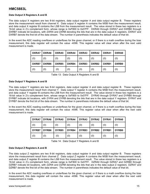
Data Output X Registers A and B<br />
The data output X registers are two 8-bit registers, data output register A and data output register B. These registers<br />
store the measurement result from channel X. Data output X register A contains the MSB from the measurement result,<br />
and data output X register B contains the LSB from the measurement result. The value stored in these two registers is a<br />
16-bit value in 2’s complement form, whose range is 0xF800 to 0x07FF. DXRA0 through DXRA7 and DXRB0 through<br />
DXRB7 indicate bit locations, with DXRA and DXRB denoting the bits that are in the data output X registers. DXRA7 and<br />
DXRB7 denote the first bit of the data stream. The number in parenthesis indicates the default value of that bit.<br />
In the event the ADC reading overflows or underflows for the given channel, or if there is a math overflow during the bias<br />
measurement, this data register will contain the value -4096. This register value will clear when after the next valid<br />
measurement is made.<br />
DXRA7 DXRA6 DXRA5 DXRA4 DXRA3 DXRA2 DXRA1 DXRA0<br />
(0) (0) (0) (0) (0) (0) (0) (0)<br />
DXRB7 DXRB6 DXRB5 DXRB4 DXRB3 DXRB2 DXRB1 DXRB0<br />
(0) (0) (0) (0) (0) (0) (0) (0)<br />
Table 13: Data Output X Registers A and B<br />
Data Output Y Registers A and B<br />
The data output Y registers are two 8-bit registers, data output register A and data output register B. These registers<br />
store the measurement result from channel Y. Data output Y register A contains the MSB from the measurement result,<br />
and data output Y register B contains the LSB from the measurement result. The value stored in these two registers is a<br />
16-bit value in 2’s complement form, whose range is 0xF800 to 0x07FF. DYRA0 through DYRA7 and DYRB0 through<br />
DYRB7 indicate bit locations, with DYRA and DYRB denoting the bits that are in the data output Y registers. DYRA7 and<br />
DYRB7 denote the first bit of the data stream. The number in parenthesis indicates the default value of that bit.<br />
In the event the ADC reading overflows or underflows for the given channel, or if there is a math overflow during the bias<br />
measurement, this data register will contain the value -4096. This register value will clear when after the next valid<br />
measurement is made.<br />
DYRA7 DYRA6 DYRA5 DYRA4 DYRA3 DYRA2 DYRA1 DYRA0<br />
(0) (0) (0) (0) (0) (0) (0) (0)<br />
DYRB7 DYRB6 DYRB5 DYRB4 DYRB3 DYRB2 DYRB1 DYRB0<br />
(0) (0) (0) (0) (0) (0) (0) (0)<br />
Table 14: Data Output Y Registers A and B<br />
Data Output Z Registers A and B<br />
The data output Z registers are two 8-bit registers, data output register A and data output register B. These registers<br />
store the measurement result from channel Z. Data output Z register A contains the MSB from the measurement result,<br />
and data output Z register B contains the LSB from the measurement result. The value stored in these two registers is a<br />
16-bit value in 2’s complement form, whose range is 0xF800 to 0x07FF. DZRA0 through DZRA7 and DZRB0 through<br />
DZRB7 indicate bit locations, with DZRA and DZRB denoting the bits that are in the data output Z registers. DZRA7 and<br />
DZRB7 denote the first bit of the data stream. The number in parenthesis indicates the default value of that bit.<br />
In the event the ADC reading overflows or underflows for the given channel, or if there is a math overflow during the bias<br />
measurement, this data register will contain the value -4096. This register value will clear when after the next valid<br />
measurement is made.<br />
www.honeywell.com 15