Venturi Replacement Kit PSRKIT80 thru 83 - Triangle Tube
Venturi Replacement Kit PSRKIT80 thru 83 - Triangle Tube
Venturi Replacement Kit PSRKIT80 thru 83 - Triangle Tube

Create successful ePaper yourself
Turn your PDF publications into a flip-book with our unique Google optimized e-Paper software.
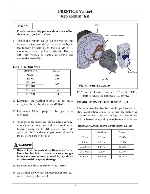
PRESTIGE <strong>Venturi</strong><br />
<strong>Replacement</strong> <strong>Kit</strong><br />
NOTICE<br />
For the reassembly process do not use adhesive<br />
on any gasket surface.<br />
11. Install the venturi gasket on the venturi and<br />
reassemble the venturi / gas valve assembly to<br />
the blower housing using the (2) M5 x 12<br />
mounting screws supplied in the kit. Use the<br />
#25 Torx wrench to tighten all screws and<br />
secure the assembly.<br />
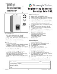
Blower<br />
<strong>Venturi</strong> / Blower Gasket<br />
Table 1: <strong>Venturi</strong> Sizes<br />
PRESTIGE<br />
Model<br />
<strong>Venturi</strong><br />
Size<br />
PS 60 055<br />
PS 110<br />
PE 110<br />
002<br />
PS 175 052<br />
PS 250 051<br />
12. Reconnect the rectifier plug to the gas valve<br />
using the Phillips head screw (MCBA).<br />
13. Reconnect Molex plug to the gas valve<br />
(TriMax).<br />
14. Reconnect the brass gas piping union connection.<br />
Open the main manual gas shutoff valve<br />
before placing the PRESTIGE unit back into<br />
operation check and test all gas connections for<br />
leaks. Repair leaks if found.<br />
WARNING<br />
Do not check for gas leaks with an open flame.<br />
Use a bubble test. Failure to check for gas<br />
leaks can cause severe personal injury, death<br />
or substantial property damage.<br />
<strong>Venturi</strong><br />
Fig. 3: <strong>Venturi</strong> Assembly<br />
17. Turn the electrical power “ON” to the PRES-<br />
TIGE to return the unit back into service.<br />
COMBUSTION TEST/ADJUSTEMENT<br />
Gas Valve<br />
It is recommended that the installer perform a complete<br />
combustion check to ensure the following<br />
combustion levels are met at high and low inputs<br />
and the burner is operating at optimum conditions.<br />
Table 2: Recommended Combustion Levels<br />
Natural Gas<br />
Propane<br />
O2 Min. 2.30% 2.70%<br />
O2 Max. 5.30% 4.70%<br />
CO2 Min. 8.80% 10.70%<br />
CO2 Max. 10.50% 12.00%<br />
CO Max. 100 ppm 100 ppm<br />
15. Reattach the air inlet elbow to the venturi.<br />
16. Reposition the Control Module panel and reattach<br />
the front jacket panel.<br />
3