Chapter 5 Part A: Starting and charging systems
Chapter 5 Part A: Starting and charging systems
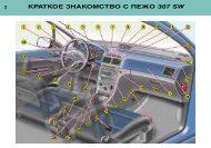
Chapter 5 Part A: Starting and charging systems

You also want an ePaper? Increase the reach of your titles
YUMPU automatically turns print PDFs into web optimized ePapers that Google loves.
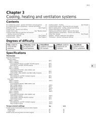
5A•1<br />
<strong>Chapter</strong> 5 <strong>Part</strong> A:<br />
<strong>Starting</strong> <strong>and</strong> <strong>charging</strong> <strong>systems</strong><br />
Contents<br />
Alternator - removal <strong>and</strong> refitting . . . . . . . . . . . . . . . . . . . . . . . . . . . . 6<br />
Alternator - testing <strong>and</strong> overhaul . . . . . . . . . . . . . . . . . . . . . . . . . . . . 7<br />
Auxiliary drivebelt check <strong>and</strong> renewal . . . . . . . . . . . . . . .See <strong>Chapter</strong> 1<br />
Battery - removal <strong>and</strong> refitting . . . . . . . . . . . . . . . . . . . . . . . . . . . . . . 4<br />
Battery - testing <strong>and</strong> <strong>charging</strong> . . . . . . . . . . . . . . . . . . . . . . . . . . . . . . 3<br />
Battery, bulbs <strong>and</strong> fuses . . . . . . . . . . . . . . . . . . . .See “Weekly checks”<br />
Charging system - testing . . . . . . . . . . . . . . . . . . . . . . . . . . . . . . . . . 5<br />
Electrical fault finding - general information . . . . . . . . . . . . . . . . . . . 2<br />
Degrees of difficulty<br />
Easy, suitable for<br />
novice with little<br />
experience<br />
1<br />
Specifications<br />
System type . . . . . . . . . . . . . . . . . . . . . . . . . . . . . . . . . . . . . . . . . . .<br />
Battery<br />
Type . . . . . . . . . . . . . . . . . . . . . . . . . . . . . . . . . . . . . . . . . . . . . . . . . . . .<br />
Capacity . . . . . . . . . . . . . . . . . . . . . . . . . . . . . . . . . . . . . . . . . . . . . . . . .<br />
Charge condition:<br />
Poor . . . . . . . . . . . . . . . . . . . . . . . . . . . . . . . . . . . . . . . . . . . . . . . . . .<br />
Normal . . . . . . . . . . . . . . . . . . . . . . . . . . . . . . . . . . . . . . . . . . . . . . . .<br />
Good . . . . . . . . . . . . . . . . . . . . . . . . . . . . . . . . . . . . . . . . . . . . . . . . . .<br />
1 General information <strong>and</strong><br />
precautions<br />
General information<br />
Fairly easy, suitable<br />
for beginner with<br />
some experience<br />
The engine electrical system consists<br />
mainly of the <strong>charging</strong> <strong>and</strong> starting <strong>systems</strong>.<br />
Because of their engine-related functions,<br />
these components are covered separately<br />
from the body electrical devices such as the<br />
lights, instruments, etc (which are covered in<br />
<strong>Chapter</strong> 12). Information on the ignition<br />
system is covered in <strong>Part</strong> B of this <strong>Chapter</strong>.<br />
The electrical system is of the 12-volt<br />
negative earth type.<br />
The battery is of the low maintenance or<br />
“maintenance-free” (sealed for life) type <strong>and</strong> is<br />
charged by the alternator, which is belt-driven<br />
from the crankshaft pulley.<br />
The starter motor is of the pre-engaged<br />
type incorporating an integral solenoid. On<br />
starting, the solenoid moves the drive pinion<br />
into engagement with the flywheel ring gear<br />
2<br />
Fairly difficult,<br />
suitable for competent<br />
DIY mechanic<br />
Electronic oil level sensor - general information . . . . . . . . . . . . . . . . 13<br />
General information <strong>and</strong> precautions . . . . . . . . . . . . . . . . . . . . . . . . 1<br />
Ignition switch - removal <strong>and</strong> refitting . . . . . . . . . . . . . . . . . . . . . . . . 11<br />
Oil pressure warning light switch - removal <strong>and</strong> refitting . . . . . . . . . 12<br />
Starter motor - removal <strong>and</strong> refitting . . . . . . . . . . . . . . . . . . . . . . . . . 9<br />
Starter motor - testing <strong>and</strong> overhaul . . . . . . . . . . . . . . . . . . . . . . . . . 10<br />
<strong>Starting</strong> system - testing . . . . . . . . . . . . . . . . . . . . . . . . . . . . . . . . . . 8<br />
3<br />
12-volt, negative earth<br />
Low maintenance or “maintenance-free” sealed for life<br />
25 to 33 Ah (depending on model)<br />
12.5 volts<br />
12.6 volts<br />
12.7 volts<br />
before the starter motor is energised. Once<br />
the engine has started, a one-way clutch<br />
prevents the motor armature being driven by<br />
the engine until the pinion disengages from<br />
the flywheel.<br />
Precautions<br />
Further details of the various <strong>systems</strong> are<br />
given in the relevant Sections of this <strong>Chapter</strong>.<br />
While some repair procedures are given, the<br />
usual course of action is to renew the<br />
component concerned. The owner whose<br />
interest extends beyond mere component<br />
renewal should obtain a copy of the<br />
“Automobile Electrical & Electronic Systems<br />
Manual”, available from the publishers of this<br />
manual.<br />
It is necessary to take extra care when<br />
working on the electrical system to avoid<br />
damage to semi-conductor devices (diodes<br />
<strong>and</strong> transistors), <strong>and</strong> to avoid the risk of<br />
personal injury. In addition to the precautions<br />
given in “Safety first!” at the beginning of this<br />
manual, observe the following when working<br />
on the system:<br />
Difficult, suitable for<br />
experienced DIY<br />
mechanic<br />
4<br />
Very difficult,<br />
suitable for expert DIY<br />
or professional<br />
5<br />
Always remove rings, watches, etc before<br />
working on the electrical system. Even with<br />
the battery disconnected, capacitive<br />
discharge could occur if a component’s live<br />
terminal is earthed through a metal object.<br />
This could cause a shock or nasty burn.<br />
Do not reverse the battery connections.<br />
Components such as the alternator, electronic<br />
control units, or any other components having<br />
semi-conductor circuitry could be irreparably<br />
damaged.<br />
If the engine is being started using jump<br />
leads <strong>and</strong> a slave battery, connect the<br />
batteries positive-to-positive <strong>and</strong> negative-tonegative<br />
(see “Booster battery (jump)<br />
starting”). This also applies when connecting<br />
a battery charger.<br />
Never disconnect the battery terminals, the<br />
alternator, any electrical wiring or any test<br />
instruments when the engine is running.<br />
Do not allow the engine to turn the<br />
alternator when the alternator is not<br />
connected.<br />
Never “test” for alternator output by<br />
“flashing” the output lead to earth.<br />
5A
5A•2 <strong>Starting</strong> <strong>and</strong> <strong>charging</strong> <strong>systems</strong><br />
Never use an ohmmeter of the type<br />
incorporating a h<strong>and</strong>-cranked generator for<br />
circuit or continuity testing.<br />
Always ensure that the battery negative<br />
lead is disconnected when working on the<br />
electrical system.<br />
Before using electric-arc welding<br />
equipment on the car, disconnect the battery,<br />
alternator <strong>and</strong> components such as the fuel<br />
injection/ignition electronic control unit to<br />
protect them from the risk of damage.<br />
The radio/cassette units fitted as st<strong>and</strong>ard<br />
or optional equipment may be equipped with a<br />
built-in security code to deter thieves. If the<br />
power source to the unit is cut, the anti-theft<br />
system will activate. Even if the power source<br />
is immediately reconnected, the radio/cassette<br />
unit will not function until the correct security<br />
code has been entered. Therefore, if you do<br />
not know the correct security code for the<br />
radio/cassette unit do not disconnect the<br />
negative terminal of the battery or remove the<br />
radio/cassette unit from the car. Refer to the<br />
Owner’s Manual, or your Peugeot dealer for<br />
further information on security codes.<br />
2 Electrical fault finding -<br />
general information<br />
Refer to <strong>Chapter</strong> 12.<br />
3 Battery - testing <strong>and</strong> <strong>charging</strong><br />
1<br />
St<strong>and</strong>ard <strong>and</strong> low maintenance<br />
battery - testing<br />
1 If the vehicle covers a small annual mileage,<br />
it is worthwhile checking the specific gravity<br />
of the electrolyte every three months to<br />
determine the state of charge of the battery.<br />
Use a hydrometer to make the check <strong>and</strong><br />
compare the results with the following table.<br />
Above Below<br />
25°C (77°F) 25°C (77°F)<br />
Fully-charged 1.210 to 1.230 1.270 to 1.290<br />
70% charged 1.170 to 1.190 1.230 to 1.250<br />
Discharged 1.050 to 1.070 1.110 to 1.130<br />
Note that the specific gravity readings assume<br />
an electrolyte temperature of 15°C (60°F); for<br />
every 10°C (50°F) below 15°C (60°F) subtract<br />
0.007. For every 10°C (50°F) above 15°C<br />
(60°F) add 0.007.<br />
2 If the battery condition is suspect, first<br />
check the specific gravity of electrolyte in<br />
each cell. A variation of 0.040 or more<br />
between any cells indicates loss of electrolyte<br />
or deterioration of the internal plates.<br />
3 If the specific gravity variation is 0.040 or<br />
more, the battery should be renewed. If the<br />
cell variation is satisfactory but the battery is<br />
discharged, it should be charged as<br />
described later in this Section.<br />
Maintenance-free battery -<br />
testing<br />
4 In cases where a “sealed for life”<br />
maintenance-free battery is fitted, topping-up<br />
<strong>and</strong> testing of the electrolyte in each cell is not<br />
possible. The condition of the battery can<br />
therefore only be tested using a battery<br />
condition indicator or a voltmeter.<br />
5 If testing the battery using a voltmeter,<br />
connect the voltmeter across the battery <strong>and</strong><br />
compare the result with those given in the<br />
Specifications under “charge condition”. The<br />
test is only accurate if the battery has not<br />
been subjected to any kind of charge for the<br />
previous six hours. If this is not the case,<br />
switch on the headlights for 30 seconds, then<br />
wait four to five minutes before testing the<br />
battery after switching off the headlights. All<br />
other electrical circuits must be switched off,<br />
so check that the doors <strong>and</strong> tailgate are fully<br />
shut when making the test.<br />
6 If the voltage reading is less than 12.2 volts,<br />
then the battery is discharged, whilst a<br />
reading of 12.2 to 12.4 volts indicates a<br />
partially discharged condition.<br />
7 If the battery is to be charged, remove it<br />
from the vehicle (Section 4) <strong>and</strong> charge it as<br />
described later in this Section.<br />
St<strong>and</strong>ard <strong>and</strong> low maintenance<br />
battery - <strong>charging</strong><br />
Note: The following is intended as a guide<br />
only. Always refer to the manufacturer’s<br />
recommendations (often printed on a label<br />
attached to the battery) before <strong>charging</strong> a<br />
battery.<br />
8 Charge the battery at a rate of 3.5 to 4<br />
amps <strong>and</strong> continue to charge the battery at<br />
this rate until no further rise in specific gravity<br />
is noted over a four hour period.<br />
9 Alternatively, a trickle charger <strong>charging</strong> at<br />
the rate of 1.5 amps can safely be used<br />
overnight.<br />
10 Specially rapid “boost” charges which are<br />
claimed to restore the power of the battery in 1<br />
to 2 hours are not recommended, as they can<br />
cause serious damage to the battery plates<br />
through overheating.<br />
11 While <strong>charging</strong> the battery, note that the<br />
temperature of the electrolyte should never<br />
exceed 37.8°C (100°F).<br />
Maintenance-free battery -<br />
<strong>charging</strong><br />
Note: The following is intended as a guide<br />
only. Always refer to the manufacturer’s<br />
recommendations (often printed on a label<br />
attached to the battery) before <strong>charging</strong> a<br />
battery.<br />
12 This battery type takes considerably<br />
longer to fully recharge than the st<strong>and</strong>ard<br />
type, the time taken being dependent on the<br />
extent of discharge, but it can take anything<br />
up to three days.<br />
13 A constant voltage type charger is<br />
required, to be set, when connected, to 13.9<br />
to 14.9 volts with a charger current below 25<br />
amps. Using this method, the battery should<br />
be usable within three hours, giving a voltage<br />
reading of 12.5 volts, but this is for a partially<br />
discharged battery <strong>and</strong>, as mentioned, full<br />
<strong>charging</strong> can take considerably longer.<br />
14 If the battery is to be charged from a fully<br />
discharged state (condition reading less than<br />
12.2 volts), have it recharged by your Peugeot<br />
dealer or local automotive electrician, as the<br />
charge rate is higher <strong>and</strong> constant supervision<br />
during <strong>charging</strong> is necessary.<br />
4 Battery - removal <strong>and</strong> refitting<br />
1<br />
Note: Make sure that you have a copy of the<br />
radio/cassette unit security code number<br />
(where applicable) before disconnecting the<br />
battery.<br />
Removal<br />
1 The battery is located in the front left-h<strong>and</strong><br />
corner of the engine compartment.<br />
2 Slacken the clamp bolts <strong>and</strong> disconnect the<br />
clamp from the battery negative (earth)<br />
terminal.<br />
3 Remove the insulation cover (where fitted)<br />
<strong>and</strong> disconnect the positive terminal lead(s) in<br />
the same way.<br />
4 Release the battery clamp <strong>and</strong> lift the battery<br />
carefully from the engine compartment.<br />
5 If required, the battery tray can be removed<br />
after undoing the retaining bolts.<br />
Refitting<br />
6 Refitting is a reversal of removal, but smear<br />
petroleum jelly on the terminals when<br />
reconnecting the leads, <strong>and</strong> always reconnect<br />
the positive lead first, <strong>and</strong> the negative lead last.<br />
5 Charging system - testing<br />
1<br />
Note: Refer to the warnings given in “Safety<br />
first!” <strong>and</strong> in Section 1 of this <strong>Chapter</strong> before<br />
starting work.<br />
1 If the ignition warning light fails to illuminate<br />
when the ignition is switched on, first check<br />
the alternator wiring connections for security.<br />
If satisfactory, check that the warning light<br />
bulb has not blown, <strong>and</strong> that the bulbholder is<br />
secure in its location in the instrument panel.<br />
If the light still fails to illuminate, check the<br />
continuity of the warning light feed wire from<br />
the alternator to the bulbholder. If all is<br />
satisfactory, the alternator is at fault <strong>and</strong><br />
should be renewed or taken to an autoelectrician<br />
for testing <strong>and</strong> repair.<br />
2 If the ignition warning light illuminates when<br />
the engine is running, stop the engine <strong>and</strong><br />
check that the drivebelt is correctly tensioned<br />
(see <strong>Chapter</strong> 1) <strong>and</strong> that the alternator<br />
connections are secure. If all is so far<br />
satisfactory, have the alternator checked by<br />
an auto-electrician for testing <strong>and</strong> repair.
<strong>Starting</strong> <strong>and</strong> <strong>charging</strong> <strong>systems</strong> 5A•3<br />
3 If the alternator output is suspect even<br />
though the warning light functions correctly,<br />
the regulated voltage may be checked as<br />
follows.<br />
4 Connect a voltmeter across the battery<br />
terminals <strong>and</strong> start the engine.<br />
5 Increase the engine speed until the<br />
voltmeter reading remains steady; the reading<br />
should be approximately 12 to 13 volts, <strong>and</strong><br />
no more than 14 volts.<br />
6 Switch on as many electrical accessories<br />
(eg, the headlights, heated rear window <strong>and</strong><br />
heater blower) as possible, <strong>and</strong> check that the<br />
alternator maintains the regulated voltage at<br />
around 13 to 14 volts.<br />
7 If the regulated voltage is not as stated, the<br />
fault may be due to worn brushes, weak brush<br />
springs, a faulty voltage regulator, a faulty<br />
diode, a severed phase winding or worn or<br />
damaged slip rings. The alternator should be<br />
renewed or taken to an auto-electrician for<br />
testing <strong>and</strong> repair.<br />
6 Alternator - removal <strong>and</strong><br />
refitting 2<br />
Removal<br />
1 Disconnect the battery negative lead.<br />
2 Remove the auxiliary drivebelt as described<br />
in <strong>Chapter</strong> 1.<br />
3 Where necessary, refer to <strong>Chapter</strong> 4 <strong>and</strong><br />
move the relevant air cleaner components to<br />
one side for increased access.<br />
4 Disconnect the wiring from the alternator<br />
(see illustration).<br />
5 Unscrew the pivot <strong>and</strong> adjustment bolts<br />
<strong>and</strong> lift the alternator from the engine. On<br />
certain models note that the alternator front<br />
bracket is slotted to allow the pivot bolt to<br />
remain in the bracket on the engine.<br />
Refitting<br />
6 Refitting is a reversal of removal, but tension<br />
the drivebelt, as described in <strong>Chapter</strong> 1.<br />
7 Alternator - testing <strong>and</strong><br />
overhaul<br />
5<br />
If the alternator is thought to be suspect, it<br />
should be removed from the vehicle <strong>and</strong> taken<br />
to an auto-electrician for testing. Most autoelectricians<br />
will be able to supply <strong>and</strong> fit<br />
brushes at a reasonable cost. However, check<br />
on the cost of repairs before proceeding as it<br />
may prove more economical to obtain a new<br />
or exchange alternator.<br />
8 <strong>Starting</strong> system - testing<br />
1<br />
Note: Refer to the precautions given in<br />
“Safety first!” <strong>and</strong> in Section 1 of this <strong>Chapter</strong><br />
before starting work.<br />
1 If the starter motor fails to operate when the<br />
ignition key is turned to the appropriate<br />
position, the following possible causes may<br />
be to blame.<br />
a) The battery is faulty.<br />
b) The electrical connections between the<br />
switch, solenoid, battery <strong>and</strong> starter<br />
motor are somewhere failing to pass the<br />
necessary current from the battery<br />
through the starter to earth.<br />
c) The solenoid is faulty.<br />
d) The starter motor is mechanically or<br />
electrically defective.<br />
2 To check the battery, switch on the<br />
headlights. If they dim after a few seconds,<br />
this indicates that the battery is discharged -<br />
recharge (see Section 3) or renew the battery.<br />
If the headlights glow brightly, operate the<br />
ignition switch <strong>and</strong> observe the lights. If they<br />
dim, then this indicates that current is<br />
reaching the starter motor, therefore the fault<br />
must lie in the starter motor. If the lights<br />
continue to glow brightly (<strong>and</strong> no clicking<br />
sound can be heard from the starter motor<br />
solenoid), this indicates that there is a fault in<br />
the circuit or solenoid - see following<br />
paragraphs. If the starter motor turns slowly<br />
when operated, but the battery is in good<br />
condition, then this indicates that either the<br />
starter motor is faulty, or there is considerable<br />
resistance somewhere in the circuit.<br />
3 If a fault in the circuit is suspected,<br />
disconnect the battery leads (including the<br />
earth connection to the body), the<br />
starter/solenoid wiring <strong>and</strong> the<br />
engine/transmission earth strap. Thoroughly<br />
clean the connections, <strong>and</strong> reconnect the<br />
leads <strong>and</strong> wiring, then use a voltmeter or test<br />
lamp to check that full battery voltage is<br />
available at the battery positive lead<br />
connection to the solenoid, <strong>and</strong> that the earth<br />
is sound. Smear petroleum jelly around the<br />
battery terminals to prevent corrosion -<br />
corroded connections are amongst the most<br />
frequent causes of electrical system faults.<br />
4 If the battery <strong>and</strong> all connections are in<br />
good condition, check the circuit by<br />
disconnecting the wire from the solenoid<br />
blade terminal. Connect a voltmeter or test<br />
lamp between the wire end <strong>and</strong> a good earth<br />
(such as the battery negative terminal), <strong>and</strong><br />
check that the wire is live when the ignition<br />
switch is turned to the “start” position. If it is,<br />
then the circuit is sound - if not the circuit<br />
wiring can be checked as described in<br />
<strong>Chapter</strong> 12.<br />
5 The solenoid contacts can be checked by<br />
connecting a voltmeter or test lamp between<br />
the battery positive feed connection on the<br />
starter side of the solenoid, <strong>and</strong> earth. When<br />
the ignition switch is turned to the “start”<br />
position, there should be a reading or lighted<br />
bulb, as applicable. If there is no reading or<br />
lighted bulb, the solenoid is faulty <strong>and</strong> should<br />
be renewed.<br />
6 If the circuit <strong>and</strong> solenoid are proved<br />
sound, the fault must lie in the starter motor.<br />
In this event, it may be possible to have the<br />
starter motor overhauled by a specialist, but<br />
check on the cost of spares before<br />
proceeding, as it may prove more economical<br />
to obtain a new or exchange motor.<br />
9 Starter motor - removal <strong>and</strong><br />
refitting 2<br />
Removal<br />
1 Disconnect the battery negative lead.<br />
2 Where necessary, refer to <strong>Chapter</strong> 4 <strong>and</strong><br />
move the relevant air cleaner components to<br />
one side for increased access.<br />
3 On GTI models, remove the inlet manifold,<br />
with reference to the relevant <strong>Part</strong> of <strong>Chapter</strong><br />
4.<br />
4 Disconnect the wiring from the solenoid<br />
(see illustration).<br />
5 Unscrew the bolts securing the brush end<br />
bracket to the engine (see illustration).<br />
6 Unscrew the mounting bolts at the flywheel<br />
end (see illustration).<br />
7 Withdraw the starter motor from the engine.<br />
6.4 Alternator wiring connections 9.4 Starter motor solenoid wiring<br />
5A
5A•4 <strong>Starting</strong> <strong>and</strong> <strong>charging</strong> <strong>systems</strong><br />
9.5 Starter motor brush end bracket retaining bolts on XV, XW<br />
<strong>and</strong> XY series engines<br />
9.6 Removing the starter motor mounting bolts on XV, XW<br />
<strong>and</strong> XY series engines<br />
Refitting<br />
8 Refitting is a reversal of removal, but first<br />
insert all mounting bolts finger tight, then<br />
tighten the flywheel end bolts followed by the<br />
brush end bolts.<br />
10 Starter motor - testing <strong>and</strong><br />
overhaul 5<br />
If the starter motor is thought to be suspect,<br />
it should be removed from the vehicle <strong>and</strong><br />
taken to an auto-electrician for testing. Most<br />
auto-electricians will be able to supply <strong>and</strong> fit<br />
brushes at a reasonable cost. However, check<br />
on the cost of repairs before proceeding as it<br />
may prove more economical to obtain a new<br />
or exchange motor.<br />
11 Ignition switch - removal <strong>and</strong><br />
refitting 4<br />
The ignition switch is integral with the<br />
steering column lock, <strong>and</strong> can be removed as<br />
described in <strong>Chapter</strong> 10.<br />
12 Oil pressure warning light<br />
switch - removal <strong>and</strong> refitting 2<br />
Removal<br />
1 The switch is located at the front of the<br />
cylinder block, above the oil filter mounting.<br />
Note that on some models access to the<br />
switch may be improved if the vehicle is<br />
jacked up <strong>and</strong> supported on axle st<strong>and</strong>s so<br />
that the switch can be reached from<br />
underneath (see “Jacking <strong>and</strong> vehicle<br />
support”).<br />
2 Disconnect the battery negative lead.<br />
3 Remove the protective sleeve from the<br />
wiring plug (where applicable), then<br />
disconnect the wiring from the switch.<br />
4 Unscrew the switch from the cylinder block,<br />
<strong>and</strong> recover the sealing washer. Be prepared<br />
for oil spillage, <strong>and</strong> if the switch is to be left<br />
removed from the engine for any length of<br />
time, plug the hole in the cylinder block.<br />
Refitting<br />
5 Examine the sealing washer for signs of<br />
damage or deterioration <strong>and</strong> if necessary<br />
renew.<br />
6 Refit the switch, complete with washer, <strong>and</strong><br />
tighten it securely. Reconnect the wiring<br />
connector.<br />
7 Lower the vehicle to the ground then check<br />
<strong>and</strong>, if necessary, top-up the engine oil as<br />
described in “Weekly checks”.<br />
13 Electronic oil level sensor -<br />
general information<br />
1 Some 1985 XU series engine models have<br />
an oil level sensor fitted to the engine sump,<br />
together with a warning lamp on the<br />
instrument panel. The system was only fitted<br />
on the 1985 model year, <strong>and</strong> has been<br />
deleted from later models.<br />
2 The sensor incorporates a high-resistance<br />
wire, which varies in conductivity depending<br />
on whether it is immersed in or above the oil.<br />
An electronic control unit mounted under the<br />
right-h<strong>and</strong> side of the facia monitors the<br />
conductivity, <strong>and</strong> operates the warning lamp<br />
when necessary.<br />
3 It should be noted that the system only<br />
functions accurately if the car is on a level<br />
surface. When the ignition is initially switched<br />
on, the warning lamp should light for two<br />
seconds. If the oil level is correct, the lamp will<br />
then go out, but if it starts to flash the oil level<br />
is low.<br />
4 To prevent the system functioning<br />
unnecessarily after the engine has started, the<br />
control unit is earthed through the oil pressure<br />
switch. The level check is made before<br />
starting the engine. Some early models are<br />
not earthed through the oil pressure switch<br />
<strong>and</strong> on these, the warning lamp may flash if<br />
for instance the engine is temporarily stalled<br />
<strong>and</strong> the oil has not returned to the sump.