Water Tunnel Condition Assessment - Jacobs Associates
Water Tunnel Condition Assessment - Jacobs Associates
Water Tunnel Condition Assessment - Jacobs Associates

You also want an ePaper? Increase the reach of your titles
YUMPU automatically turns print PDFs into web optimized ePapers that Google loves.
<strong>Water</strong> <strong>Tunnel</strong> <strong>Condition</strong> <strong>Assessment</strong>: A Comprehensive Approach to<br />
Evaluating Reliability<br />
By Blake D. Rothfuss, PE, D.WRE<br />
<strong>Jacobs</strong> <strong>Associates</strong><br />
Susan L. Bednarz, RG, CEG<br />
<strong>Jacobs</strong> <strong>Associates</strong><br />
Erin S. Clarke, PE<br />
<strong>Jacobs</strong> <strong>Associates</strong><br />
ABSTRACT: <strong>Water</strong> tunnels present a unique challenge to asset managers as they are very<br />
difficult to evaluate while they are in-service. Whether the water is used for hydroelectric<br />
production or water supply (and sometimes both), water tunnels are essential infrastructure and<br />
expected to maintain the highest reliability. Unfortunately, assessing the condition of a tunnel<br />
and evaluating its reliability requires taking the tunnel out of service for inspection. Satisfying<br />
operational and customer needs can make tunnel outages difficult to schedule, and at best, short<br />
duration events. Once a curtailment is scheduled, inspecting the tunnel presents unique logistical<br />
and safety challenges, further complicating the condition assessment process.<br />
Asset managers need well-executed tunnel condition assessments to develop fiscal projections<br />
and capital improvement programs for their water tunnels. <strong>Water</strong> tunnel reliability projections<br />
must be based on a comprehensive understanding of the water tunnel’s current condition that is<br />
developed by experienced water tunnel engineers. The condition assessment team must be<br />
knowledgeable in water tunnel operations, underground safety, concrete and steel lining<br />
evaluation, historic construction methods, and defect interpretation. This comprehensive<br />
understanding enables the inspection team to quickly assess tunnel conditions and identify issues<br />
important to maintaining reliability.<br />
This paper discusses a water tunnel condition assessment methodology that delivers valuable<br />
planning information for asset managers and operations and maintenance (O&M) managers.<br />
Several applications of the methodology will be discussed, including the condition assessment<br />
objectives, tunnel inspection techniques, underground safety procedures, photographic methods,<br />
and overall condition assessment documentation.<br />
BUSINESS SETTING<br />
Surface water reservoirs may not be co-located adjacent to a hydroelectric generating station or<br />
water treatment facility, necessitating the use of aqueducts to convey water long distances<br />
beneath and above ground. A water conveyance system may consist of tunnels, water control<br />
gates and valves, pipelines (low pressure), ditches, canals, flumes, and penstocks, most of which<br />
can be inspected while the system is in-service or routinely during shutdown periods. <strong>Tunnel</strong>s<br />
1
and related water controls, however, cannot be inspected while in-service and, depending on a<br />
tunnel’s length, may not be safely inspected during a brief shutdown.<br />
Asset managers are dependent on the condition of the water tunnels to meet their customers’<br />
needs and expectations. Sight unseen, operators trust that water flowing into a tunnel will exit at<br />
the downstream end, and flow into the next conveyance element. Similarly, submerged<br />
mechanical controls—e.g., intake gates, control valves, and turbine shutoff valves—must have<br />
the highest reliability when operated. <strong>Tunnel</strong>s, like other critical infrastructure, will deteriorate<br />
with time; however tunnel problems can arise suddenly and immediately interrupt power<br />
generation or water supply. Confident service reliability is only possible through comprehensive<br />
and well-managed asset-based risk management programs. Understanding the condition of a<br />
water tunnel is a critical component of assessing its reliability and fiscal risk.<br />
CONDITION ASSESSMENT OBJECTIVES<br />
At an asset program level, the primary objective is to assess the tunnel’s condition relative to<br />
current operating demands and identify all future major fiscal needs necessary to maintain the<br />
tunnel’s reliability and asset value. An emerging secondary objective is associated with assessing<br />
the tunnel’s future worth. Consideration of future beneficial uses associated with the hydro<br />
development or water supply system may place greater demands on an in-service tunnel.<br />
Maintaining an accurate as-built record of the tunnel facilitates the planning process without<br />
affecting day-to-day water conveyance. Also, in recent years knowledge transfer between<br />
employee generations has also led to increased emphasis on understanding out-of-sight assets<br />
such as tunnels.<br />
Once the asset program manager has determined that additional information is needed, a projectspecific<br />
water tunnel condition assessment can be planned. Typical objectives include the<br />
following.<br />
Work safely. <strong>Water</strong> tunnels present tunnel inspectors and their support crews with numerous<br />
operational and weather-related hazards. <strong>Tunnel</strong>s should be considered as permit-required<br />
confined spaces, and the tunnel inspection should be carefully planned and executed with<br />
extreme discipline. An injury or illness within a water tunnel can be potentially fatal.<br />
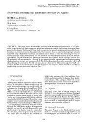
Document the condition of the tunnel. A tunnel may be inspected in a watered or unwatered<br />
state, and at varying levels of detail. The benefits and shortcomings associated with each method<br />
should be considered early in the planning process. These observations can confirm whether the<br />
tunnel and associated mechanical systems can be depended upon or they can identify necessary<br />
improvements, see Figures 1 through 4.<br />
Prioritize any deficiencies relative to potential impacts on reliability and efficiency.<br />
Rockfalls within the tunnel may increase hydraulic head losses and reduce the generating<br />
station’s efficiency. Structural lining defects may influence long-term maintenance costs on<br />
turbines or may create sudden and catastrophic ground instabilities, forcing an outage.<br />
2
Develop a plan to access and repair the deficiencies. The repair plan should include<br />
engineered repair requirements, a schedule plan, and outage requirements. <strong>Tunnel</strong> repairs can<br />
present significant logistical challenges. Repair work should be planned assuming very limited<br />
outage windows and 24-hour workdays. Personnel, materials, and equipment movements should<br />
be carefully choreographed as most of the repairs rely on a single access point and long travel<br />
distances to the repair locations. Cost estimates should include reasonable contingencies for<br />
weather, water control, material availability, design efficiency, and inflation.<br />
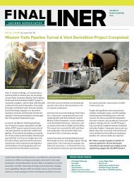
Figure 1. Identified leaking intake gate seal<br />
or obstruction in the waterway<br />
Figure 2. Confirmation that the surge tank is<br />
in operable condition<br />
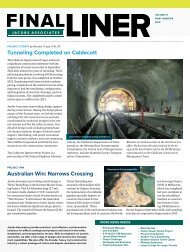
Figure 3. Identification of tunnel lining repairs<br />
3
Figure 4. Inspected butterfly valve<br />
Estimate the remaining dependable service life with and without repairs. If consecutive and<br />
comparable tunnel condition assessments are available, a rate of deterioration can be used to<br />
estimate the tunnel’s remaining dependable service life.<br />
Integrate the planning information into the asset management plan. The repair costs may be<br />
easily included in the current work plan or next year’s budget or may require 5 to 10 years to<br />
implement. In some cases, the planning for a replacement tunnel may be appropriate.<br />
UNDERGROUND SAFETY PROCEDURES<br />
Identify Hazards and Mitigation Measures<br />
Safety must be a high priority for all tunnel inspections. Safety regulations applicable to<br />
inspecting in-service water tunnels must be considered during the planning phase of the<br />
condition assessment. In the United States, the provisions of the General Industry Safety Orders<br />
(29 CFR 1910) apply to the inspection of tunnels, and the provision of the Construction Safety<br />
Orders (29 CFR 1926) apply to the construction of tunnels. Three primary hazards, which are<br />
common to all unwatered tunnel inspections, must be considered: tunnel instability, atmospheric<br />
hazards immediately dangerous to life or health (IDLH), and operational hazards. These, and any<br />
other hazards identified through a job hazard assessment, must be mitigated prior to and<br />
throughout the inspection.<br />
<strong>Tunnel</strong> Instability. Engineers experienced in underground engineering and construction should<br />
watch for localized tunnel instability throughout the inspection. They should look for signs of<br />
structural distress in the rock and structural linings. Crack patterns can often identify hazard<br />
areas that can be avoided during the inspection.<br />
4
Atmospheric Hazards. Any source of airborne contaminants or toxic vapors must be kept far<br />
away from the tunnel air inlets to ensure that fresh air is drawn into the tunnel as it is drained.<br />
Exhaust from motor vehicles, generators, and compressors cannot be drawn into the tunnel<br />
during draining. Also, toxic hydrogen sulfide gas (H 2 S) or explosive gas may be encountered<br />
underground. Most atmospheric hazards can be resolved by using fans and natural ventilation.<br />
Table 1 presents an atmospheric monitoring worksheet.<br />
Operational Hazards. The most significant operational hazard on most water tunnel inspections<br />
is the potential for flooding. Flooding can be prevented by effectively using lockout-tagout<br />
(LOTO) protocols that isolate reservoirs from the tunnel being inspected. Two forms of LOTO<br />
exist in most agencies: physical and administrative. Administrative LOTO places a clearance tag<br />
or man-on-line tag (typically paper) on equipment control surfaces. Operators are trained not to<br />
place equipment in service if a tag is present. Physical LOTO requires that equipment be<br />
temporarily disabled or prevented (by locking) from operating. A combination of administrative<br />
and physical LOTO methods is particularly effective in hydro and water supply systems.<br />
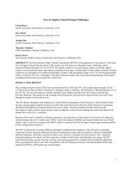
Differing Site <strong>Condition</strong>s. The job hazards assessment should identify all of the potential<br />
hazards tunnel inspectors may be exposed to; however, in tunnels that have not been recently<br />
inspected, actual site conditions may be different than anticipated. The lead inspector should be<br />
authorized to postpone or alter the inspection plan in the event that actual conditions are too<br />
hazardous. In most cases, well-prepared inspectors can adapt to different conditions, as was the<br />
case when very slippery mud was encountered in a water tunnel (see Figure 5).<br />
5
Table 3-1<br />
Table 1. Atmospheric Monitoring Record<br />
Station Time Air Speed*<br />
(fpm)<br />
Air Flow<br />
(cfm)<br />
O2<br />
(%)<br />
CO<br />
(ppm)<br />
H2S<br />
(ppm)<br />
LEL<br />
(%)<br />
Temp<br />
( o F)<br />
Press.<br />
(mm Hg)<br />
Exterior, Adit 1 0728 N/R N/R 20.9 0 0 0 40 27.85<br />
Interior, Adit 1 0728 N/R N/R 20.7 0 0 0 N/R N/R<br />
Sta. 566 0813 N/R N/R 20.4 0 0 0 N/R N/R<br />
Sta. 600 0830 No radio contact with adit<br />
Sta. 682+50 0858 N/R N/R 20.9 0 0 0 N/R N/R<br />
Sta. 700 0908 180 4,500 20.7 0 0 0 56 27.9<br />
Sta. 730 1020 170 4,250 20.9 0 0 0 61 27.9<br />
Sta. 756 1058 92 2,300 20.7 0 0 0 56 N/R<br />
Sta. 764+71 1111 N/R N/R N/R N/R N/R N/R N/R N/R<br />
Sta. 800 1145 N/R N/R 20.7 0 0 0 N/R N/R<br />
Sta. 819 1215 N/R N/R 20.7 0 0 0 N/R N/R<br />
Weep hole @ 3 o’clock producing water + gas<br />
Sta. 856 1258 130 3,250 20.7 0 0 0 55 27.8<br />
Sta. 900 1428 150 3,750 20.7 0 0 0 57 27.8<br />
Sta. 968+30 1649 N/R N/R 20.9 0 0 0 56 N/R<br />
Adit 2 1823 N/R N/R 20.9 0 0 0 N/R N/R<br />
* Natural ventilation only.<br />
N/R = Not Recorded<br />
6
Figure 5. Very slippery mud encountered in a water tunnel<br />
Six inches (150 mm) of mud in this unlined tunnel were an unanticipated hazard and created<br />
continuous slip and fall hazards for several miles. Inspectors used walking sticks to help<br />
maintain their stability.<br />
Safety Preparations<br />
Communication<br />
Communication between the surface support team and tunnel entrants is typically problematic<br />
during long in-service water tunnel inspections. The inspection team should carry radios for<br />
voice communication, but the range may be limited to less than about 1.6 miles (2.5 km) and will<br />
be significantly affected by tunnel bends. Air horns have been used effectively in concrete-lined<br />
tunnels to signal safety team members, but a horn’s effectiveness can be significantly affected by<br />
unlined rock tunnel surface irregularities.<br />
To safeguard the inspection team in the event that communication is lost during an underground<br />
emergency, the inspection party should include at least two people trained in first aid. The<br />
inspection team should be large enough that two entrants could be sent for help if needed, while<br />
the remainder of the inspection team can attend to an injured inspector.<br />
7
Safety Instruction<br />
Prior to entering the tunnel, all tunnel entrants and the support team should participate in an<br />
extended safety tailgate meeting. The agenda includes the following topics: purpose of<br />
inspection, access, anticipated conditions, safety procedures, communication, accident<br />
prevention, and emergency response procedures.<br />
Personal Protective Equipment<br />
Personal protective equipment for the tunnel entrants is selected to protect against the identified<br />
hazards. A comprehensive list of the required personal protective equipment is included in<br />
Appendix A.<br />
Pre-entry Activities and Monitoring during Inspection<br />
Prior to entering the tunnel, a permit required confined space permit must be completed. The<br />
permit includes essential information about the inspection, including the hazards assessment,<br />
incident action plan, communication plan, LOTO procedures, personnel accountability plan,<br />
personal protective equipment list, and atmospheric monitoring equipment list. A sample permit<br />
is included in Appendix B.<br />
In inverted siphon tunnels, provisions to pump out the tunnel and remove residual leakage may<br />
require significant planning and involve water discharge permits. Figure 6 illustrates a<br />
submersible pump and backup required to drain a tunnel for inspection.<br />
8
Figure 6. Submersible pumps may be required to unwater a tunnel prior to inspection<br />
TUNNEL INSPECTION TECHNIQUES<br />
The inspection team may consist of two functional groups—a survey group and a condition<br />
assessment (CA) group.<br />
<br />
<br />
The survey group is responsible for the inspection navigation. It leads the inspection<br />
team, identifies significant hazards, and establishes tunnel stationing.<br />
The CA group is responsible for assessing the condition of the tunnel. It interprets the<br />
geologic conditions; sounds out the concrete lining to identify structurally inadequate<br />
concrete sections and voids behind the lining; classifies the defects; counts defects and<br />
voids; measures water infiltration flows; records the sizes and orientations of defects and<br />
cavities; and photographs and videotapes the tunnel’s condition.<br />
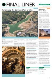
SURVEY METHODOLOGY<br />
The survey group leads and sets the pace for the inspection team, stations the tunnel, and warns<br />
the CA group of any significant hazards. Based upon as-built drawings and landmarks (see<br />
Figure 7) within the tunnel, the survey group stations the tunnel and locates key features. This<br />
effort aligns the inspectors’ observations with the tunnel stationing. At 100-foot (33.3 m)<br />
intervals, the tunnel stationing should be marked on the walls with spray paint (NSF 61<br />
compliant) or crayons. <strong>Tunnel</strong> stations should also be determined for the beginning and end of<br />
9
each concrete tunnel section. The survey group may also install permanent station markers to<br />
assist future inspections.<br />
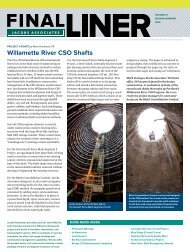
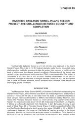
The inspection team’s pace will vary dramatically depending upon the tunnel invert’s condition<br />
and the distribution of defects. Inspection paces for unlined tunnels range between 1,500 and<br />
2,000 feet per hour (f/h) (457 and 610 m/h). Inspection rates for lined tunnels range between<br />
2,500 to 3,500 f/h (762 and 1,067 m/h). Figure 8 compares the planned pace with the actual<br />
inspection pace for a tunnel inspection where the number of defects per 100 feet (33.3 m)<br />
increased in the downstream tunnel reach.<br />
Figure 7. <strong>Tunnel</strong> station marker installed during construction and used by tunnel inspectors<br />
during the condition assessment<br />
10
6:00 AM<br />
7:00 AM<br />
8:00 AM<br />
9:00 AM<br />
10:00 AM<br />
11:00 AM<br />
12:00 PM<br />
1:00 PM<br />
2:00 PM<br />
3:00 PM<br />
4:00 PM<br />
5:00 PM<br />
6:00 PM<br />
7:00 PM<br />
8:00 PM<br />
Time<br />
Stationing<br />
239+00 339+00 439+00 539+00 639+00 739+00 839+00 939+00<br />
Team 1, Planned<br />
Team 1, Actual<br />
Figure 8. Comparison of planned and actual inspection pace<br />
CONDITION ASSESSMENT METHODOLOGY<br />
To improve consistency among all the tunnel inspectors, a key to descriptive terms is used to<br />
describe the observations. The key provides multiple descriptive terms for: orientation<br />
(inspection direction and dimensioning); tunnel configuration (circular, horseshoe, or<br />
rectangular); lined/unlined tunnel characteristics (lining type, lining condition, dimensions,<br />
surface roughness, corrosion, water infiltration, defect classification, rock joint patterns, and rock<br />
integrity).<br />
Defect Classifications<br />
Four categories of defects and voids are defined to allow the inspectors to consistently document<br />
their observations. Defects are defined as any failure of the structural lining system, ranging from<br />
a shallow pocket to a hole in the unreinforced concrete lining. A void or cavity is defined as any<br />
space between the rock-side of the concrete lining and the rock surface. Defects are classified<br />
into four types, ranging from the least significant (Type I) to the most significant (Type IV). To<br />
further refine the defect descriptions, the team may choose to add descriptors such as rock<br />
pockets or sloped defects. A rock pocket is a portion of the lining in which poorly cemented<br />
aggregates are visible and readily removed by hand. Rock pockets are typically Type I, II, or III<br />
defects. A sloped defect, typically associated with concrete placement inconsistencies, is oriented<br />
at an angle of between 15 and 30 degrees to the horizontal and may be a Type II, III, or IV<br />
defect. Figures 9 through 12 illustrate the defect types, and Figures 13 and 14 illustrate how the<br />
defects were distributed in one inspected water tunnel. This type of analysis is essential to rating<br />
the condition of the tunnel by reach and developing a repair cost estimate.<br />
11
Type I Defect<br />
<br />
<br />
Defects do not affect the operational reliability, watertightness, or structural integrity of<br />
the tunnel.<br />
Defects may include closed or tight circumferential temperature shrinkage cracks and<br />
shallow voids in the structural concrete lining.<br />
Figure 9. Type I Defect: Sloping defects along concrete placement layers<br />
Type II Defect<br />
<br />
<br />
Defects are generally not considered to affect the operational reliability. Depending on<br />
the distribution and frequency, clusters of this defect type may reduce the structural<br />
capacity of the tunnel lining system.<br />
Defects may include circumferential cracks that are open and sharp edged. Voids may<br />
extend well into the structural lining system.<br />
12
Figure 10. Poorly cemented concrete at a construction joint<br />
Type III Defect<br />
<br />
<br />
If isolated, this defect type is not considered to affect the operational reliability. However,<br />
if clustered, this defect type may have compromised the tunnel’s structural support<br />
system locally.<br />
The structural support system has been interrupted by a void or defect, preventing the<br />
effective resolution of ground and water loads. A void in the concrete tunnel liner is of<br />
full thickness, and the rock or soil is exposed.<br />
Figure 11. Poorly cemented concrete has eroded through the full liner thickness<br />
Type IV Defect<br />
13
This defect type will affect the operational reliability and has compromised the tunnel’s<br />
structural support system.<br />
The structural support system has been interrupted by a void or defect, preventing the<br />
effective resolution of ground and water loads. This defect type is characterized by the<br />
presence of a cavity behind the tunnel liner coupled with a full thickness void in the<br />
concrete tunnel liner. This condition creates asymmetrical loading on a compromised<br />
structural support system.<br />
Figure 12. Defect and outlined cavity behind liner in a concrete-lined pressure tunnel, circa 1925<br />
construction<br />
14
Figure 13. Defect distribution per 100 feet (33.3 m)<br />
Figure 14. Estimated volume of defects and voids per 100 feet (33.3 m)<br />
15
<strong>Water</strong> Infiltration Classifications<br />
Leaks in the tunnel identify breaches in the lining watertightness. During normal operations, the<br />
differential pressure between the in-service tunnel and the groundwater will govern whether<br />
water is infiltrating or exfiltrating from the tunnel. Infiltrating water may affect the tunnel’s<br />
water quality, and exfiltrating water may affect groundwater levels or create localized ground<br />
instability. Locating these features relative to surface structures should be considered in the<br />
condition assessment. The inspectors should classify and measure the leakage.<br />
<strong>Condition</strong> <strong>Assessment</strong> Ratings<br />
The overall condition assessment rating will depend on the type, size, distribution, frequency,<br />
and location of defects or anomalies found in the tunnel. Evaluating the significance of a defect<br />
demands a comprehensive understanding of how the tunnel or specific structural element in the<br />
tunnel was designed and its intended function. <strong>Water</strong> tunnel reaches are rated as excellent, good,<br />
fair, poor, and critical depending upon the tunnel’s condition. For water tunnels, the qualitative<br />
rating is based on the following.<br />
<br />
<br />
<br />
<br />
<br />
<br />
<br />
Structural integrity of the waterway which considers condition of the concrete lining,<br />
steel lining, timber supports and lining, or rock integrity;<br />
Hydraulic performance of the waterway which considers the hydraulic roughness,<br />
obstructions, and transitions;<br />
Remaining capacity of rock traps, sumps, and drain lines;<br />
<strong>Water</strong>tightness which considers water loss or gain, and the potential for hydraulic piping;<br />
Operability of mechanical systems like slide and roller gates, gate and butterfly valves,<br />
and pumps;<br />
Operability of instrumentation and control systems like flow meters and water level<br />
meters;<br />
Erodible material which may be mobilized and scour concrete inverts, erode penstock<br />
linings, or increase wear in pumps or turbines.<br />
This rating system was adapted from the U.S. Highway and Rail Transit <strong>Tunnel</strong> Inspection<br />
Manual (2005). Figures 15 through 19 illustrate how the condition assessment ratings can be<br />
applied to an in-service water tunnel.<br />
Excellent <strong>Condition</strong><br />
<br />
The in-service tunnel is in a like-new condition and is functioning as originally designed.<br />
16
There are no identified defects or anomalies.<br />
The tunnel is watertight. This level of service assumes that minor seepage may be present<br />
at tunnel portals and adits.<br />
The tunnel is in-service at full capacity. Confidence is high that the tunnel’s operational<br />
reliability will remain high over the tunnel’s life.<br />
Figure 15 is an image of a tunnel in excellent condition.<br />
Figure 15. <strong>Tunnel</strong> transition from unlined to lined reaches<br />
Good <strong>Condition</strong><br />
<br />
<br />
<br />
The in-service tunnel is no longer in like-new condition and is functioning as originally<br />
designed.<br />
Isolated defects are present but there are no observed systemic patterns to any defect<br />
distribution or frequency. Defects may include circumferential temperature shrinkage<br />
cracks or isolated single rock falls. Repairs are not warranted.<br />
The tunnel is watertight. This level of service assumes that minor seepage may be present<br />
at tunnel portals and adits.<br />
17
The tunnel should be re-inspected within 10 years.<br />
The tunnel remains in-service at full capacity. Confidence is high that the tunnel’s<br />
operational reliability will remain high over the tunnel’s life.<br />
Figures 16 (a) and (b) are images of a tunnel in good condition.<br />
Figure 16. (a) Typical lined horseshoe tunnel section<br />
Figure 16 (b). Typical concrete-lined tunnel section<br />
18
Fair <strong>Condition</strong><br />
<br />
<br />
<br />
<br />
<br />
<br />
The in-service tunnel or section of tunnel is functioning as originally designed.<br />
Defects or anomalies are present and may be systemic. Defect size and frequency may<br />
range from minor and random (Type 1 defect), to moderate and repeating (Type 2<br />
defect), to severe and isolated (Type 3 or 4 defect). Circumferential cracks may be open<br />
and sharp edged. Longitudinal cracks may be present but do not show active movement.<br />
Localized erosion or scour areas may be present. Rock falls may be present on the tunnel<br />
invert but do not obstruct the flow.<br />
Repairs may not be required immediately but should be planned for within 5 to 10 years.<br />
The tunnel is moderately watertight. Leakage should be measured and monitored<br />
routinely. This level of service assumes that leakage may be present at tunnel portals and<br />
adits.<br />
The tunnel should be re-inspected within 5 years to assess the rate of defect deterioration.<br />
The tunnel remains in-service at full capacity. Confidence is moderate that the<br />
tunnel’s operational reliability will be sustainable over the tunnel’s life.<br />
Figure 17 is an image of a tunnel in fair condition.<br />
a<br />
b<br />
Figure 17. (a) Tubercle over cement mortar-lined (CML) steel tunnel liner; (b) revealed pit<br />
corrosion beneath tubercle and CML<br />
19
Poor <strong>Condition</strong><br />
<br />
<br />
<br />
<br />
<br />
<br />
<br />
The in-service tunnel or section of tunnel is not functioning as originally designed.<br />
Significant and numerous defects are present, jeopardizing the continued operation,<br />
watertightness or structural integrity of the tunnel.<br />
Defect size and frequency may range from minor and random (Type 1 defect), moderate<br />
and repeating (Type 2 defect) to severe and repeating (Type 3 or 4 defect).<br />
Circumferential and longitudinal cracks may be open and sharp edged. Open cracks my<br />
produce significant volumes of calcite, silty sand or clay. Localized erosion or scour<br />
areas may be present. Unlined tunnel instability has generated rock falls that affect water<br />
flow.<br />
Immediate mitigation is prudent and should include developing a risk assessment of the<br />
tunnel operations, implementing a monitoring plan to evaluate the operating<br />
characteristics, designing a contingency plan, and planning for a repair outage within 5 to<br />
10 years.<br />
The tunnel may not be watertight. Leakage at tunnel portals and adits maybe excessive.<br />
Unexplained water courses near portals or along low-cover portions of the tunnel may be<br />
telltale signs of a tunnel breach, sinkhole, or other ground instability.<br />
The tunnel should be re-inspected within 2 years to assess the rate of defect deterioration.<br />
The tunnel remains in-service at full or partial capacity. Confidence is low that the<br />
tunnel’s operational reliability will be sustainable over the tunnel’s life without repairs.<br />
Figure 18 shows a void and cavity that are suspected of being the source of leakage daylighting<br />
near the tunnel’s downstream portal. Longitudinal cracks run upstream and downstream. This<br />
water tunnel was inspected by a remotely operated vehicle (ROV) because system demands<br />
prevented an outage.<br />
20
Figure 18. Void and cavity, located in the tunnel’s crown<br />
Critical <strong>Condition</strong><br />
<br />
<br />
<br />
<br />
<br />
The in-service tunnel or section of tunnel is not functioning as originally designed.<br />
Critical defects are present, jeopardizing the continued operation, watertightness or<br />
structural integrity of the tunnel.<br />
Immediate action is prudent and should include implementing an operations contingency<br />
plan and repairs, as appropriate.<br />
The tunnel should be re-inspected within 2 years to assess the rate of defect deterioration.<br />
The tunnel poses a high level of risk if it remains in-service at full or partial<br />
capacity.<br />
No photograph is available of a tunnel in critical condition.<br />
21
PHOTOGRAPHIC METHODS<br />
Documenting a tunnel condition assessment using photographs and videography can<br />
significantly enhance a comprehensive water tunnel condition assessment. The high quality of<br />
the images in this paper is the result of the photographers’ experience, equipment, and technique.<br />
Asset managers, operators, engineers, and contractors all benefit from high-quality, underground<br />
photographs that accurately represent the condition and and accessibility of the underground<br />
facilities. The challenge is to take high-quality inspection photographs while walking through a<br />
slippery, pitch-black tunnel with a foot or two of water in the invert plus water spraying in from<br />
the sidewall and crown.<br />
Many common underground photo problems can be minimized through equipment and technique<br />
adjustments.<br />
Equipment<br />
Camera. Using a digital SLR camera and high-quality lenses greatly improves the quality of the<br />
underground images; however, point-and-shoot cameras can also take excellent images under<br />
optimum conditions. Both systems have problems photographing reflective, moving subjects in<br />
dark, humid, or dusty environments.<br />
Media Storage. One of the benefits of using digital photography is the ability to take an<br />
“infinite” number of pictures then selectively choose the best ones. Prior to the tunnel inspection,<br />
obtain several large-capacity media storage cards and seal them in double zip-lock plastic bags to<br />
waterproof them. Multiple cards provide redundancy storage media in the event a card is<br />
damaged during the inspection.<br />
Auxiliary Flash. Insufficient camera flash will light only a small portion of the scene. Auxiliary<br />
flashes are usually more powerful than integrated camera flashes. Connecting an external strobe<br />
flash to your camera will increase light output and scene illumination. Powerful strobe flashes<br />
that can light up 40 feet (12 m) of tunnel are lightweight and portable. Pivot head flashes also<br />
allow the photographer to vary flash illumination to accent specific tunnel or mechanical<br />
equipment features.<br />
Wide Angle Lens. Sometimes the scene is too big to fit into the viewfinder, as is the case with<br />
the surge tank in Figure 2. Most point and shoot cameras don’t have integral wide angle lenses<br />
that can capture the entire scene. Select a camera or lens that has the widest possible focal length.<br />
A 16 mm focal length lens provides an adequate field of view for most underground<br />
photography.<br />
Protecting Equipment. Long tunnel inspections require the underground photographer to carry<br />
all of his or her equipment for long durations. Damaged equipment is useless and a burden.<br />
Protect equipment from water vapor and spraying water by using a waterproof or water resistant<br />
camera, lenses, and strobe flash. Enclosing equipment in a watertight camera bag or a bag with a<br />
22
waterproof cover also helps, as does using a walking stick to probe ahead for depressions when<br />
water is present on the tunnel invert.<br />
Technique<br />
Choosing the “Right” Shot. The underground photographer will be documenting elements of<br />
the tunnel that few people will ever see in person. Consider the interests the asset manager or<br />
bureau chief may have when planning for and justifying tunnel rehabilitation projects. Frame the<br />
pictures to show the general condition of the tunnel, and provide sufficient detail to reassure<br />
those who will not have the opportunity to be in the tunnel that it is in excellent condition or to<br />
convince them that the deteriorated condition is real and may jeopardize future reliability.<br />
Camera Stabilization. Blurry images caused by camera shake or moving equipment and<br />
workers can ruin a photograph. Mount the camera on a tripod to eliminate camera shake. New<br />
cameras and lenses with image stabilization help to reduce camera shake. To reduce blurring<br />
from moving equipment and workers, increase the ISO setting and open the lens aperture to its<br />
widest opening. Use a minimum shutter speed of 1/125th second for hand-held photographs to<br />
reduce motion blur.<br />
Image Clarity. Dust, tiny airborne water droplets, water vapor, and exhaled breath can obscure<br />
the image with spots or reflections. To solve the problem, use an external flash that is connected<br />
to the camera by a cord and aim the flash at an angle to the axis of the photograph. The flash no<br />
longer reflects off the dust and water vapor into the lens and the reflections disappear. Exhaling<br />
and brief breath holding will allow exhaled breath to move away from the flash and reduce the<br />
“white-out” in an image.<br />
Reducing Safety Vest Reflections. There are three approaches to avoid photographs in which<br />
the only the reflective vest stripes are visible. They include not using a flash, moving the flash<br />
off the camera, and using a high-end, camera-mounted strobe flash that compensates for the<br />
reflective stripes.<br />
Scale the Image. Sometimes the photographed feature lacks a scaling feature, making the<br />
interpretation and analysis difficult. Include a photographic scale, a black and white scale rod,<br />
measuring tape, or other object to provide scale and perspective to the scene. The scale also<br />
provides a convenient focal point for many auto focus camera lenses.<br />
Earmark the Image. Log the pictures taken during the inspection and include the camera’s<br />
image number and tunnel station where the picture was taken. The combination of the date/time<br />
stamped image and the tunnel station allow the tunnel engineer to produce an accurate as-built<br />
record and condition assessment.<br />
23
SUMMARY<br />
Many of the existing conveyance systems in North America are approaching the sunset of their<br />
original design life without formal assessment of their current condition. There may be some<br />
systems that have not been thoroughly inspected since they were put in service. Thorough<br />
condition assessments provide essential planning information for asset management programs.<br />
Unwatered tunnel inspections allow tunnel inspectors to obtain extensive observational and<br />
nondestructive information of an in-service water tunnel. The inspection can be accomplished<br />
safely and at an acceptable cost when properly planned and executed. These programs can<br />
greatly increase a utility’s ability to provide reliable service, anticipate future fiscal demands,<br />
and meet customer expectations.<br />
REFERENCES<br />
American Society of Civil Engineers Task Committee, “Guideline for the Evaluation of <strong>Water</strong><br />
Conveyance <strong>Tunnel</strong>s”, (Draft)<br />
NSF/ANSI Standard 61, “Drinking <strong>Water</strong> System Components” (1988).<br />
“Occupational Safety and Health Standards,” Code of Federal Regulations. Title 29, Pt. 1910<br />
(2010).<br />
“Safety and Health Regulations for Construction,” Code of Federal Regulations. Title 29, Pt.<br />
1926 (2010).<br />
U.S. Department of Transportation. 2005. U.S. Highway and Rail Transit <strong>Tunnel</strong> Inspection<br />
Manual (2005).<br />
ACKNOWLEDGEMENTS<br />
The authors appreciate the support of the San Francisco Public Utilities Commission, Seattle<br />
City Lights, Puget Sound Energy, and the South Central Connecticut Regional <strong>Water</strong> Authority.<br />
BIOGRAPHIES<br />
Blake Rothfuss is a Lead Associate and Corporate Safety Manager with <strong>Jacobs</strong> <strong>Associates</strong><br />
where he specializes in hydroelectric project design and construction, and water tunnel<br />
rehabilitation. Over his career, Blake has had extensive experience in water resources<br />
engineering, underwater inspection and construction, and managing heavy construction projects.<br />
Sue Bednarz is a Project Geologist with <strong>Jacobs</strong> <strong>Associates</strong> where she specializes in field<br />
exploration and design for tunnels, pipelines, and highways. Sue is a recognized expert in<br />
construction and inspection photography.<br />
Erin Clarke is a Staff Engineer with <strong>Jacobs</strong> <strong>Associates</strong> where she specializes in the design and<br />
construction of underground structures.<br />
24
APPENDIX A: RECOMMENDED TUNNEL INSPECTOR’S<br />
PERSONAL PROTECTIVE EQUIPMENT<br />
Individual equipment that should be worn or carried<br />
<br />
<br />
<br />
<br />
<br />
<br />
<br />
<br />
<br />
<br />
<br />
<br />
<br />
<br />
Hard hat<br />
Hard hat mounted light (700 lumen output recommended)<br />
Backup flashlights and spare batteries<br />
Safety glasses, clear<br />
Gloves, mechanics style, synthetic<br />
Warm clothes, synthetic or wool (no cotton)<br />
<strong>Water</strong> repellant jacket<br />
Walking sticks (required in unlined tunnels, useful in lined tunnels)<br />
Sturdy boots (hip or chest waders recommended)<br />
Emergency whistle<br />
Personal first aid kit (blister kit, bleeding control kit)<br />
Snacks and water<br />
Hand cleaner/sanitizer<br />
Extra ziplock plastic bags, 1 gallon<br />
Group equipment<br />
<br />
<br />
<br />
Atmospheric monitoring meters (O 2 , CO, H 2 S, LEL)<br />
Air speed meter<br />
Communication: Air horns and radio<br />
25
APPENDIX B: SAMPLE TUNNEL AND CONFINED SPACE ENTRY PERMIT<br />
26