Predicted and Observed Groundwater Inflows into Two Rock Tunnels
Predicted and Observed Groundwater Inflows into Two Rock Tunnels
Predicted and Observed Groundwater Inflows into Two Rock Tunnels

Create successful ePaper yourself
Turn your PDF publications into a flip-book with our unique Google optimized e-Paper software.
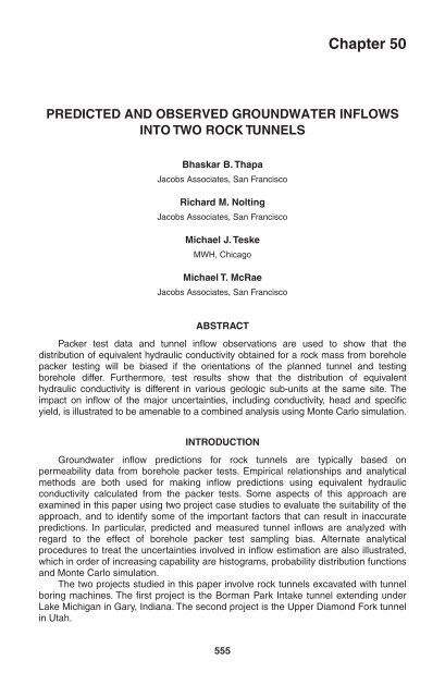
Chapter 50<br />
PREDICTED AND OBSERVED GROUNDWATER INFLOWS<br />
INTO TWO ROCK TUNNELS<br />
Bhaskar B. Thapa<br />
Jacobs Associates, San Francisco<br />
Richard M. Nolting<br />
Jacobs Associates, San Francisco<br />
Michael J. Teske<br />
MWH, Chicago<br />
Michael T. McRae<br />
Jacobs Associates, San Francisco<br />
ABSTRACT<br />
Packer test data <strong>and</strong> tunnel inflow observations are used to show that the<br />
distribution of equivalent hydraulic conductivity obtained for a rock mass from borehole<br />
packer testing will be biased if the orientations of the planned tunnel <strong>and</strong> testing<br />
borehole differ. Furthermore, test results show that the distribution of equivalent<br />
hydraulic conductivity is different in various geologic sub-units at the same site. The<br />
impact on inflow of the major uncertainties, including conductivity, head <strong>and</strong> specific<br />
yield, is illustrated to be amenable to a combined analysis using Monte Carlo simulation.<br />
INTRODUCTION<br />
<strong>Groundwater</strong> inflow predictions for rock tunnels are typically based on<br />
permeability data from borehole packer tests. Empirical relationships <strong>and</strong> analytical<br />
methods are both used for making inflow predictions using equivalent hydraulic<br />
conductivity calculated from the packer tests. Some aspects of this approach are<br />
examined in this paper using two project case studies to evaluate the suitability of the<br />
approach, <strong>and</strong> to identify some of the important factors that can result in inaccurate<br />
predictions. In particular, predicted <strong>and</strong> measured tunnel inflows are analyzed with<br />
regard to the effect of borehole packer test sampling bias. Alternate analytical<br />
procedures to treat the uncertainties involved in inflow estimation are also illustrated,<br />
which in order of increasing capability are histograms, probability distribution functions<br />
<strong>and</strong> Monte Carlo simulation.<br />
The two projects studied in this paper involve rock tunnels excavated with tunnel<br />
boring machines. The first project is the Borman Park Intake tunnel extending under<br />
Lake Michigan in Gary, Indiana. The second project is the Upper Diamond Fork tunnel<br />
in Utah.<br />
555
556 2003 RETC PROCEEDINGS<br />
BORMAN PARK TUNNEL<br />
Project Description <strong>and</strong> Ground Conditions<br />
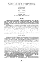
The Borman Park Intake Improvement Project includes a new Lake Michigan Raw<br />
Water Intake Tunnel System to replace the existing one. The new intake tunnel system,<br />
shown in Figure 1, is approximately 15,835 feet long, 11.5 feet in excavated diameter,<br />
<strong>and</strong> was excavated in rock using a Tunnel Boring Machine at an average depth of 216<br />
feet below the ground surface. A 96-inch-diameter, steel-lined, drilled shaft,<br />
approximately 136-feet deep, has been constructed in Lake Michigan to connect the<br />
tunnel to a new timber intake crib on the lakebed.<br />
Stratigraphy at the Borman Park Tunnel site consists of 85 to 125 feet of s<strong>and</strong> <strong>and</strong><br />
clay overburden overlying bedrock. The s<strong>and</strong> is loose to medium dense <strong>and</strong> the clay<br />
grades from a soft to hard consistency with depth. Bedrock consists of Devonian<br />
carbonates <strong>and</strong> interbedded shales overlying Silurian dolomite. The contact between<br />
the Silurian <strong>and</strong> Devonian is an unconformity (erosion surface) <strong>and</strong> frequently contains<br />
isolated zones of soft green clay <strong>and</strong> rubbly rock, two to three feet thick. The tunnel is<br />
located entirely in the Silurian dolomite a minimum of 22 feet below the estimated<br />
Devonian—Silurian contact zone. The measured piezometric level in the rock is 4 to<br />
5 feet below the ground surface.<br />
Expected Distribution of Hydraulic Conductivity<br />
Water pressure tests were conducted in four boreholes along the tunnel alignment<br />
following the method described in the Ground Water Manual (Ground Water Manual,<br />
1981). Each borehole was tested over six to eleven intervals between 11.5 feet to<br />
12.5 feet in length. A total of 33 tests were conducted with pressures ranging from 33<br />
to 105 psi.<br />
The equivalent hydraulic conductivity of the rock was computed from test results<br />
using the equation for radial flow as previously described by Raymer (2001). Test<br />
results were interpreted first as representing the entire range of conductivities the<br />
tunnel is expected to encounter, <strong>and</strong> second as a partial sample from a population of<br />
conductivities the tunnel will encounter. The second approach is taken since test<br />
results at high conductivities can be affected by limitations of the testing equipment<br />
rather than the properties of the rock mass. The choice of a particular distribution<br />
depends on the observations—here a positive skew in the data led to the selection of a<br />
lognormal distribution.<br />
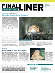
The measured conductivities summarized in the histogram of Figure 2 suggest<br />
the equivalent hydraulic conductivity will range between below 10 –6 cm/s to 3 × 10 –3<br />
cm/s, with a median value of 1 × 10 –5 cm/s.<br />
Interpretation of packer test results using probability distribution functions was<br />
done by estimating log-normal distribution parameters using the packer test results<br />
<strong>and</strong> computing cumulative frequencies in the hydraulic conductivity working ranges<br />
used for inflow estimation. Figure 2 shows the histogram derived from the lognormal<br />
distribution. Comparison with the histogram from direct packer test derived data shows<br />
two significant differences at the median <strong>and</strong> high values—the direct data is<br />
concentrated at a relatively low median while the lognormal distribution function has a<br />
high value tail that extends the range of expected conductivity values the tunnel can<br />
encounter.
GROUNDWATER INFLOWS INTO TWO ROCK TUNNELS 557<br />
Figure 1. Plan <strong>and</strong> profile of Borman Park intake tunnel
558 2003 RETC PROCEEDINGS<br />
0.45<br />
0.40<br />
0.35<br />
0.30<br />
Relative Frequency<br />
0.25<br />
0.20<br />
0.15<br />
0.10<br />
0.05<br />
0.00<br />
1.00E-06 3.00E-06 1.00E-05 3.00E-05 1.00E-04 3.00E-04 1.00E-03 3.00E-03 1.00E-02<br />
Hydraulic Conductivity (cm/sec)<br />
Log Normal Distribution<br />
Histogram of Recorded Measurements<br />
Figure 2.<br />
Histograms of Borman Park water pressure test results<br />
Empirical Predictions<br />
Inflow predictions were made using the procedure described by Heuer (1995) <strong>and</strong><br />
augmented by Raymer (2001). One inflow estimate was made by using the packer test<br />
data directly with Heuer’s procedure <strong>and</strong> a second estimate was made using the<br />
packer test data to estimate percentages of tunnel crossing a log-normally distributed<br />
hydraulic conductivity population. The head ranges between 184 to 201 feet, <strong>and</strong> a low<br />
<strong>and</strong> high inflow estimate was made for either extreme.<br />
Inflow predictions from the two methods are presented in Figure 3, which shows<br />
inflow for each conductivity interval, <strong>and</strong> a cumulative inflow obtained by summing<br />
inflows from each interval (from lowest to highest conductivity). Both methods indicate<br />
that the inflow will be dominated by relatively high hydraulic conductivities. The<br />
analysis shows 75% (histogram) <strong>and</strong> 65% (lognormal) of total inflow is due to zones<br />
with hydraulic conductivities above 1 × 10 –3 cm/sec. The high tail end conductivities<br />
incorporated <strong>into</strong> the lognormal analysis leads to a 15% higher total inflow estimate of<br />
698 gpm compared to the histogram based estimate of 590 gpm.<br />
Inflow Observations<br />
Tunnel inflows were mapped between 3 days to a week after tunnel excavation,<br />
<strong>and</strong> about 300 feet behind the TBM heading position. <strong>Inflows</strong> measured during this<br />
time <strong>and</strong> at this distance from the tunnel face were lower than heading inflows, <strong>and</strong><br />
represent sources that provided sustained flow after many transient inflow sources had<br />
dried up. The observations are assumed to represent an approximation of the<br />
distribution of long-term steady state inflows. Actual steady state inflow quantities are<br />
expected to be somewhat lower than mapped due to drainage of fractures.<br />
The inflows mapped over a mile of the tunnel were summed over 100-foot intervals<br />
<strong>and</strong> converted to inflow per unit length. The resulting data was compiled <strong>into</strong> a histogram<br />
<strong>and</strong> is shown in Figure 4 along with predicted inflow. <strong>Observed</strong> inflows have a different<br />
distribution form <strong>and</strong> higher mean than the predictive histograms, as seen in Figure 4.<br />
The mean value of hydraulic conductivity from packer testing data was 5.5 × 10 –5 cm/sec<br />
while the mean value implied by the observed inflows is 2 × 10 –4 cm/sec. The
GROUNDWATER INFLOWS INTO TWO ROCK TUNNELS 559<br />
800.00<br />
700.00<br />
600.00<br />
Inflow (gpm)<br />
500.00<br />
400.00<br />
300.00<br />
200.00<br />
100.00<br />
0.00<br />
1.00E-06 3.00E-06 1.00E-05 3.00E-05 1.00E-04 3.00E-04 1.00E-03 3.00E-03 1.00E-02<br />
Hydraulic Conductivity (cm/sec)<br />
Figure 3.<br />
Total Inflow, Measured Conductivity<br />
Cumulative Inflow, Measured Conductivity<br />
Distribution of predicted total tunnel inflow<br />
Total Inflow, Log Normal Conductivity<br />
Cumulative Inflow, Lognormal Conductivity<br />
0.50<br />
0.45<br />
0.40<br />
Relative Frequency<br />
0.35<br />
0.30<br />
0.25<br />
0.20<br />
0.15<br />
0.10<br />
0.05<br />
0.00<br />
0.05 0.09 0.31 0.94 3.07 9.45 30.71 94.49 141.74<br />
Inflow (gpm) Per 100 Foot of Tunnel Length<br />
Measured Conductivity <strong>Predicted</strong> Inflow Per 100 ft<br />
Lognormal Conductivity <strong>Predicted</strong> Inflow Per 100 ft<br />
<strong>Observed</strong> <strong>Inflows</strong><br />
Figure 4.<br />
<strong>Predicted</strong> <strong>and</strong> observed inflow per 100-ft tunnel length<br />
encountered distribution of conductivities is significantly different from the distribution<br />
suggested by the packer testing, <strong>and</strong> the assumed lognormal distribution function.<br />
Evaluation of Results<br />
The use of packer test data from vertical boreholes as a sample of conductivities<br />
along a horizontal rock tunnel implies the conductivities are isotropic. Thus sampling<br />
rock quality, or more specifically fracture density, along any direction is assumed to<br />
capture the actual distribution in conductivity. This assumption was examined using<br />
correlation plots between measured conductivity or inflow, <strong>and</strong> fracture density.
560 2003 RETC PROCEEDINGS<br />
12<br />
10<br />
Number of fractures per 100 ft<br />
8<br />
6<br />
4<br />
2<br />
0<br />
0 5 10 15 20 25<br />
Inflow Per 100 Foot of Tunnel (gpm/100ft)<br />
Figure 5. Correlation between inflow <strong>and</strong> discontinuity density<br />
The correlation between inflow <strong>and</strong> fracture density was investigated by plotting<br />
observations of these two parameters along a mile of tunnel length, as shown in<br />
Figure 5. No correlation is evident in the plot, i.e. a fracture swarm did not lead to<br />
higher inflows <strong>and</strong> visa versa. Similarly no correlation is seen in the plot of measured<br />
hydraulic conductivities <strong>and</strong> RQD shown in Figure 6. These observations suggest that<br />
rock quality, represented by fracture density alone, does not control conductivity or<br />
inflow. Other factors affecting the packer test results such as fracture aperture <strong>and</strong><br />
infilling will be represented in sampled distribution of conductivities, but the effect of<br />
fracture orientation may not be adequately represented. More specifically, since the<br />
fractures encountered by a borehole will vary with its orientation, a sampling bias is<br />
introduced when the borehole orientation differs from that of the planned tunnel. A<br />
biased borehole will encounter different fractures, with different inter-connectivity<br />
patterns than one that is not biased. Thus if conductivity in the rock mass is dominated<br />
by a particular joint set that is under represented due to orientation sampling bias, the<br />
measured distribution of conductivity will not be representative. A simple illustration of<br />
this is provided by a vertical borehole at a site dominated by near vertical fractures,<br />
which are missed by the borehole but intersected by a horizontal tunnel. Clearly,<br />
orientation sampling bias is minimized when the borehole used for packer testing is<br />
close to the planned tunnel orientation.<br />
Measured <strong>and</strong> predicted inflows <strong>into</strong> the Borman Park Tunnel as a function of<br />
tunnel heading station are shown in Figure 7. The measured sustained inflow agrees<br />
with the upper bound prediction based on measured inflow distribution below Station<br />
6000, as would be expected since this is where the inflow distribution observations<br />
were made. The rate of increase of the measured sustained inflow between Stations<br />
6000 <strong>and</strong> 11000 is less than that from packer test predictions. This may have been<br />
related to the relatively higher occurrence, <strong>and</strong> consistency, of clay filled Silurian-<br />
Devonian contact zones along this portion of the alignment compared to other
GROUNDWATER INFLOWS INTO TWO ROCK TUNNELS 561<br />
100<br />
90<br />
80<br />
RQD %<br />
70<br />
60<br />
50<br />
1.00E-08 1.00E-07 1.00E-06 1.00E-05 1.00E-04 1.00E-03 1.00E-02 1.00E-01 1.00E+00<br />
Equivalent Hydraulic Conductivity (cm/sec)<br />
Figure 6.<br />
Correlation between equivalent hydraulic conductivity <strong>and</strong> RQD<br />
1600<br />
1400<br />
1200<br />
Sustained<br />
Inflow (gpm)<br />
1000<br />
800<br />
600<br />
400<br />
200<br />
0<br />
0 2000 4000 6000 8000 10000 12000 14000 16000<br />
Tunnel Station<br />
Measured Sustained Inflow<br />
Prediction Based on Measured Inflow Distribution<br />
Prediction Based on Packer Test Histogram<br />
Figure 7.<br />
Measured average weekly inflows at Borman Park
562 2003 RETC PROCEEDINGS<br />
locations. The relatively close agreement between the packer test predictions<br />
(600 gpm) <strong>and</strong> the measured sustained inflows (800 gpm) at the final tunnel stationing<br />
is believed to be partly due to the occurrence of this low conductivity material.<br />
UPPER DIAMOND FORK TUNNEL<br />
Project Description<br />
The Upper Diamond Fork Tunnel, under construction in Utah County, Utah, is part<br />
of a tunnel <strong>and</strong> pipeline system to carry raw water from the Wasatch Mountains to the<br />
valley south of Salt Lake City. The Central Utah Water Conservancy District is project<br />
owner, <strong>and</strong> a joint venture of Obayashi <strong>and</strong> W.W. Clyde is the constructor. The tunnel,<br />
originally designed to be 22,800 feet long, has an excavated diameter of 12.5 feet <strong>and</strong><br />
a gradient of 0.175 percent. As described in the paper by Wimmer <strong>and</strong> Gowring<br />
(2003), tunnel excavation was stopped some 2600 feet short of the end station at the<br />
inlet shaft due to <strong>into</strong>lerably high concentrations of hydrogen sulfide gas. Since then, in<br />
order to bypass the zone of gassy ground, the tunnel has been plugged <strong>and</strong> a shaft<br />
constructed close to the tunnel crossing of Diamond Fork Creek. To complete the<br />
bypass, a second phase of the project involves constructing a tunnel, approximately<br />
one mile long that connects to a pipeline along Upper Diamond Fork Creek. This<br />
pipeline terminates at a flow control structure which discharges <strong>into</strong> a shaft that<br />
connects to the original tunnel.<br />
Geology <strong>and</strong> <strong>Groundwater</strong><br />
Figure 8 is a general geologic <strong>and</strong> topographic profile along the Upper Diamond<br />
Fork Tunnel between the west portal <strong>and</strong> the Sixth Water shaft. As depicted on the<br />
profile, the tunnel extends through the upper, middle, <strong>and</strong> lower members of the Red<br />
Narrows Conglomerate, which are moderately folded <strong>and</strong> faulted Cretaceous to<br />
Tertiary-age sedimentary rocks. These formations are comprised mainly of<br />
conglomerate, siltstone, <strong>and</strong> s<strong>and</strong>stone. Underlying the Red Narrows Conglomerate,<br />
<strong>and</strong> separated by a regional unconformity, are Jurassic rocks. Hot springs that occur in<br />
Diamond Fork Canyon are considered to be associated with faulting that developed in<br />
the Jurassic rocks.<br />
A total of 84 borehole packer permeability tests were conducted in the Upper,<br />
Middle, <strong>and</strong> Lower members of the Red Narrows Conglomerate <strong>and</strong> these data<br />
provided the principal input to the analysis of groundwater inflow for the Diamond<br />
Fork Tunnel. Relative frequency distributions of hydraulic conductivity were<br />
developed for each of the members. As shown in Figure 9, the probability distribution<br />
for each member is distinct, especially for the Middle <strong>and</strong> Lower members in<br />
comparison to the Upper member. This variation suggests that hydraulic conductivity<br />
distributions for geologic units cannot be assigned, a priori, a particular form. Also,<br />
combining the distributions would have produced a bi-modal distribution with<br />
different parameters Figure 9 suggests packer-testing data should be considered<br />
separately by geologic unit.<br />
Analysis <strong>and</strong> Prediction of <strong>Groundwater</strong> Inflow<br />
<strong>Groundwater</strong> inflows were predicted using a statistical analysis developed by<br />
Golder Associates (GBR, 2001). The method utilizes Monte Carlo simulation to<br />
develop statistical distributions of inflow by sampling distributions of the major sources<br />
of uncertainity, <strong>and</strong> combining them using an inflow function. Results were used to
GROUNDWATER INFLOWS INTO TWO ROCK TUNNELS 563<br />
Figure 8.<br />
General geologic <strong>and</strong> topographic profile along Upper Diamond Fork Tunnel<br />
develop estimates of both instantaneous inflows at the tunnel heading <strong>and</strong> sustained<br />
inflows measured at the tunnel portal. Results of the analysis indicate: (1) a maximum<br />
sustained groundwater inflow of 1,500 gallons per minute (gpm) <strong>into</strong> the tunnel, as<br />
measured at the west portal, <strong>and</strong> (2) a maximum instantaneous groundwater inflow of<br />
1,500 gpm, as defined for a 100-foot heading length. In the analysis, the statistical<br />
approach simulated: initial heading inflow, eventual decline of heading inflow, <strong>and</strong><br />
contributions of individual inflows to the sustained inflow over the length of the tunnel.<br />
Also, the statistical approach modeled a wide range of possible inflow interactions,<br />
such as the occurrence of a large heading inflow at a time when all previous inflows<br />
were insignificant, or multiple heading inflows that collectively were larger than any<br />
single inflow.<br />
To apply the analysis, assumptions were necessary regarding the probability of<br />
encountering water-bearing features, including unknown fractures, or faults, <strong>and</strong><br />
known faults. The type <strong>and</strong> frequency of faulting was based on field mapping along the<br />
project alignment. In addition to the occurrence of fractures <strong>and</strong> faults <strong>and</strong> their<br />
equivalent hydraulic conductivities, based on the results of borehole testing,<br />
assumptions were made regarding distributions of groundwater head <strong>and</strong> specific yield<br />
of fractures. <strong>Groundwater</strong> heads were given a triangular probability distribution <strong>and</strong><br />
assumed to range from a maximum value at the ground surface to a likely value at the<br />
expected groundwater table, located on the basis of borehole information <strong>and</strong><br />
elevations of springs <strong>and</strong> Diamond Fork Creek. A minimum value was taken as half the<br />
likely value. Specific yield, which mainly dictates how fast an inflow declines from the<br />
instantaneous value, was also given a triangular distribution. Typical values for an<br />
unconfined, water table aquifer range from 0.3 for s<strong>and</strong> <strong>and</strong> gravel to 0.02 for clay,<br />
whereas a confined aquifer has a typical value of 0.005. For the analysis, assumed<br />
maximum, likely, <strong>and</strong> minimum values for fractures were 0.05, 0.01, <strong>and</strong> 0.001,<br />
respectively, <strong>and</strong> for faults these values were 0.25, 0.1, <strong>and</strong> 0.03, respectively.
564 2003 RETC PROCEEDINGS<br />
Figure 9.<br />
Hydraulic conductivity distributions at Upper Diamond Fork Tunnel<br />
<strong>Predicted</strong> Instantaneous Inflow<br />
Statistical simulations were conducted by dividing the tunnel <strong>into</strong> 228, 100-foot<br />
long sections, each of which was assigned an equivalent hydraulic conductivity<br />
depending on the geologic formation in that section. The probability of encountering<br />
known <strong>and</strong> unknown water-bearing features in each section, as well as their applicable<br />
conductivity probability distribution was incorporated. The distribution of specific yield,<br />
as given above, was also assigned, as was the groundwater head at the section. With<br />
these parameters assigned, equations developed by Goodman et al. (1965) were used<br />
to calculate the instantaneous heading inflow <strong>and</strong> subsequent reduction with time.<br />
Monte Carlo simulations of 1,000 runs were used to develop the statistical variation of<br />
tunnel inflows.<br />
To develop instantaneous inflows, the calculated flow from each run was retained,<br />
<strong>and</strong> after all simulation runs had been completed, the range, mean, <strong>and</strong> median
GROUNDWATER INFLOWS INTO TWO ROCK TUNNELS 565<br />
Figure 10.<br />
Instantaneous flow along Upper Diamond Fork Tunnel<br />
values, as well as st<strong>and</strong>ard deviation <strong>and</strong> the main percentiles in each 100-foot tunnel<br />
section were recorded. Figure 10 shows three curves corresponding to the median<br />
(50th percentile), the 90th percentile, <strong>and</strong> the maximum value. The horizontal axis on<br />
this figure corresponds to the tunnel stationing, with the west portal on the right side<br />
<strong>and</strong> shaft at Sixth Water Creek on the left. The right vertical axis shows the<br />
instantaneous inflow in logarithmic scale. For reference purposes, the figure also<br />
shows the ground profile <strong>and</strong> the expected groundwater table, with the corresponding<br />
scale for height on the left. A baseline value of 1500 gpm bounds the largest value of<br />
the 90th percentile of about 1,400 gpm, <strong>and</strong> although not depicted, the largest value of<br />
the mean-plus-one st<strong>and</strong>ard deviation of about 1,100 gpm.<br />
<strong>Predicted</strong> Sustained Inflow<br />
The sustained inflow represents the total groundwater inflow to the tunnel, as<br />
measured at the portal. During tunnel excavation, the sustained water flow from the<br />
west portal was expected to fluctuate as new water-bearing features were<br />
encountered <strong>and</strong> previously encountered features dried up. The fluctuation in the<br />
sustained flow was calculated by combining individual flows in all 100-foot sections<br />
that had been excavated up to that moment. The analysis assumed a uniform<br />
excavation rate of 100 feet per day for a 7-day week. Figure 11 presents the sustained<br />
flow calculated from the 1,000-run statistical simulations. Tunnel stationing is shown on<br />
the horizontal axis, <strong>and</strong> sustained flow is given on the right h<strong>and</strong> vertical axis. Note<br />
that, unlike Figure 10, the sustained flow is plotted in natural scale. The three curves<br />
on the figure correspond to the minimum, mean, <strong>and</strong> maximum sustained flows. The<br />
largest average sustained flow is about 1,500 gpm. Although the sustained <strong>and</strong> the<br />
instantaneous heading flow have been assigned the same numerical value of<br />
1,500 gpm, this is a coincidence, as the two flow quantities were calculated separately.
566 2003 RETC PROCEEDINGS<br />
Figure 11.<br />
Sustained flow during excavation of Upper Diamond Fork Tunnel<br />
<strong>Observed</strong> Instantaneous Inflow<br />
<strong>Groundwater</strong> inflows observed in the tunnel during construction consisted<br />
predominately of inflows from discontinuities such as joints <strong>and</strong> faults. Estimates of<br />
inflow quantities were recorded soon after encountering the inflow, however, because<br />
the initial inflows were typically observed in areas of the tunnel behind the trailing gear<br />
of the TBM, estimates were often below the actual instantaneous inflow.<br />
Between the west portal <strong>and</strong> Station 74+50, recorded individual inflows ranged<br />
from drips <strong>and</strong> seeps to point sources up to at least 100 gpm,. These recorded inflows<br />
were used to make a plot of maximum 100-foot heading inflows, as shown on<br />
Figure 10. The highest observed 100-foot “heading” inflows were 490 gpm, centered<br />
on Station 98+00, <strong>and</strong> 350 gpm, near the creek crossing at Station 110+00. Few 100-<br />
foot tunnel segments had inflows greater than about 50 gpm. The major exception was<br />
at fault F-4 (see Figure 8) where an instantaneous inflow of about 3000 gpm was<br />
encountered. In general, not only did the tunnel encounter more water-bearing<br />
fractures east of the Upper Diamond Fork crossing, but the factures intersected were<br />
on average much more productive than those encountered before the creek crossing.<br />
<strong>Observed</strong> Sustained Inflow<br />
As seen on Figure 11, before the Upper Diamond Fork crossing, the observed<br />
sustained inflow fell below the low curve of the predicted inflow. However, past the<br />
creek crossing, the flow increased rapidly <strong>and</strong> eventually exceeded the maximum<br />
predicted value. Note that at Station 72+00, the baseline analysis had predicted a<br />
median inflow of about 600 gpm <strong>and</strong> a maximum inflow of about 1,500 gpm, as<br />
compared to the 2,800 gpm actually measured.<br />
The observed instantaneous <strong>and</strong> sustained inflows were less than predicted<br />
before the creek crossing <strong>and</strong> greater after the creek crossing. An apparent<br />
explanation for this change is that the hydraulic conductivity of the water-bearing<br />
features east of the creek crossing exceeded the highest value measured in the<br />
borehole packer tests. An indication of such a condition was the higher frequency of<br />
observed inflows from open fractures, which were perceived to have wider apertures in
GROUNDWATER INFLOWS INTO TWO ROCK TUNNELS 567<br />
this portion of the tunnel. Such open features were not observed either in exploratory<br />
boreholes or in outcrops during site investigation, nor were they prevalent in the tunnel<br />
up to the creek crossing. Another contributing factor is that the groundwater head is<br />
about 2 times higher after the creek crossing than before. It has been hypothesized<br />
that the head was, at least locally, much higher due to communication with a deep,<br />
confined aquifer. This possibility is supported in part by the fact that the groundwater<br />
temperatures in the tunnel was several degrees above the normal geothermal gradient<br />
past the creek crossing whereas the groundwater temperatures were within the normal<br />
gradient prior to the creek crossing<br />
CONCLUSIONS<br />
Packer testing data at the Borman Park tunnel produced a distribution of hydraulic<br />
conductivity different from the distribution implied by measurements during<br />
construction. The discrepancy is believed due to a fracture orientation sampling bias<br />
introduced by the use of vertical boreholes to represent a horizontal tunnel. Packer<br />
testing in boreholes closer to the planned tunnel orientation will minimize orientation<br />
sampling bias.<br />
Packer test results at the Upper Diamond Fork tunnel showed distributions of<br />
hydraulic conductivity that vary significantly by geologic unit. Furthermore the data<br />
showed that hydraulic conductivity distributions cannot be assigned a particular form<br />
(i.e., log normal) a priori. In the area east of Upper Diamond Fork the observed<br />
hydraulic conductivity also appears to have been significantly higher, than as sampled<br />
by the packer measurements. Water-bearing fractures <strong>and</strong> faults encountered during<br />
tunneling were typically near-vertical, indicating these open features were not as<br />
readily sampled by vertical borings. However, it is hypothesized that a higher than<br />
expected groundwater head was likely the other significant factor in producing the<br />
higher inflows. West of the creek, it appears that a lower than anticipated head is the<br />
primary factor in explaining the relatively low inflows observed in that portion of the<br />
tunnel. While sampling orientation bias <strong>and</strong> lack of data on groundwater head limited<br />
satisfactory characterization of the uncertainties involved in inflow prediction on this<br />
project, the Monte Carlo simulation method proved to be a useful technique for<br />
evaluating the combined effect of the factors, <strong>and</strong> the uncertainties associated with<br />
these factors, on predicted inflow.<br />
REFERENCES<br />
Goodman, R.E., D.G. Moye, A. Van Schalkwyk, <strong>and</strong> I. Jav<strong>and</strong>el, “<strong>Groundwater</strong> <strong>Inflows</strong><br />
During Tunnel Driving,” Engineering Geology, v. 1, no. 1, p. 39–56, 1965.<br />
Heuer, R. E., “Estimating <strong>Rock</strong> Tunnel Water Inflow,” RETC Proceedings, Chapter 3,<br />
p. 41–60, 1995.<br />
Raymer, J.H., “Predicting <strong>Groundwater</strong> Inflow Into Hard-<strong>Rock</strong> <strong>Tunnels</strong>: Estimating the<br />
High-End of the Permeability Distribution,” RETC Proceedings, Chapter 83,<br />
p. 1027–1038, 2001.<br />
Geotechnical Baseline Report, Upper Diamond Fork Project, Report to Central Utah<br />
Water Conservancy District, by Jacobs Associates <strong>and</strong> Golder Associates, 2001.<br />
Ground Water Manual, Water <strong>and</strong> Power Resources Service, US Department of<br />
Interior, Revised Reprint, John Wiley <strong>and</strong> Sons, 1981.<br />
Wimmer, H. L. <strong>and</strong> M. Gowring, “The Upper Diamond Fork Project,” RETC<br />
Proceedings, 2003.