3D Simulations for Cold Pilgering Process by Explicit FEM
3D Simulations for Cold Pilgering Process by Explicit FEM
3D Simulations for Cold Pilgering Process by Explicit FEM

Create successful ePaper yourself
Turn your PDF publications into a flip-book with our unique Google optimized e-Paper software.
X International Conference on Computational Plasticity<br />
COMPLAS X<br />
E. Oñate and D. R. J. Owen (Eds)<br />
© CIMNE, Barcelona, 2009<br />
<strong>3D</strong> SIMULATIONS FOR COLD PILGERING PROCESS<br />
BY EXPLICIT <strong>FEM</strong><br />
H. Nakanishi * , S. Toyoshima ** , M. Harada ** and A. Honda ***<br />
* Kobe City College of Technology<br />
Gakuenhigashimachi 8-3, Kobe, 761-2194, Japan<br />
e-mail: nakanisi@kobe-kosen.ac.jp, web page: http://www.kobe-kosen.ac.jp<br />
** Kobelco Research Institute, Inc<br />
Amagasaki Hyogo, Japan<br />
e-mail: toyoshima.shiro@kki.kobelco.com, web page: http://www.kobelcokaken.co.jp<br />
*** Zirco Products Co.<br />
Chofuminatomachi, Shimonoseki, Japan<br />
e-mail: honda@zpc.co.jp<br />
Key words: <strong>Cold</strong> <strong>Pilgering</strong>, Simulation, Ls-Dyna, Roller-Dies, Tube, Mandrel, Elongation<br />
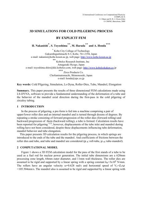
Summary. This paper presents the results of three dimensional <strong>FEM</strong> calculations made using<br />
LS-DYNA, software to provide a fundamental understanding of the de<strong>for</strong>mation of a tube and<br />
the behavior of the mandrel axial direction during the first-pass in the cold pilgering of<br />
zircaloy tubing.<br />
1 INTRODUCTION<br />
In the process of pilgering, a pre-<strong>for</strong>m is fed into a machine comprising a pair of<br />
upper/lower roller dies and an internal mandrel and is turned through dozens of degrees. By<br />
repeating a stroke consisting of <strong>for</strong>ward progression of the roller dies (<strong>for</strong>ward rolling) and<br />
backward progression of them (backward rolling), a tube is <strong>for</strong>med. Calculation results have<br />
been reported <strong>for</strong> pilgering 1),2) , however, displacements of the tube inlet and mandrel during<br />
rolling have not been considered, despite these displacements influencing tube de<strong>for</strong>mation,<br />
mandrel behavior and tube elongation.<br />
This paper presents <strong>3D</strong> calculation results <strong>for</strong> the pilgering process, in which springs are<br />
introduced to the ends of the tube and the mandrel. And coefficients of frictions between the<br />
roller dies and tube, and tube and mandrel are considered ( R : roll-tube, M : tube-mandrel).<br />
2 COMPUTATIONAL MODEL<br />
Figure 1 shows a <strong>3D</strong> <strong>FEM</strong> calculation model <strong>for</strong> the pass of the first stands of a tube to be<br />
used as a fuel rod <strong>for</strong> nuclear power generation. The initial tube dimensions are a 620mm<br />
processing zone length, 64mm outer diameter, and 11mm wall thickness. The roller dies are<br />
assumed to be rigid and supported <strong>by</strong> a linear spring with a spring constant k R =3x10 6 N/mm.<br />
The rollers have an angular velocity ω=0.628 rad/s and horizontal speed of V x =Z P <br />
=105.504mm/s. The mandrel also is assumed to be rigid and supported <strong>by</strong> a linear spring with
H. Nakanishi, S. Toyoshima, M. Harada and A. Honda.<br />
a spring constant k M =38kN/mm. The tube is assumed to have isotropic elastoplasticity and be<br />
supported <strong>by</strong> a nonlinear spring with spring constant k T that corresponds to the clamp support<br />
(elasticity spring constant of 4.75kN/mm, plasticity spring constant of 23.75N/mm, and yield<br />
axial <strong>for</strong>ce of 600N). Three curves <strong>for</strong> the tool shape (R R (x): the evolution of the upper roller<br />
groove at y=0, R M (x): the mandrel radius, and Z P : the pinion position) are shown in Figure 2.<br />
For the initial condition of the calculation of the first pass, the outer shape of the tube is set to<br />
the <strong>for</strong>m of the roller groove, and the inner shape set to that of the mandrel. In the case of<br />
advancing calculations, the shape of the tube is used with the result of calculations. The<br />
thickness of the tube is divided in two, and the length of the rolling potion of the tube is<br />
divided into 400 segments. The number of tube elements is 69120. The stress strain curve of<br />
the zirconium material of the tube is shown in Figure 3.<br />
Figure 1: Computation model<br />
<br />
R R /RRmax , R M /R R max , Z P /R R max<br />
<br />
<br />
<br />
<br />
R<br />
M /R R max<br />
R<br />
R /R R max<br />
Z<br />
P /R R max<br />
<br />
<br />
X / L<br />
Figure 2: Roller groove at y=0 R R (x), mandrel radius R M (x) and pinion position Z P<br />
2
H. Nakanishi, S. Toyoshima, M. Harada and A. Honda.<br />
<br />
<br />
<br />
<br />
<br />
<br />
<br />
<br />
<br />
<br />
<br />
Figure 3: Sress-strain curve of tube zircaloy<br />
3 EFFECTS OF FRICTION ON THE CONTACT SURFACE<br />
We first calculated the de<strong>for</strong>mation behavior during one stroke <strong>for</strong> 1/4 models assuming<br />
symmetry of the entire apparatus comprising roller dies, tube and mandrel. <strong>Pilgering</strong> was<br />
simulated using the parameters of the initial tube shape, the support spring of the mandrel, the<br />
roller dies and the tube, and coefficients of friction between the roller dies and tube, and tube<br />
and mandrel. The effects of these parameters on tube elongation were then examined and the<br />
calculation results were compared with measurements taken using the laser equipment in an<br />
industrial pilger mill. Tube elongation E is defined as E=U O -U I (U O : the tube-outlet<br />
displacement, U I : the tube-inlet displacement). The results show that the transmitted axial<br />
<strong>for</strong>ce and the displacement of the tube and mandrel changed with the coefficients of friction.<br />
Calculation results obtained <strong>for</strong> the elongation using coefficients of friction such as µ R =0.075<br />
and µ M =0.03 show good agreement with measurement results. In the <strong>for</strong>ward stroke the<br />
difference among elongations <strong>for</strong> each case of R and M seems to be small, and the tube<br />
elongation is large <strong>for</strong> the backward stroke when µ R is large and µ M is small.<br />
<br />
<br />
<br />
<br />
<br />
<br />
<br />
<br />
<br />
<br />
<br />
<br />
<br />
<br />
<br />
<br />
<br />
µ R µ R<br />
<br />
<br />
µ M <br />
µ <br />
M<br />
<br />
<br />
(a) Forward stroke (b) Backward stroke<br />
Figure 4: Tube elongation <strong>by</strong> using the 1/4 model<br />
<br />
<br />
<br />
3
H. Nakanishi, S. Toyoshima, M. Harada and A. Honda.<br />
4 SIMULATION OF THE PILGERING PROCESS<br />
We next simulated pilgering using a full <strong>3D</strong> model in which the values of R and M were<br />
set as 0.075 and 0.03 respectively from the previous results. Feeding (1.2mm), rotating<br />
(60degrees) and <strong>for</strong>ward/backward rolling were carried out three times. Figure 5 shows the<br />
displacements of the tube ends and mandrel after the three cycles. The roller moves from x=0<br />
to approximately x=612mm in the <strong>for</strong>ward rolling, and returns from x=612mm to x=0 in the<br />
backward rolling. The elongation of the tube is from 0 to 3.3mm and from 3.3mm to<br />
approximately 6mm <strong>for</strong> the <strong>for</strong>ward and backward rollings respectively. The calculated<br />
elongation of the tube is almost the measured value, but the displacement curve <strong>for</strong> the tube<br />
inlet seems not to coincide with that measured, particularly <strong>for</strong> the <strong>for</strong>ward stroke.<br />
In addition, the spring constant of the tube support influenced the displacement of the inlet<br />
end of the tube, but the influence on the tube elongation was small.<br />
Disp. (mm)<br />
8<br />
6<br />
4<br />
2<br />
0<br />
-2<br />
-4<br />
0 100 200 300 400 500 600<br />
Roll Position (mm)<br />
Figure 5: Displacements of the tube ends and mandrel, and tube elongation<br />
5 CONCLUSIONS<br />
Mandrel<br />
Tube-inlet<br />
Tube-outlet<br />
Elongation<br />
The effects of parameters on the tube elongation were calculated and the elongations were<br />
compared with the measured value. From our results, it is clear that the transmitted axial <strong>for</strong>ce<br />
and displacements of the tube and the mandrel changed with the coefficients of friction. The<br />
calculated elongation <strong>for</strong> coefficients of friction such as µ R =0.075 and µ M =0.03 was in good<br />
agreement with the measured value. The computational models of the support ends of the tube<br />
and the mandrel are uncertain. It is thus necessary to clarify and model the support<br />
mechanism. After this we will attempt to obtain calculation results <strong>for</strong> the displacement curve<br />
of the tube that closely match measurements.<br />
REFERENCES<br />
[1] M. Harada, A. Honda and S. Toyoshima, “Simulation of cold pilgering <strong>Process</strong> <strong>by</strong> a Generalized Plane<br />
Strain <strong>FEM</strong>”, J. of ASTM International, 2, 3, 233-247 (2005)<br />
[2] S. Mulot, A. Hacquin, P. Montmitonnet and J.-L. Aubin, “A fully <strong>3D</strong> finite element simulation of cold<br />
pilgering”, J. of Materials <strong>Process</strong>ing Technology, 60, 505-512 (1996).<br />
4