Allgemeine Hinweise: Montageanleitung Mercedes ML/GL W/X164 ...
Allgemeine Hinweise: Montageanleitung Mercedes ML/GL W/X164 ...
Allgemeine Hinweise: Montageanleitung Mercedes ML/GL W/X164 ...

Create successful ePaper yourself
Turn your PDF publications into a flip-book with our unique Google optimized e-Paper software.
D<br />
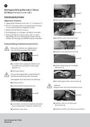
<strong>Montageanleitung</strong> <strong>Mercedes</strong> <strong>ML</strong>/<strong>GL</strong><br />
W/<strong>X164</strong> Airmatic<br />
<strong>Allgemeine</strong> <strong>Hinweise</strong>:<br />
■ Lagerung der Luftfeder nicht unter -15 °C und<br />
über 50°C.<br />
■ Der Ein- und Ausbau darf nur von geschultem<br />
Personal in einer Fachwerkstatt durchgeführt<br />
werden.<br />
■ Zum Umbau ist Werkzeug und Ausrüstung des<br />
Fahrzeugherstellers erforderlich!<br />
■ Die unbefüllte Luftfeder darf nicht mechanisch<br />
belastet werden.<br />
■ Leitungen und Kabel auf Beschädigungen<br />
überprüfen und ggf. ersetzen.<br />
■ Achtung: Erfolgt der Umbau anders, oder in<br />
anderer Reihenfolge, als in der Anleitung<br />
beschrieben, können Schäden an Fahrzeug und<br />
Luftfedermodul entstehen!<br />
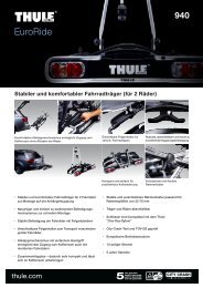
Luftfederausbau hinten<br />
!<br />
Während der Arbeiten am Luftfedermodul<br />
muss die Zündung ausgeschaltet bleiben.<br />
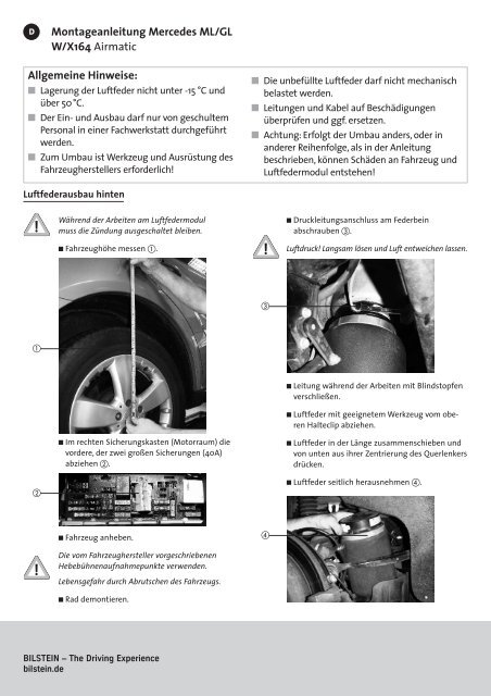
■ Fahrzeughöhe messen .<br />
!<br />
■ Druckleitungsanschluss am Federbein<br />
abschrauben .<br />
Luftdruck! Langsam lösen und Luft entweichen lassen.<br />
<br />
<br />
<br />
■ Im rechten Sicherungskasten (Motorraum) die<br />
vordere, der zwei großen Sicherungen (40A)<br />
abziehen .<br />
■ Leitung während der Arbeiten mit Blindstopfen<br />
verschließen.<br />
■ Luftfeder mit geeignetem Werkzeug vom oberen<br />
Halteclip abziehen.<br />
■ Luftfeder in der Länge zusammenschieben und<br />
von unten aus ihrer Zentrierung des Querlenkers<br />
drücken.<br />
■ Luftfeder seitlich herausnehmen .<br />
!<br />
■ Fahrzeug anheben.<br />
Die vom Fahrzeughersteller vorgeschriebenen<br />
Hebebühnenaufnahmepunkte verwenden.<br />
Lebensgefahr durch Abrutschen des Fahrzeugs.<br />
■ Rad demontieren.<br />
<br />
BILSTEIN – The Driving Experience<br />
bilstein.de
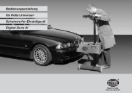
Luftfedereinbau hinten<br />
■ Luftfeder darf beim Einbau nicht verdreht werden.<br />
■ Oberer Halteclip muss erneuert werden.<br />
■ Sicherung einsetzen.<br />
■ Fahrzeug starten, Anhebefunktion der<br />
Bordelektronik betätigen, min. zwei Min. warten<br />
(Fahrzeugtüren geschlossen halten) .<br />
■ Schraubanschluss der neuen Luftfeder abschrauben.<br />
Dabei nicht vorab Kunststoffstopfen entfernen !<br />
<br />
■ Sobald die Luftfeder gefüllt ist, korrekten Sitz<br />
überprüfen .<br />
<br />
■ Alten Druckleitungsanschluss durch Neuteile<br />
ersetzen. Auf korrekte Montage des Konusrings<br />
achten (Konus zeigt in Richtung Druckleitung).<br />
■ Alten Halteclip erneuern .<br />
Dazu Clip vollständig auf Gewindestift am<br />
Karosserieboden schrauben.<br />
<br />
<br />
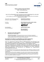
■ Luftfeder mit Ausbuchtung in Zentrierung des<br />
unteren Querlenkers einsetzen.<br />
■ Luftfeder auf dem oberen Halteclip einrasten<br />
lassen.<br />
■ Druckleitung anschrauben (2Nm) .<br />
!<br />
■ Rad montieren.<br />
■ Hebebühne auf ursprüngliches Fahrzeugniveau<br />
ablassen.<br />
Fahrzeug niemals mit druckloser Luftfederung vollständig<br />
von der Hebebühne ablassen.<br />
■ Wenn sich das Fahrzeug selbstständig anhebt,<br />
Hebebühne vollständig ablassen.<br />
■ System auf Dichtheit prüfen<br />
<br />
Hinweis:<br />
BILSTEIN übernimmt keinerlei Haftung für Schäden an Fahrzeug und Teilen<br />
bei unsachgemäßem Austausch. Sämtliche Veränderungen an dem<br />
Luftfedermodul führen zum Erlöschen der Garantie!<br />
E4-WM5-Y369A00
GB<br />
Fitting Information <strong>Mercedes</strong> <strong>ML</strong>/<strong>GL</strong><br />
W/<strong>X164</strong> Airmatic<br />
General information:<br />
■ Do not store suspension modules below -15 °C<br />
or above 50°C.<br />
■ Disassembly and installation are only to be<br />
performed by fully qualified and certified<br />
personnel at a specialized garage.<br />
■ Car manufacturer special tools and equipment<br />
is required!<br />
■ Depressurized suspension modules mustn’t be<br />
exposed to mechanical pressure.<br />
■ Check air pipes and cables – renew if damaged.<br />
■ Caution! Damage to the vehicle and the air<br />
suspension module can occur if work is carried<br />
out in a manner other than that<br />
specified in the instructions or in a different<br />
sequence.<br />
Dismantling the rear suspension module<br />
!<br />
The ignition must remain switched off<br />
during the work on the air suspension module.<br />
■ Measure the standard vehicle height .<br />
!<br />
■ Remove wheel.<br />
■ Unscrew pressure line connection on<br />
suspension module .<br />
Air pressure! Loosen slowly and allow air to escape.<br />
<br />
<br />
■ Seal off line with plugs.<br />
■ Pull off suspension module from upper<br />
holder clip using suitable tools.<br />
■ There are two large fuses (40A) in the right fuse box<br />
(under the hood), remove the front fuse only .<br />
■ Compress suspension module and remove<br />
from the seat of the track control arm.<br />
■ Remove suspension module sideways .<br />
<br />
■ Raise vehicle.<br />
!<br />
Use a chassis hoist and make certain that the raised<br />
vehicle is securely attached to the hoist to prevent<br />
the vehicle from slipping, falling, or moving<br />
during the installation process.<br />
<br />
If you choose to install any BILSTEIN product<br />
without the necessary special tools, expertise or<br />
chassis hoist, you may subject yourself to the risk<br />
of serious bodily injury or death.<br />
Engineered for performance.<br />
bilstein.de
Installing the rear suspension module<br />
■ Do not twist suspension module when installing.<br />
■ Upper holder clip must be renewed.<br />
■ Insert fuse.<br />
■ Start the engine. Operate the raising function<br />
of the on-board electronics, and wait for at least<br />
2 minutes (keep the doors closed during the<br />
period) .<br />
!<br />
■ Unscrew pressure line connection of the new air<br />
suspension module !<br />
Don’t remove plastic plug first.<br />
<br />
■ Check the correct position of suspension<br />
module when it is pressurized .<br />
<br />
■ Replace used parts of the pressure line connection<br />
with new parts. Pay attention to the correct<br />
position of the tapered ring (the cone must go<br />
with the screw connector).<br />
<br />
■ Renew upper holder clip .<br />
Tighten clip to setscrew at the floor pan<br />
completely.<br />
<br />
■ Insert the suspension module into the<br />
index of the track control arm.<br />
■ Put the suspension module on the<br />
upper holder clip.<br />
!<br />
■ Fit wheel.<br />
■ Lower the vehicle up to standard vehicle height<br />
from the lifting platform.<br />
Never under any circumstances allow the vehicle<br />
to be fully lowered from the lifting platform (hoist)<br />
with the air suspension depressurized.<br />
■ Fit air pipe to the top of suspension<br />
module (torque to 2Nm) .<br />
■ Lower completely when the vehicle raises<br />
of its own accord.<br />
■ Check air suspension system for leaks.<br />
<br />
Note:<br />
Manufacturer shall not be liable for any injury, loss or damage resulting<br />
from any improper alteration, disassembly, handling, installation, service,<br />
repair or use of this product, including but not limited to the failure to follow<br />
the foregoing instructions.<br />
Improper alteration, disassembly, handling, installation, service, repair or use<br />
of this product will void the product warranty.<br />
E4-WM5-Y369A00