Installation Instructions - Hoyme Manufacturing Inc.
Installation Instructions - Hoyme Manufacturing Inc.
Installation Instructions - Hoyme Manufacturing Inc.

You also want an ePaper? Increase the reach of your titles
YUMPU automatically turns print PDFs into web optimized ePapers that Google loves.
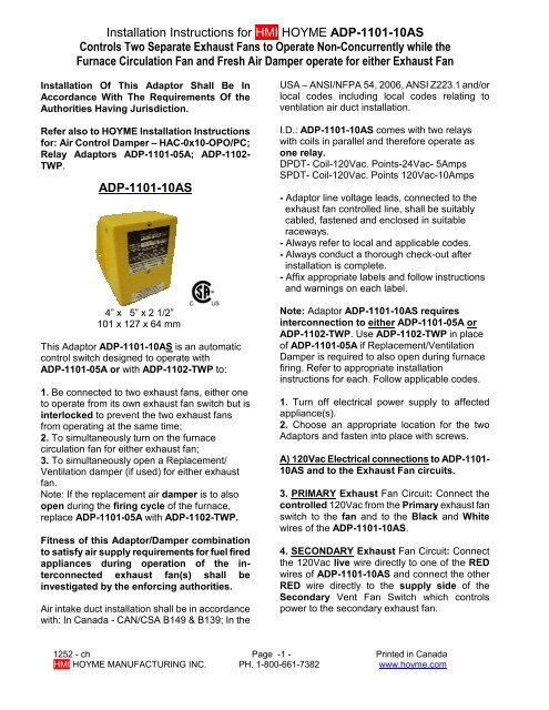
<strong>Installation</strong> <strong>Instructions</strong> for HMI HOYME ADP-1101-10AS<br />
Controls Two Separate Exhaust Fans to Operate Non-Concurrently while the<br />
Furnace Circulation Fan and Fresh Air Damper operate for either Exhaust Fan<br />
<strong>Installation</strong> Of This Adaptor Shall Be In<br />
Accordance With The Requirements Of the<br />
Authorities Having Jurisdiction.<br />
Refer also to HOYME <strong>Installation</strong> <strong>Instructions</strong><br />
for: Air Control Damper – HAC-0x10-OPO/PC;<br />
Relay Adaptors ADP-1101-05A; ADP-1102-<br />
TWP.<br />
ADP-1101-10AS<br />
4” x 5” x 2 1/2”<br />
101 x 127 x 64 mm<br />
This Adaptor ADP-1101-10AS is an automatic<br />
control switch designed to operate with<br />
ADP-1101-05A or with ADP-1102-TWP to:<br />
1. Be connected to two exhaust fans, either one<br />
to operate from its own exhaust fan switch but is<br />
interlocked to prevent the two exhaust fans<br />
from operating at the same time;<br />
2. To simultaneously turn on the furnace<br />
circulation fan for either exhaust fan;<br />
3. To simultaneously open a Replacement/<br />
Ventilation damper (if used) for either exhaust<br />
fan.<br />
Note: If the replacement air damper is to also<br />
open during the firing cycle of the furnace,<br />
replace ADP-1101-05A with ADP-1102-TWP.<br />
Fitness of this Adaptor/Damper combination<br />
to satisfy air supply requirements for fuel fired<br />
appliances during operation of the interconnected<br />
exhaust fan(s) shall be<br />
investigated by the enforcing authorities.<br />
Air intake duct installation shall be in accordance<br />
with: In Canada - CAN/CSA B149 & B139; In the<br />
USA – ANSI/NFPA 54, 2006, ANSI Z223.1 and/or<br />
local codes including local codes relating to<br />
ventilation air duct installation.<br />
I.D.: ADP-1101-10AS comes with two relays<br />
with coils in parallel and therefore operate as<br />
one relay.<br />
DPDT- Coil-120Vac. Points-24Vac- 5Amps<br />
SPDT- Coil-120Vac. Points 120Vac-10Amps<br />
- Adaptor line voltage leads, connected to the<br />
exhaust fan controlled line, shall be suitably<br />
cabled, fastened and enclosed in suitable<br />
raceways.<br />
- Always refer to local and applicable codes.<br />
- Always conduct a thorough check-out after<br />
installation is complete.<br />
- Affix appropriate labels and follow instructions<br />
and warnings on each label.<br />
Note: Adaptor ADP-1101-10AS requires<br />
interconnection to either ADP-1101-05A or<br />
ADP-1102-TWP. Use ADP-1102-TWP in place<br />
of ADP-1101-05A if Replacement/Ventilation<br />
Damper is required to also open during furnace<br />
firing. Refer to appropriate installation<br />
instructions for each. Follow applicable codes.<br />
1. Turn off electrical power supply to affected<br />
appliance(s).<br />
2. Choose an appropriate location for the two<br />
Adaptors and fasten into place with screws.<br />
A) 120Vac Electrical connections to ADP-1101-<br />
10AS and to the Exhaust Fan circuits.<br />
3. PRIMARY Exhaust Fan Circuit: Connect the<br />
controlled 120Vac from the Primary exhaust fan<br />
switch to the fan and to the Black and White<br />
wires of the ADP-1101-10AS.<br />
4. SECONDARY Exhaust Fan Circuit: Connect<br />
the 120Vac live wire directly to one of the RED<br />
wires of ADP-1101-10AS and connect the other<br />
RED wire directly to the supply side of the<br />
Secondary Vent Fan Switch which controls<br />
power to the secondary exhaust fan.<br />
1252 - ch Page -1 - Printed in Canada<br />
HMI HOYME MANUFACTURING INC. PH. 1-800-661-7382 www.hoyme.com
B) 120Vac Electrical Connections for ADP-<br />
1101-05A or ADP-1102-TWP to the Controlled<br />
side of the SECONDARY Vent Fan Switch.<br />
5. Connect the 120Vac controlled side of the<br />
Secondary Vent Fan Switch to the Secondary<br />
Vent Fan and to the Black and White wires of<br />
ADP-1101-05A (-TWP).<br />
C) 24Vac Electrical connections to ADP-1101-<br />
10AS together with ADP-1101-05A (-TWP) which<br />
controls the furnace fan and a Power Open/<br />
Power Close (PO/PC) fresh air damper (if used).<br />
6. Connect thermostat G to 3(Gt) of ADP-1101-<br />
10AS. Connect 4(Gf) of ADP-1101-10AS to 3(Gt)<br />
of ADP-1101-05A (-TWP). Connect 4(Gf) of<br />
ADP-1101 (-TWP) to Furnace G. Connect<br />
terminal 5 of both Adaptors to furnace R.<br />
7. a) If an inlet fresh air damper is used (PO/PC),<br />
connect one damper wire to furnace terminal C.<br />
b) For a PO damper, connect the other damper<br />
wire to terminal 1 of both Adaptors.<br />
- Or -<br />
c) For a PC damper, connect the other wire to 2<br />
of ADP-1101-05A (-TWP). Disconnect terminal 5<br />
of ADP-1101-05A (-TWP) from terminal 5 of ADP-<br />
1101-10AS and reconnect to terminal 2 of ADP-<br />
1101-10AS.<br />
8. Turn on electrical line power to appliance(s). If<br />
damper is a Power Open type, it will remain<br />
closed at this time. If damper is a Power Close<br />
type, it will close at this time.<br />
9. Turn on the Secondary Exhaust Fan Switch.<br />
The Secondary Exhaust Fan, the Furnace<br />
Circulation Fan and the Inlet Damper (if used) will<br />
all operate simultaneously.<br />
10. Turn on the Primary Exhaust Fan Switch. The<br />
Secondary Exhaust Fan will stop while the<br />
Primary Exhaust Fan will run. Note the Furnace<br />
Circulation Fan and Damper continue to operate.<br />
Schematic Wiring Diagram of Adaptor 1101-10AS<br />
Relay Coils: 120Vac; Points 24Vac & 120VAC-10A.<br />
Note: This marking is also on label to be affixed adjacent to appliance wiring diagram.<br />
Additional wire shall be of the same size as originally used when completing electric circuits.<br />
1252 - ch Page -2 - Printed in Canada<br />
HMI HOYME MANUFACTURING INC. PH. 1-800-661-7382 www.hoyme.com