Installation Instructions for HMI HOYME Adaptor 0MV2 Interlocks ...
Installation Instructions for HMI HOYME Adaptor 0MV2 Interlocks ...
Installation Instructions for HMI HOYME Adaptor 0MV2 Interlocks ...

Create successful ePaper yourself
Turn your PDF publications into a flip-book with our unique Google optimized e-Paper software.
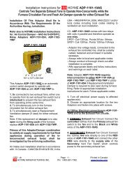
<strong>Installation</strong> <strong>Instructions</strong> <strong>for</strong> <strong>HMI</strong> <strong>HOYME</strong> <strong>Adaptor</strong> <strong>0MV2</strong>-S5A<strong>Interlocks</strong> 24Vac Combustion Air Control Damper To 250mVdc-100 Vdc Safety Control CircuitsINSTALLATION OF THIS ADAPTOR SHALL BEIN ACCORDANCE WITH THE REQUIREMENTSOF THE AUTHORITIES HAVING JURISDICTION.Refer also to <strong>HMI</strong> <strong>HOYME</strong> <strong>Installation</strong> <strong>Instructions</strong>:‘Combustion Air Control Damper, Series HOM.’ADP-OMV2-S5A4” x 5” x 2 1/2”101 x 127 x 64 mmThis <strong>Adaptor</strong> comes with two relays and aprinted circuit which senses a 250 mVdc/100Vdc safety control circuit, opens a 24Vacdamper and then signals back to the safetycircuit <strong>for</strong> firing. For line voltage AC safetycontrol circuits, use <strong>Adaptor</strong> ADP-1102-S5A.I.D.: ADP-<strong>0MV2</strong>-S5A Includes:-Test/Run Switch,-Printed Circuit Board with Relays-Main Coil 24Vac. Points 24Vac/5Amps.- For one appliance, use one <strong>Adaptor</strong> andone Damper, Series HOM, Type – SF1.- For two appliances, use two <strong>Adaptor</strong>s andone Damper, Series HOM, Type SF1.- <strong>Adaptor</strong> is to be mounted as close aspossible to 250 mVdc/100Vdc gas valve.- Additional wire shall not be spliced to theRED, BLACK or WHITE leads.- Use an approved 24Vac trans<strong>for</strong>mer ofadequate capacity (10 VA min.)- Supply <strong>for</strong> the primary of the trans<strong>for</strong>mershall be taken from the line voltage supply<strong>for</strong> the appliance. Follow applicable codes.-Always conduct a thorough check-out afterinstallation is complete.-Affix attached wiring diagram label adjacentto appliance wiring diagram label.Note: Numbers 1 to 6 includes interconnectingthe <strong>Adaptor</strong> to the Damper.1.Turn temperature control to lowest setting.2. Turn off electric power. Add a 24Vactrans<strong>for</strong>mer to power the damper closed.(See # 4) Follow applicable Codes.3. Connect damper wires BLACK (1), RED(2), BROWN (3) to <strong>Adaptor</strong> terminals 1, 2and 3 respectively. Note: Connect damperwire BLUE (5) to <strong>Adaptor</strong> terminal 4.4. Connect 24Vac trans<strong>for</strong>mer wires to<strong>Adaptor</strong> terminals 3 and 5.5. Turn on electric power to trans<strong>for</strong>mer.Damper will close.Note: ‘TEST/RUN’ manual switches on thedamper and adaptor are to be in the ‘RUN’position.6. Test <strong>for</strong> common ground by touchingWHITE <strong>Adaptor</strong> lead to base of gas valve. Ifsparking occurs, interchange trans<strong>for</strong>merwires on <strong>Adaptor</strong> terminals 3 and 5.Note: Numbers 7 to 11 includes interconnectingthe <strong>Adaptor</strong> to the power pile ofa mVdc circuit.Note: Pilot light to remain burning.<strong>Adaptor</strong> leads BLACK and WHITE must beproperly matched to the dc polarity of thepower pile with the Pilot light burning.7. Test by touching <strong>Adaptor</strong> WHITE lead tothermopile wire on terminal (PP) on Coil sideof the gas valve while touching <strong>Adaptor</strong>BLACK lead to remaining thermopile wire.Damper should now open. If no response,exchange <strong>Adaptor</strong> leads and retest.1212-ch 1 Printed in Canada
8. Connect this WHITE ‘lead/thermopile’wires to (PP) terminal on coil side of the gasvalve. (This might require inter-changingthermopile wires <strong>for</strong> proper polarity of DCcurrent and relight pilot if necessary.)9. Disconnect temperature control wireleading to the TH terminal on gas valve coiland replace with the <strong>Adaptor</strong> RED wire.10. Rejoin the temperature control wire tothe <strong>Adaptor</strong> BLACK lead with a screw-onwire connector.11. Turn temperature control to call <strong>for</strong> heat.Damper will open and heating appliance willoperate normally.Note: Numbers 12 to 17 includes interconnectingthe <strong>Adaptor</strong> to dc circuits otherthan the mVdc.17. Turn on the power. Turn temperaturecontrol to call <strong>for</strong> heat. Damper will open andheating appliance will operate normally.ON DC CIRCUITS OTHER THAN mVdccircuits, the BLACK and WHITE leads shallalso be matched to the dc polarity of thesafety circuit.CAUTION: <strong>Adaptor</strong> leads BLACK, REDand WHITE are to be connected to the250mVdc-100Vdc safety circuit only.SCHEMATIC WIRING DIAGRAM FORCOMBUSTION AIR CONTROL DAMPERINTERLOCKED TO MILLIVOLT SAFETYCONTROL CIRCUIT USING ADAPTOR ‘<strong>0MV2</strong>’.SAFETY NOTE:Higher voltage requires EXTRA CAUTION.12. <strong>Adaptor</strong> leads BLACK and WHITE mustbe properly matched to the dc polarity of thesafety circuit.13. Test by touching <strong>Adaptor</strong> WHITE andBLACK wires to the dc source leading to thegas valve. If damper does not open, reversethe Black and WHITE leads and the damperwill open. Note this polarity combination.SAFETY NOTE: With voltages other thanmVdc, turn the supply power off.14. Connect the WHITE lead wire to the gasvalve as per polarity combination found in 7.15. On the other side of the gas valvedisconnect the dc wire and replace it withthe <strong>Adaptor</strong> RED wire.16. To the wire removed in #9 connect the<strong>Adaptor</strong> BLACK wire with the wire nutsupplied.Note: This marking is also on label to beaffixed adjacent to appliance wiring diagram.Additional wire shall be of the same size andtype as originally used when completing theabove circuit.1212-ch 2 Printed in CanadaFor more in<strong>for</strong>mation, please contact <strong>HMI</strong> <strong>HOYME</strong> Manufacturing Inc. @ 1-800-661-7382www.hoyme.com