FDB2 FIRE AND GAS DAMPER - Halton
FDB2 FIRE AND GAS DAMPER - Halton
FDB2 FIRE AND GAS DAMPER - Halton

You also want an ePaper? Increase the reach of your titles
YUMPU automatically turns print PDFs into web optimized ePapers that Google loves.
<strong>FDB2</strong> Installation, operation and<br />
maintenance instructions<br />
Version: 10<br />
Date: 19.12.2012<br />
<strong>FDB2</strong><br />
<strong>FIRE</strong> <strong>AND</strong> <strong>GAS</strong> <strong>DAMPER</strong><br />
INSTALLATION, OPERATION <strong>AND</strong><br />
MAINTENANCE INSTRUCTIONS<br />
Main sales office & factory<br />
Tel. +358 (0)2079 2200<br />
Fax. +358 (0)2079 22060<br />
http://www.haltonmarine.com<br />
Page 1 of 21
<strong>FDB2</strong> Installation, operation and<br />
maintenance instructions<br />
Version: 10<br />
Date: 19.12.2012<br />
Table Of Contents<br />
Chapter<br />
Page<br />
1. INSTALLATION INSTRUCTIONS ....................................................................................................................... 3<br />
1.1. General ............................................................................................................................................................ 3<br />
1.2. Installation of dampers .................................................................................................................................... 4<br />
1.3. Lifting instructions ............................................................................................................................................ 5<br />
1.4. Assembly in modules ....................................................................................................................................... 6<br />
2. OPERATION INSTRUCTIONS FOR ELECTRICAL <strong>DAMPER</strong>S ........................................................................ 9<br />
2.1. General ............................................................................................................................................................ 9<br />
2.2. Electrical control system .................................................................................................................................. 9<br />
2.3. Manual override ............................................................................................................................................... 9<br />
2.4. Wiring diagrams ............................................................................................................................................. 10<br />
3. OPERATION INSTRUCTIONS FOR PNEUMATIC <strong>DAMPER</strong>S ....................................................................... 13<br />
3.1. Normal operation ........................................................................................................................................... 13<br />
3.2. Manual override ............................................................................................................................................. 13<br />
4. INSTRUCTIONS FOR SPRING OPERATED <strong>DAMPER</strong> ................................................................................... 15<br />
5. MAINTENANCE................................................................................................................................................. 16<br />
5.1. Preventative ................................................................................................................................................... 16<br />
5.2. Service- and maintenance instructions.......................................................................................................... 16<br />
5.3. Corrective ...................................................................................................................................................... 17<br />
5.4. Instructions for replacing the fusible link........................................................................................................ 18<br />
6. ACCESSORIES ................................................................................................................................................. 19<br />
6.1. Circular counter flanges ................................................................................................................................. 19<br />
6.2. Rectangular counter flanges .......................................................................................................................... 19<br />
6.3. FD-CON-2 Fire Damper Switch ..................................................................................................................... 20<br />
6.4. FD-CON-R Advanced Fire Damper Switch ................................................................................................... 20<br />
6.5. External limit switches (2pcs Bernstein) ........................................................................................................ 20<br />
7. SPARE PART LIST ........................................................................................................................................... 21<br />
Main sales office & factory<br />
Tel. +358 (0)2079 2200<br />
Fax. +358 (0)2079 22060<br />
http://www.haltonmarine.com<br />
Page 2 of 21
<strong>FDB2</strong> Installation, operation and<br />
maintenance instructions<br />
Version: 10<br />
Date: 19.12.2012<br />
1. INSTALLATION INSTRUCTIONS<br />
1.1. GENERAL<br />
Before any activity for installing the fire damper can be executed, ensure that:<br />
dimensions of fire damper and relevant penetration correspond.<br />
correct location has been selected.<br />
technical- and supply data of relevant fire damper correspond with requirements.<br />
Take into account the necessary service area, space for insulation dimensions and the motor side of the<br />
damper.<br />
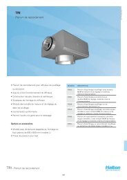
Connections to circular ducts are enabled with separate installation frames that can be welded (or bolted with<br />
installation flanges + counter flanges) to ducts (see below). Installation frames can be ordered either for only<br />
one or for both sides of the damper.<br />
Main sales office & factory<br />
Tel. +358 (0)2079 2200<br />
Fax. +358 (0)2079 22060<br />
http://www.haltonmarine.com<br />
Page 3 of 21
<strong>FDB2</strong> Installation, operation and<br />
maintenance instructions<br />
Version: 10<br />
Date: 19.12.2012<br />
1.2. INSTALLATION OF <strong>DAMPER</strong>S<br />
IN ACCORDANCE WITH SOLAS II-2/9.7.3.1.2 THE <strong>DAMPER</strong> SHOULD BE INSTALLED IN ORDER TO<br />
DELIVER CLEAR VIEW ON THE RED ARROW THAT INDICATES THE <strong>DAMPER</strong> POSITION<br />
When lifting or handling the fire damper, care must be taken to protect the mechanism from damage.<br />
DO NOT LIFT THE <strong>FIRE</strong> <strong>DAMPER</strong> BY THE ACTIVATING MECHANISM.<br />
After installation it is also advisable to protect the mechanism from dirt and mechanical damage, until<br />
the commissioning and/or final acceptance activities start (for instance: a wooden covering box).<br />
The fire damper can be installed in a horizontal, vertical or inclined position. However, it is<br />
recommended to provide the blade spindle to remain in the horizontal plane.<br />
In case of passing through decks or bulkheads, the fire damper shall be flanged on a separate<br />
penetration sleeve. These sleeves are mostly manufactured out of the same material and fire rating<br />
as the deck or bulkhead in which they are located, and provided with corresponding counter flanges.<br />
A suitable gasket if needed must be included between the flange faces to seal the joint.<br />
The fire damper must be installed square and true. Any distortion of the casing may cause jamming<br />
during operation.<br />
If the fire damper has to be insulated after installation (pending on the fire rating) ensure that the<br />
insulation does not impede the operation of the damper.<br />
The damper is approved for use in ducts penetrating bulkhead or deck Class A-0/A-15/A-30/A-60<br />
when damper and ventilation penetration are insulated similarly. The arrangement and necessary<br />
insulation of fire dampers frame and ducting in the vicinity of the partition is subject to approval in<br />
each case.<br />
If the fire damper is installed above a ceiling or under a false floor, an inspection/access hatch shall<br />
be provided for the accessibility for tests, service and/or maintenance.<br />
Different connections and connection methods are available through use of installation frames and flanges<br />
Main sales office & factory<br />
Tel. +358 (0)2079 2200<br />
Fax. +358 (0)2079 22060<br />
http://www.haltonmarine.com<br />
Page 4 of 21
<strong>FDB2</strong> Installation, operation and<br />
maintenance instructions<br />
Version: 10<br />
Date: 19.12.2012<br />
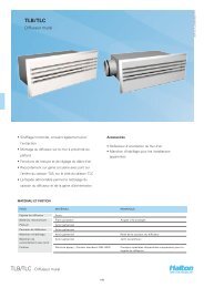
1.3. LIFTING INSTRUCTIONS<br />
When lifting the damper, care must be taken to protect the mechanism and equipment from damage. Lift the<br />
damper only from the damper body. If the damper is lifted from above the damper lifting holes should be<br />
used. The damper can also be lifted either from below or by the installation holes if it is possible and<br />
permitted by other working regulations.<br />
DO NOT LIFT THE <strong>DAMPER</strong> BY THE ACTUATING MECHANISM OR FUSE MECHANISM.<br />
Main sales office & factory<br />
Tel. +358 (0)2079 2200<br />
Fax. +358 (0)2079 22060<br />
http://www.haltonmarine.com<br />
Page 5 of 21
<strong>FDB2</strong> Installation, operation and<br />
maintenance instructions<br />
Version: 10<br />
Date: 19.12.2012<br />
1.4. ASSEMBLY IN MODULES<br />
Modular dampers are usually shipped in separate modules with all necessary connection parts attached.<br />
When assembling modules, please check that you have all the necessary parts:<br />
- With dampers there are flat steel bars attached to the shipment<br />
- Flat steel bars are equipped with appropriate size bolts for all threaded holes.<br />
- 4-module dampers are also shipped with two cross-shaped connection pieces.<br />
- A suitable amount of sealant material is supplied with each modular damper shipment.<br />
If you cannot find flat steel bars or bolts for the threaded holes, please check the damper shipment for<br />
attachments or other possibilities of loose items. If you are certain the flat steel bars, bolts or sealant<br />
tubes are not with the damper shipment, please contact <strong>Halton</strong> Marine.<br />
1.4.1. Sealant instructions<br />
Instructions for applying Pyrocryl (or similar) sealant:<br />
1. Check that the the each connection piece matches with the<br />
damper modules before applying the sealant.<br />
2. Apply a constant stream of sealant to each flat steel bar and the<br />
cross pieces.<br />
3. Install the flat steel bars and cross pieces as instructed.<br />
Main sales office & factory<br />
Tel. +358 (0)2079 2200<br />
Fax. +358 (0)2079 22060<br />
http://www.haltonmarine.com<br />
Page 6 of 21
<strong>FDB2</strong> Installation, operation and<br />
maintenance instructions<br />
Version: 10<br />
Date: 19.12.2012<br />
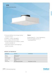
1.4.2. Damper connection instructions<br />
2-module damper<br />
Note that 2 modules can also be attached vertically.<br />
Main sales office & factory<br />
Tel. +358 (0)2079 2200<br />
Fax. +358 (0)2079 22060<br />
http://www.haltonmarine.com<br />
Page 7 of 21
<strong>FDB2</strong> Installation, operation and<br />
maintenance instructions<br />
Version: 10<br />
Date: 19.12.2012<br />
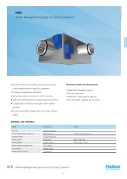
4-module damper<br />
NOTE: 4-module dampers are shipped with cross-shaped connection pieces (figure 6). Install a connection<br />
piece on both side of the damper for maximum air tightness (figure 7).<br />
IMPORTANT NOTICE!<br />
If a module damper is delivered already assembled as per customer request, it is the duty of the<br />
customer to tighten all module construction bolts in the installation phase!<br />
Main sales office & factory<br />
Tel. +358 (0)2079 2200<br />
Fax. +358 (0)2079 22060<br />
http://www.haltonmarine.com<br />
Page 8 of 21
<strong>FDB2</strong> Installation, operation and<br />
maintenance instructions<br />
Version: 10<br />
Date: 19.12.2012<br />
2. OPERATION INSTRUCTIONS FOR ELECTRICAL <strong>DAMPER</strong>S<br />
2.1. GENERAL<br />
Electrical dampers can be fitted with many different types of electrical actuators that operate the damper<br />
blades. Electrical actuators usually include internal open/closed limit switches that can be used to detect the<br />
position of the damper from remote systems.<br />
The voltage and current required for each damper depends on the type of actuator.<br />
2.2. ELECTRICAL CONTROL SYSTEM<br />
Supply voltage depending on the actuator type is supplied to the junction box. This is connected via a micro<br />
switch/ fusible link assembly to the drive Actuator. This supply voltage provides the motive force to open the<br />
damper blade in which position it will remain as long as the supply voltage is maintained.<br />
Isolation of the Actuator from the supply voltage allow the spring-return forces in the Actuator to rotate it back<br />
through 90 degrees to the damper “closed” position. This is the basis of the “fail safe closed” mode of control.<br />
The movement of the damper blades is accomplished with a rotary, single-acting, spring-return Actuator,<br />
which is directly attached to one of the blade drive shafts. The other blades are connected to the driven shaft<br />
by means of a linkage mechanism. The damper open and closed conditions are selected by energizing or deenergizing<br />
the control voltage supply.<br />
The damper can be controlled from remote systems simply by turning the supply power on and off. Local<br />
control and monitoring can be achieved with FD-CON-2 accessory control boxes. Multitude of different<br />
additional limit switches and other components can be installed to the damper according to order<br />
specification.<br />
2.2.1. Normal operation<br />
A) To select damper ‘OPEN’ energize control voltage supply. Supply voltage will then pass via the micro<br />
switch /fusible link assembly into the damper Actuator hence opening the damper.<br />
B) To select damper ‘CLOSED’ de-energize the control voltage supply. The spring return Actuator closes<br />
the damper.<br />
2.2.2. Automatic damper closing<br />
The damper will automatically ‘CLOSE’ if the temperature of the air within the damper duct exceeds 50<br />
(option 74, 100) degrees centigrade thus breaking the fusible link which allows the micro switch to go into<br />
the “closed” position thus de-energies the spring return Actuator.<br />
2.3. MANUAL OVERRIDE<br />
Manual override functions for electrical dampers are always a special solution and depends heavily on the<br />
type of actuator used. If the manual override function is required in the order specification then a separate<br />
detailed manual will be supplied for this operation.<br />
Main sales office & factory<br />
Tel. +358 (0)2079 2200<br />
Fax. +358 (0)2079 22060<br />
http://www.haltonmarine.com<br />
Page 9 of 21
<strong>FDB2</strong> Installation, operation and<br />
maintenance instructions<br />
Version: 10<br />
Date: 19.12.2012<br />
2.4. WIRING DIAGRAMS<br />
Models BF24, BLF24, BF120/230, BLF120<br />
Models BF24-T, BF230-T<br />
Main sales office & factory<br />
Tel. +358 (0)2079 2200<br />
Fax. +358 (0)2079 22060<br />
http://www.haltonmarine.com<br />
Page 10 of 21
<strong>FDB2</strong> Installation, operation and<br />
maintenance instructions<br />
Version: 10<br />
Date: 19.12.2012<br />
Models Siemens GGA.126.1E/HA, GGA.226.1E/HA, GGA326.1E/HA, GNA.126.1E/HA, GNA.326.1E/HA<br />
Models Siemens GGA.126.1E/HA1, GGA326.1E/HA1<br />
Main sales office & factory<br />
Tel. +358 (0)2079 2200<br />
Fax. +358 (0)2079 22060<br />
http://www.haltonmarine.com<br />
Page 11 of 21
<strong>FDB2</strong> Installation, operation and<br />
maintenance instructions<br />
Version: 10<br />
Date: 19.12.2012<br />
Models ExMax & RedMax (10 second closing time)<br />
Models ExMax & RedMax (3 second closing time)<br />
Main sales office & factory<br />
Tel. +358 (0)2079 2200<br />
Fax. +358 (0)2079 22060<br />
http://www.haltonmarine.com<br />
Page 12 of 21
<strong>FDB2</strong> Installation, operation and<br />
maintenance instructions<br />
Version: 10<br />
Date: 19.12.2012<br />
3. OPERATION INSTRUCTIONS FOR PNEUMATIC <strong>DAMPER</strong>S<br />
3.1. NORMAL OPERATION<br />
Under normal operating conditions when instrument air is applied the pneumatic actuator holds the damper<br />
blades in the open position.<br />
Pneumatic damper requires a supply of clean and dry instrument air of 4-8 bar pressure. When air supply is<br />
cut, or pressure drops too low, the damper will automatically close.<br />
In a fire condition when the air temperature in the duct rises too high the spring loaded fusible link breaks and<br />
cuts the air supply via the fusible link valve. The limit temperature can be chosen with different temperature<br />
fusible links, the default temperature limit is 74°C.<br />
A quick exhaust valve is also installed in the pneumatic circuit of each fire damper. The purpose of this relief<br />
valve is to ease the vent-action.<br />
When the air pressure difference between the air supply line and the outgoing line to the pneumatic Actuator<br />
exceeds 1 bar the valve will automatically vent the outgoing line. Herewith the time for closing the fire damper<br />
blade will be shortened considerably.<br />
Fire dampers can be provided with multitude of different instruments and limit switches according to order<br />
specification.<br />
3.2. MANUAL OVERRIDE<br />
PNR (pneumatic rotating) type dampers can be fitted with manual override handle. Below is the graphical<br />
instruction for using the handle.<br />
Main sales office & factory<br />
Tel. +358 (0)2079 2200<br />
Fax. +358 (0)2079 22060<br />
http://www.haltonmarine.com<br />
Page 13 of 21
<strong>FDB2</strong> Installation, operation and<br />
maintenance instructions<br />
Version: 10<br />
Date: 19.12.2012<br />
PNL (pneumatic linear) type dampers dampers can be fitted with manual override handle.<br />
Main sales office & factory<br />
Tel. +358 (0)2079 2200<br />
Fax. +358 (0)2079 22060<br />
http://www.haltonmarine.com<br />
Page 14 of 21
<strong>FDB2</strong> Installation, operation and<br />
maintenance instructions<br />
Version: 10<br />
Date: 19.12.2012<br />
4. INSTRUCTIONS FOR SPRING OPERATED <strong>DAMPER</strong><br />
A) Under normal operating conditions the fire damper blade is held in the “open” position by the arm (pos 1)<br />
and connecting rod of fusible link (pos 2).<br />
The internal fusible link includes a fusible link (pos 2), which in turn holds a spring return connecting rod. This<br />
connecting rod holds the spring (pos 4) and fire damper in open position.<br />
B) The fusible link is temperature sensitive and when the air passing through and/or the air surround the fire<br />
damper reaches a temperature of approximately 74 º°C, the link will shatter.<br />
When the link smelts (pos 2) the connecting-rod is released and the spring (pos 4) will close the fire damper.<br />
°C) If you want close the damper manually pull the knob (pos 3) release and the external spring (pos 4) will<br />
close the fire damper.<br />
To reset the damper to close position pull the knob (pos 3) and rotate the arm counter-clockwise (pos 1) over<br />
the clamp up to the position of the connecting rod. Then set the shaft of the knob (pos 3) into the end section of<br />
connecting rod.<br />
WARNING:<br />
DURING RELEASE <strong>AND</strong> RESET OPERATION BE SURE THAT THERE IS NO RISK TO HURT<br />
YOURSELF!!!<br />
Main sales office & factory<br />
Tel. +358 (0)2079 2200<br />
Fax. +358 (0)2079 22060<br />
http://www.haltonmarine.com<br />
Page 15 of 21
<strong>FDB2</strong> Installation, operation and<br />
maintenance instructions<br />
Version: 10<br />
Date: 19.12.2012<br />
5. MAINTENANCE<br />
5.1. PREVENTATIVE<br />
Regularly the damper shall have a functional test, to ensure that the blades are opening and closing<br />
satisfactorily. This test should also confirm that local (and possibly remote) indicators show the correct status<br />
of the damper.<br />
The recommended schedule of functional testing: Once a month.<br />
A complete visual and functional test shall be scheduled annually.<br />
This inspection should include a check on the blades inside the duct for any dirt or foreign matter.<br />
Remove the dirt (if found) and clean the inside of the damper housing.<br />
All electrical and/or pneumatic components shall be checked for any sings of failure.<br />
Components found, which are preventing the damper from operating satisfactorily, should be replaced.<br />
The recommended schedule for fusible link package change: Every five years<br />
It is recommended that the fusible link rod that goes from the fusible link to the limit switch/pneumatic valve<br />
(see drawing below) is sprayed with “PRF Teflube or similar” annually.<br />
5.2. SERVICE- <strong>AND</strong> MAINTENANCE INSTRUCTIONS<br />
The electrical and compressed air power sources, used in some of the components of the fire damper, are at<br />
a level high enough to be dangerous.<br />
Before carrying out any service, maintenance and/or repair work, the appropriate power sources must be<br />
isolated and checks shall be made to ensure that safe conditions exist.<br />
Whenever work is to be carried out on motive plants or equipment, the fuses or at least the main switch,<br />
covering this item, should be removed/turned off as an added safety.<br />
Main sales office & factory<br />
Tel. +358 (0)2079 2200<br />
Fax. +358 (0)2079 22060<br />
http://www.haltonmarine.com<br />
Page 16 of 21
<strong>FDB2</strong> Installation, operation and<br />
maintenance instructions<br />
Version: 10<br />
Date: 19.12.2012<br />
5.3. CORRECTIVE<br />
On standard <strong>Halton</strong> fire damper all electrical and/or pneumatic components are mounted on one base panel<br />
to ease the corrective activities.<br />
Isolate electrical- and/or instrument air supply from the damper, before any corrective action can be<br />
executed.<br />
How the repairs and/or replacement of components shall be executed are described and indicated hereafter.<br />
ELECTRICAL MODELS<br />
Failure Possible cause Remedy<br />
Damper does not open Supply power not available Check supply power lines<br />
Fire damper controls are inhibited<br />
(alarm is on)<br />
Check the inhibit controls and reset the<br />
controls if conditions are safe<br />
Operating mechanism is jammed Check the activating mechanism for any<br />
foreign matter and clean if necessary<br />
Fusible link is broken<br />
Check both fusible links and replace if<br />
broken (one inside damper, other inside<br />
junction box)<br />
Also check the operation of fusible link<br />
limit switch<br />
Fire damper blade is blocked Clean the insides of the damper casing<br />
Damper does not close Fusible link limit switch blocked Check fusible link limit switch<br />
Spring operation fails<br />
Check function of the Actuator<br />
Operating mechanism is jammed Check the activating mechanism for any<br />
foreign matter and clean if necessary<br />
Fire damper blade is blocked Clean the insides of the damper casing<br />
PNEUMATIC MODELS<br />
Failure Possible cause Remedy<br />
Damper does not open Instrument air not available Check instrument air lines<br />
Check air supply valves<br />
Check three-way valve<br />
Instrument air pressure too low Check instrument air lines<br />
Check instrument air filters<br />
Check instrument air reducers<br />
Fire damper controls are inhibited<br />
(alarm is on)<br />
Check the inhibit controls and reset the<br />
controls if conditions are safe<br />
Operating mechanism is jammed Check the activating mechanism for any<br />
foreign matter and clean if necessary<br />
Fusible link is broken<br />
Check fusible link and replace if broken<br />
Fire damper blade is blocked Clean the insides of the damper casing<br />
Damper does not close Instrument air vent blocked Check automatic vent and clean the vent<br />
opening<br />
Spring operation fails<br />
Check function of the spring (inside the<br />
Actuator) and replace spring/Actuator if<br />
necessary<br />
Operating mechanism is jammed Check the activating mechanism for any<br />
foreign matter and clean if necessary<br />
Fire damper blade is blocked<br />
Quick exhaust valve is not<br />
functioning<br />
Clean the insides of the damper casing<br />
Check and clean the quick exhaust valve<br />
or replace if necessary<br />
Main sales office & factory<br />
Tel. +358 (0)2079 2200<br />
Fax. +358 (0)2079 22060<br />
http://www.haltonmarine.com<br />
Page 17 of 21
<strong>FDB2</strong> Installation, operation and<br />
maintenance instructions<br />
Version: 10<br />
Date: 19.12.2012<br />
5.4. INSTRUCTIONS FOR REPLACING THE FUSIBLE LINK<br />
When a fusible link breaks the damper closes and will remain closed as long as the fusible link remains<br />
unfixed. To fix the fusible link you must either A) replace the broken link, or B) replace the whole fusible link<br />
package with a new fusible link package. In case B remember to rewire the junction box (or pneumatic lines in<br />
case of pneumatic damper) exactly like it was before.<br />
1. Open fixing bolts (figure 2) and withdraw the complete thermo intermediate link.<br />
2. Press the spring (figure 3) and insert new fusible link to the spring. Note: Ensure that the replaced<br />
fusible link has the same temperature rating as the old one.<br />
3. Reinstall the thermo intermediate link and tighten the fixing bolts (figure 5).<br />
1 2<br />
3 4<br />
5 6<br />
Main sales office & factory<br />
Tel. +358 (0)2079 2200<br />
Fax. +358 (0)2079 22060<br />
http://www.haltonmarine.com<br />
Page 18 of 21
<strong>FDB2</strong> Installation, operation and<br />
maintenance instructions<br />
Version: 10<br />
Date: 19.12.2012<br />
6. ACCESSORIES<br />
6.1. CIRCULAR COUNTER FLANGES<br />
6.2. RECTANGULAR COUNTER FLANGES<br />
Main sales office & factory<br />
Tel. +358 (0)2079 2200<br />
Fax. +358 (0)2079 22060<br />
http://www.haltonmarine.com<br />
Page 19 of 21
<strong>FDB2</strong> Installation, operation and<br />
maintenance instructions<br />
Version: 10<br />
Date: 19.12.2012<br />
6.3. FD-CON-2 <strong>FIRE</strong> <strong>DAMPER</strong> SWITCH<br />
The FD-CON-2 fire damper switch is a control unit for <strong>Halton</strong> fire dampers. The control unit is installed near<br />
the damper in a place where personnel has easy and logical access to it. Two or more FD-CON-2 units can<br />
be connected in series. This allows the damper to be locally controlled from both sides of the bulkhead or<br />
deck as per SOLAS regulation.<br />
The FD-CON-2 is mainly intended for electrically operated dampers, but it can also be used for pneumatic<br />
dampers. In this case the FD-CON-2 unit controls the solenoid valve that controls the supply air to the<br />
damper actuator.<br />
6.4. FD-CON-R ADVANCED <strong>FIRE</strong> <strong>DAMPER</strong> SWITCH<br />
The FD-CON-R advanced fire damper switch is a control unit for <strong>Halton</strong> fire dampers with remote control and<br />
monitoring functions. The control unit is installed near the damper in a place where personnel has easy and<br />
logical access to it. Two FD-CON-R units can be connected in series. This allows the damper to be locally<br />
controlled from both sides of the bulkhead or deck as per SOLAS regulation. In addition the FD-CON-R unit<br />
can be remotely controlled and monitored from a central control station.<br />
The FD-CON-R is mainly intended for electrically operated dampers, but it can also be used for pneumatic<br />
dampers. In this case the FD-CON-R unit controls the solenoid valve that controls the supply air to the<br />
damper actuator. This manual only describes the basic setup for electrical actuators.<br />
6.5. EXTERNAL LIMIT SWITCHES (2PCS BERNSTEIN)<br />
To enable accurate remote indication of damper blade position two<br />
external micro switches and a red position indicator arrow can be<br />
mounted in to the Actuator.<br />
Mechanical features of the limit switches:<br />
Enclosure & cover:<br />
Actuator:<br />
Contact type:<br />
Mechanical life:<br />
Mounting:<br />
Connection type:<br />
Conductor cross-section:<br />
Cable entry size:<br />
Weight:<br />
Thermoplast + glassfiber<br />
Push bolt (Thermoplast)<br />
1 NC-contact, 1 NO-contact<br />
10x10 6 switch operations<br />
2 x M4<br />
4 screw connections (M3.5)<br />
Single core 0.5-1.5mm 2 /litz wire with connector sleeve 0.5-1.5mm<br />
1 x M20x1.5<br />
approx. 0,06kg<br />
Electrical features of the limit switches:<br />
Rated insulation voltage:<br />
U i = 250V AC<br />
Conventional thermal current: I the = 10A<br />
Max. inrush current:<br />
according to IEC 60947-5, AC 15, A300<br />
Utilization categorie:<br />
AC 15, A300, U e /I e 240V/3A<br />
Standards: according to EN 60947-1, EN 60947-5-1<br />
Protection class:<br />
IP65 according to EN60529, DIN VDE 0470 T1<br />
CSA:<br />
10A 300V AC, A300 (some polarity)<br />
Short-circuit protection:<br />
Fuse 2A gL/gG, IEC/EN 60947-5-1, appendix K<br />
Main sales office & factory<br />
Tel. +358 (0)2079 2200<br />
Fax. +358 (0)2079 22060<br />
http://www.haltonmarine.com<br />
Page 20 of 21
<strong>FDB2</strong> Installation, operation and<br />
maintenance instructions<br />
Version: 10<br />
Date: 19.12.2012<br />
7. SPARE PART LIST<br />
Material number Short description Fire damper model<br />
100000242SP Actuator BF120-2 HL EL<br />
100000223SP Actuator BF230-2.1 HL EL<br />
100000224SP Actuator BF230-T-2 HL EL<br />
100000222SP Actuator BF24-2.1HL EL<br />
100000225SP Actuator BF24-T-2 HL EL<br />
100000325SP Actuator RedMax 15-F EL<br />
100000326SP Actuator RedMax 15-SF EL<br />
100000327SP Actuator ExMax 15-F EL<br />
100000328SP Actuator ExMax 15-SF EL<br />
100000108SP Actuator InMax 15-SF EL<br />
100000101SP Linear pneumatic spring return actuator 245 N PNL<br />
100000100SP Linear pneumatic spring return actuator 300 N PNL<br />
100000258SP Rotating pneumatic actuator AT100 PNR<br />
100000259SP Rotating pneumatic actuator AT100 (AISI316) PNR<br />
100000394SP Fusible link package EL HFE 74 °C EL<br />
100000395SP Fusible link package EL galvanized 74 °C EL<br />
100000398SP Fusible link package SP HFE 74 °C SP<br />
100000399SP Fusible link package SP galvanized 74 °C SP<br />
100000397SP Fusible link package PNL 343/2 (Mecman) HFE 74 °C PNL, PNR<br />
100000396SP Fusible link package PNL 343/2 (Mecman) galvanized 74 °C PNL, PNR<br />
100000293SP Fusible link 144 °C ALL<br />
100000193SP Fusible link 144 °C with fuse springs ALL<br />
100000091SP Fusible link 100 °C ALL<br />
100000094SP Fusible link 100 °C with fuse springs ALL<br />
100000090SP Fusible link 74 °C ALL<br />
100000093SP Fusible link 74 °C with fuse springs ALL<br />
100000292SP Fusible link 72 °C ALL<br />
100000089SP Fusible link 50 °C ALL<br />
100000092SP Fusible link 50 °C with fuse springs ALL<br />
100000096SP Pressure regulator PNL, PNR<br />
100000097SP Pressure gauge PNL, PNR<br />
100000098SP Quick exhaust valve PNL, PNR<br />
100000086SP Explosion Proof solenoid valve 2/3 230 VDC PNL, PNR<br />
100000085SP Explosion Proof solenoid valve 2/3 24 VDC PNL, PNR<br />
100000084SP Solenoid valve 230 VDC PNL, PNR<br />
100000083SP Solenoid valve 24 VDC PNL, PNR<br />
100000060SP Junction box ABS EL, PNL, PNR<br />
100000080SP Limit switch 188-SU1ZW (Bernstein) EL, PNL, PNR<br />
100000081SP Explosion Proof Limit switch 07-2511-1330/63 (Bartec) EL, PNL, PNR<br />
100000438SP FD-CON-2 Slave ALL<br />
100000439SP FD-CON-2 Main ALL<br />
100000440SP FD-CON-R Slave ALL<br />
100000441SP FD-CON-R Main ALL<br />
Main sales office & factory<br />
Tel. +358 (0)2079 2200<br />
Fax. +358 (0)2079 22060<br />
http://www.haltonmarine.com<br />
Page 21 of 21