HAWE Rapid Range - Stauff
HAWE Rapid Range - Stauff
HAWE Rapid Range - Stauff

You also want an ePaper? Increase the reach of your titles
YUMPU automatically turns print PDFs into web optimized ePapers that Google loves.
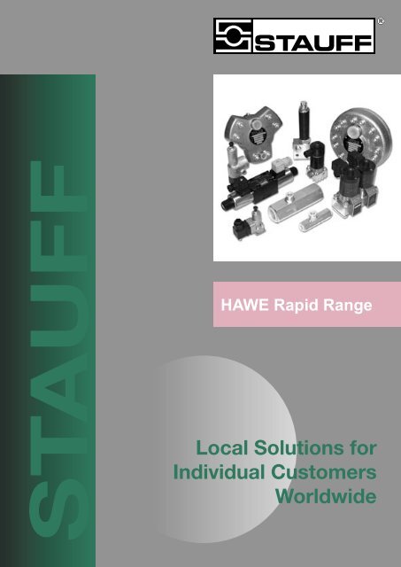
STAUFF<br />
<strong>HAWE</strong> <strong>Rapid</strong> <strong>Range</strong><br />
Local Solutions for<br />
Individual Customers<br />
Worldwide
Hawe <strong>Rapid</strong> <strong>Range</strong><br />
Contents<br />
<strong>HAWE</strong> <strong>Rapid</strong> <strong>Range</strong><br />
Page<br />
Radial Piston Pumps 3<br />
Directional Spool Valves 4<br />
Directional Seated Valves 5-7<br />
Pressure Switches 7<br />
Pressure Relief Valves 8<br />
Pilot Operated Check Valves 9<br />
Counter Balance Valves 9<br />
Cartridge Type Check Valve 10<br />
Pressure Reducing Valve 11<br />
Throttle Valves 12<br />
Inline Filters 12<br />
CETOP3 - Directional Control Valves 13<br />
Flow Dividers 14<br />
Line Rupture Valves 15<br />
For other products in the <strong>HAWE</strong> complete range consult your <strong>Stauff</strong> representative.<br />
2
<strong>HAWE</strong> <strong>Rapid</strong> <strong>Range</strong><br />
Radial Piston Pumps<br />
Radial piston pumps comprise pumping elements radially mounted in a pump housing driven by an eccentric shaft.<br />
This permits the pump to be mounted “in-tank” as a power pack installation or as an externally mounted pump with<br />
the normal suction and delivery lines. Pumps can be supplied in a number of configurations with the numbers of<br />
pistons (pumping elements) ranging from 1 piston through to 42 pistons. Pumps may be delivered as a single outlet<br />
unit or in a variety of multiple outlet configurations depending on the specific requirements of the application.<br />
Dual stage pumps combine a radial piston pump with a directly-coupled low-pressure gear pump. This, combined<br />
with a dual-stage valve, is useful in press applications where quick approach but slow pressing is needed.<br />
Single and Multiple Outlet Pumps<br />
Available as:<br />
P max:<br />
Q max:<br />
individual pump<br />
pump complete with motor<br />
hydraulic power pack<br />
700 bar<br />
91.2 l/min<br />
displ = 64.18cm 3 /rev<br />
R series pumps have ball bearings and the RG series of pumps have bushed bearings to increase the service life<br />
of the pump in extreme operating conditions.<br />
The numbers in the table indicate the flow in litres per minute at a pump speed of 1450 RPM for a single outlet pump.<br />
D es i g n<br />
N o . o f<br />
c y l i n d er s<br />
Pm ax<br />
700 b ar<br />
Pm ax<br />
550 b ar<br />
Pm ax<br />
450 b ar<br />
Pm ax<br />
250 b ar<br />
7631<br />
2 R 0.18<br />
R 0.28<br />
R 0.43<br />
R0.92<br />
7631<br />
3 R 0.27<br />
R 0.42<br />
R0.64<br />
R 1.35<br />
7631<br />
5 R 0.46<br />
R 0. 7 R1.08<br />
R 2.27<br />
Pm ax<br />
160 b ar<br />
6010<br />
1 R ( G) 0. 3 R ( G) 0.<br />
5 R ( G) 0.<br />
8 R ( G) 1.<br />
7 R(G) 2.<br />
2<br />
6010<br />
2 R ( G) 0. 6 R ( G) 1.<br />
0 R ( G) 1.<br />
6 R ( G) 3.<br />
3 R(G) 4.<br />
4<br />
6010<br />
3 R ( G) 0. 9 R ( G) 1.<br />
5 R ( G) 2.<br />
5 R ( G) 5.<br />
1 R(G) 6.<br />
5<br />
6011<br />
5 R ( G) 1. 4 R ( G) 2.<br />
6 R ( G) 4.<br />
2 R ( G) 8.<br />
3 R(G) 10.<br />
9<br />
6011<br />
7 R ( G) 2. 1 R ( G) 3.<br />
7 R ( G) 5.<br />
8 R ( G) 11.<br />
8 R(G) 15.<br />
3<br />
6012<br />
10<br />
R ( G) 2. 7 R ( G) 5.<br />
3 R ( G) 8.<br />
2 R ( G) 16.<br />
8 R(G) 21.<br />
7<br />
6012<br />
14<br />
R ( G) 4. 0 R ( G) 7.<br />
4 R ( G) 11.<br />
6 R ( G) 23.<br />
5 R(G) 30.<br />
4<br />
6014<br />
20<br />
R ( G) 6. 1 R ( G) 11.<br />
0 R ( G) 17.<br />
4 R ( G) 35.<br />
0 R(G) 43.<br />
4<br />
6014<br />
28<br />
R ( G) 8. 0 R ( G) 15.<br />
0 R ( G) 23.<br />
0 R ( G) 47.<br />
0 R(G) 60.<br />
8<br />
6016<br />
42<br />
R ( G) 12. 7 R ( G) 22.<br />
0 R ( G) 34.<br />
5 R ( G) 70.<br />
0 R(G) 91.<br />
2<br />
Multiple outlet pumps provide great flexibility for system designers. The outputs from each piston may be directed<br />
as a separate flow or groups of pistons may be combined to give specific flows. There are a great number of<br />
possible combinations and when used to give specific individual flows, the high efficiency of the piston pump<br />
permits greater accuracy than other types of flow dividers. Complete information on the possibilities is available<br />
from the local <strong>Stauff</strong> branch.<br />
Two stage pumps<br />
These consist of a high pressure R series pump directly coupled to a low pressure gear<br />
pump. The low pressure pump may be a Group 1, 2 or 3 metric pump in a range of<br />
displacements and the maximum flow possible from the largest Group 3 pump is 135 l/min.<br />
For the possible combinations of high pressure and low pressure flows, contact your <strong>Stauff</strong><br />
branch. Two stage valve assemblies are also available to make high/low applications such<br />
as hydraulic presses a simple matter.<br />
3
Hawe <strong>Rapid</strong> <strong>Range</strong><br />
Directional Spool Valves type SG and SP, 2/2-, 4/2-, 3/2- and 4/3 way<br />
The SG directional spool valves are for pipe<br />
mounting and the SP valves are for manifold<br />
mounting. They are widely used to control the<br />
direction of movement of hydraulic motors and<br />
cylinders. The wide range of spool configurations<br />
and the sturdy design make the valves suitable<br />
for applications in both mobile and fixed installations.<br />
The SG type also has available an optional<br />
integrated pressure relief valve. Another option for<br />
the valves is enlarged ports and control grooves<br />
to minimise pressure surges.<br />
Pmax: 200 ... 400 bar<br />
Qmax: 12 ... 100 l/min<br />
Actuation options<br />
Solenoid -<br />
12V & 24V DC<br />
230V AC<br />
Manual -<br />
with spring centering<br />
with detent<br />
Roller head -<br />
Pin head -<br />
Pressure -<br />
Hydraulic pilot, 12 - 20 bar<br />
Pneumatic pilot, 5 - 10 bar<br />
Basic Type and Size<br />
Individual valve for Manifold Flow Operating Pressure, Pmax (bar), for actuation Port Sizes<br />
pipe connection mount valve Q max (l/m) Solenoid Manual Mechanical Pressure BSPP<br />
SG 0<br />
12<br />
200<br />
400<br />
400<br />
400<br />
¼”, 3/8”<br />
SG 1 SP 1 20 200 400 400 400 3/8”<br />
SG 2<br />
30<br />
315<br />
400<br />
400<br />
400<br />
3/8”<br />
SG 3 SP 3 50 315 400 400 400 ½”<br />
SG 5<br />
100<br />
200<br />
400<br />
315<br />
400<br />
1”<br />
Diagrammatic Symbols<br />
SG<br />
SP<br />
G C D E N W R V<br />
2<br />
Z U 2<br />
individual valve for individual valve for<br />
pipe connection manifold mounting<br />
O<br />
a<br />
B P B<br />
A R A<br />
a a a<br />
P<br />
O<br />
O<br />
O<br />
R<br />
b<br />
b<br />
B A R P<br />
B A R P<br />
L F H Y S X 2<br />
with pressure relief valve<br />
2. only size 2, 3 and 5<br />
P<br />
R<br />
Actuations<br />
Manual Solenoid Mechanical Pressure Dual Actuation<br />
Spring Detent Roller Pin Pneumatic Hydraulic Pneumatic/ Hydraulic/<br />
return<br />
head head<br />
manual manual<br />
AK CK ME / MD MU RE / RD BE / BD NE / ND NU NM KD KM<br />
Order Example SG 1 G - AK<br />
Manually operated, spring centered single spool valve, size 1 with screwed ports, flow path G.<br />
4
<strong>HAWE</strong> <strong>Rapid</strong> <strong>Range</strong><br />
Valves<br />
The Hawe range of valves encompasses a wide variety of functions and sizes. Listed here are some of the more<br />
common valves. For full information, consult your local <strong>Stauff</strong> branch<br />
Directional Seated Valves<br />
Pmax: 320 ... 700 bar<br />
Qmax: 6 ... 120 l/min<br />
These zero leakage, directional seated valves use spring<br />
loaded balls as the valve elements. The units are subplate<br />
mounted and are available with a range of different<br />
actuations. This subplate may be fitted with screwed ports<br />
for pipe mounting. Some optional features such as<br />
restrictors or check valves are available in the subplates<br />
to improve the versatility of these valves. 2/2- and 3/2-way<br />
basic versions are available in a single body. 3/3-, 4/2-<br />
and 4/3 way valves are made by combining various functions<br />
on a common subplate.<br />
The indicated flow path on the valve must be followed for<br />
correct functioning.<br />
Actuation Options<br />
Solenoid–<br />
12V & 24V DC<br />
230V AC<br />
Pressure –<br />
Hydraulic pilot<br />
Pneumatic pilot<br />
Mechanical –<br />
Roller<br />
Pin<br />
Manual –<br />
Hand lever<br />
Turn knob<br />
Product Code<br />
Actuation<br />
GR2 - 3<br />
Size<br />
Function symbol<br />
Port<br />
Flow Solenoid Actuated Threads<br />
Valve Size Qmax (l/m) 24V DC 230V AC Pressure Actuated Mechanically Actuated Manually Actuated BSPP<br />
G WG H P K T F D<br />
0 6 300......500 500 500 - - Pmax 500 1/4”<br />
1 12 Pmax 700 Pmax 700 Pmax 700 Pmax 700 1/4” & 3/8”<br />
2 25 Pmax 500 Pmax 700 Pmax 700 Pmax 700 3/8” & 1/2”<br />
3 65 Pmax 400 Pmax 400 Pmax 400 Pmax 400 - - 1/2” & 3/4”<br />
4 120 Pmax 400 Pmax 400 - - - - - - 3/4” & 1”<br />
Actuation Methods<br />
Solenoid Pressure Mechanical Manual<br />
hydraulic pneumatic roller pin hand lever turn knob<br />
G WG H P K T F D<br />
Voltage<br />
& Current<br />
12VDC<br />
24VDC<br />
110VAC<br />
230VAC<br />
Solenoid<br />
Coding<br />
G12<br />
G24<br />
WG110<br />
WG230<br />
Function Symbols<br />
Subplate Options<br />
5
Hawe <strong>Rapid</strong> <strong>Range</strong><br />
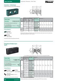
Directional Seated Valves type BVG, BVE and BVP<br />
The directional cone seated valves, types BVG,<br />
BVE and BVP are 2/2- and 3/2-way directional<br />
valves which are available in three sizes. The<br />
design permits flow in any direction at full system<br />
pressure.<br />
The valves may be connected directly via pipes<br />
(type BVG) or mounted on customer supplied<br />
manifolds (type BVP and BVE). Type BVE is<br />
available only with solenoid operation but hydraulic,<br />
pneumatic or manual operation is available<br />
for the other models permitting a wide range of<br />
applications.<br />
Pmax: 250 ... 400 bar<br />
Qmax: 12 ... 50 l/min<br />
Actuation Options<br />
Solenoid -<br />
12V & 24V DC<br />
230V AC<br />
Pressure -<br />
Hydraulic pilot, 24 - 320 bar<br />
Pneumatic pilot, 3.5 - 15 bar<br />
Manual -<br />
BVG 1 valve only<br />
Basic Type and Size<br />
Individual valve for Manifold Flow Oper. Press. Port sizes Symbol<br />
pipe connection mount valve Q max (l/m) P max (bar) (BSPP) R S Z<br />
A,B,C 2<br />
BVG 1, BVG 2 BVP 1 12/20 400 / 250 1 ¼”, 3/8”<br />
BVG 3 BVP 3 50 320 ½”<br />
BVE 3 4 70 400 ½<br />
1. with electrical actuation GM.. and WGM<br />
2. with type BVG<br />
3. only size 1 and only with solenoid actuation<br />
4. cartridge valve, also available with connection block for pipe connection<br />
G 3 D 3<br />
Other options<br />
individual valve with orifice in one port<br />
2/2-way valve with bypass check valve<br />
twin valve version<br />
BVP 1 with ex-proof design<br />
additional elements to make 4/3 valve<br />
Order Example BVG 1 - R - 3/8 - WG230<br />
Size 1 BVG valve with 3/8” BSPP ports, flow path R (2/2-way function), 230V AC solenoid operation.<br />
BVP 3 - Z - H<br />
Size 3 BVP manifold mounted valve, flow path Z (3/2-way function), hydraulic pilot operation.<br />
Examples<br />
Type BVG for pipe connection<br />
(solenoid operated - see order example)<br />
Type BVP for manifold mounting<br />
(hydraulic pilot operation - see order example)<br />
6
<strong>HAWE</strong> <strong>Rapid</strong> <strong>Range</strong><br />
Directional Seated Valves type WH<br />
These zero leakage, directional seated valves use spring<br />
loaded balls as the valve elements. These compact valves<br />
are manifold or sub-plate mounted. Both 2/2 and 3/2 configurations<br />
are available and 3/3 and 4/3 functions are<br />
achieved by combining multiple valves on one manifold.<br />
The indicated flow path on the valve must be followed for<br />
correct functioning.<br />
Pmax: 350 ... 450 bar<br />
Qmax: 8 ... 30 l/min<br />
Actuation Options<br />
Solenoid -<br />
12V & 24 V DC<br />
230V AC<br />
Basic type Flow Oper. Pressure Port Size<br />
and size Qmax (l/m) Pmax (bar) (of optional subplate)<br />
WH1 8 450 1/4” BSPP<br />
Subplate Options<br />
Part No. Size & Type Port Size<br />
WH1-1/4-2/2 Size 1, 2/2 1/4” BSPP<br />
WH1-1/4-3/2 Size 1, 3/2 1/4” BSPP<br />
Valve Symbols<br />
D Q F E H N M R<br />
Order Example WH1F-G24<br />
Size 1 WH valve with”F” flow pattern and 24V DC solenoid operation, without sub-plate.<br />
Pressure Switches type DG<br />
Pressure switches are electro-hydraulic devices where<br />
a spring-loaded piston sensing hydraulic pressure operates<br />
an electrical switch. The pressure setting is a<br />
simple spring adjustment. The electrical signal can<br />
be used for switching on or off an ancillary component,<br />
for initiating another part of the operating cycle, and for<br />
many other applications.<br />
The normal switches have a hysteresis of between 8<br />
... 20%. This means that the pressure will have to drop<br />
by that much below the set point before the switch resets<br />
to the original mode. The exception is the electronic type, DG 5 E which has provision to<br />
set two independent switch points.<br />
Pmax: 4 ... 700 bar<br />
Design Options<br />
Female screwed port<br />
Male threaded connection<br />
Manifold mount<br />
Dial faced type<br />
Electronic type<br />
Dual switches<br />
Basic type Brief Description Pressure Adj. Max. Pressure Connection Symbol<br />
and Size<br />
<strong>Range</strong> (bar)<br />
(Pmax) Thread (BSPP)<br />
DG 1R adjustment by turn-knob 20 ... 600 600 ¼”F or ½”M<br />
on the dial face<br />
DG 33 20 ... 700 700<br />
DG 34 Compact design for 100 ... 400 700<br />
manifold mounting<br />
DG 35 Adj. by set screw 20 ... 250 700 ¼” M or ¼”F<br />
DG 365 12 ... 170 700<br />
DG 36 4 ..... 12 700<br />
1<br />
3<br />
2<br />
DG 5 E Electronic pressure switch 0 ... 250 400 ¼” F<br />
with two switch points 0 ... 400 600<br />
7
Direct-acting Relief and Sequence Valves type MV, SV, etc.<br />
Direct-acting relief valves limit the maximum pressure<br />
in a hydraulic system thus safeguarding<br />
against excessive pressure.<br />
Sequence valves maintain a constant pressure differential<br />
between the inlet and outlet of the valve.<br />
The valves are available with screwed ports for pipe<br />
mounting, as a manifold mount valve, or as a cartridge<br />
type valve. Various maximum pressure settings<br />
are available to allow the system designer<br />
maximum flexibility.<br />
Hawe <strong>Rapid</strong> <strong>Range</strong><br />
Pmax: 700 bar<br />
Qmax: 5 ... 160 l/min<br />
Adjustment Options<br />
Tool adjustable<br />
Manually adjustable<br />
Type Approval<br />
TUV approved version is<br />
available for use as<br />
accumulator safety<br />
valves.<br />
Basic Types and General Description<br />
relief relief valve & sequence relief valve cross-line relief relief valve with reverse relief valve &<br />
v alve valve<br />
manifold mount<br />
free-flow check valve sequence valve.<br />
MV 1 5 MVS 1 5 / MVG 3 MVE 5 SV 1 MVP 5 DMV 1 MVCS 2 / MVGC 3 SVC 1 MVB 1 4<br />
Notes<br />
1. only sizes 4, 5, 6 and 8<br />
2. only sizes 4, 5,and 6<br />
3. only size 13 and 14<br />
4. other type kits are available<br />
5. TUV approval available , sizes 4, 5 and 6<br />
Maximum permissible pressure in “R” outlet port<br />
MV 20 bar MVS, MVG, MVE 500 bar<br />
MVB 200 bar MVCS, MVGC 500 bar<br />
DMV 350 bar SV, SVC 500 bar<br />
Valve Style<br />
MV, MVS, MVG - 90° configuration with screwed ports MVE - Cartridge type valve MVB - Assembly kit for integral manifolds, etc.<br />
SV, SVC - In-line valve for straight pipe installation MVCS, MVGC - 90° configuration with screwed ports<br />
DMV - Cross-line relief valves with screwed ports<br />
All valves are adjustable but the “R” in the code indicates that there is a<br />
hand adjustable knob eliminating the need for tools to adjust the settings<br />
Maximum Pressure and Flow Ratings<br />
A letter is used to indicate the maximum pressure setting of the valve. In the table below, the maximum pressure setting and also the<br />
maximum flow are set out against the available valve sizes. The first figure is the maximum pressure in bar and the second is the maximum<br />
flow in l/min. The possible BSPP port sizes are shown for those valves with screwed ports. In the order code, a number denotes the<br />
screwed port size: 1 = 1/4”, 2 = 3/8”, 3 = 1/2”, 4 = 3/4” and 5 = 1”.<br />
Size 13 14 4 5 6 8<br />
Order Example<br />
8<br />
H: 700/5 N: 50/8 F: 80/20 F: 80/40 F: 80/75 E: 160/160<br />
M: 200/8 E: 160/20 E: 160/40 E: 160/75 C: 315/160<br />
H: 400/8 C: 315/20 C: 315/40 C: 315/75<br />
B: 500/20 B: 500/40 B: 500/75<br />
A: 700/12 A: 700/20 A: 700/40<br />
1/4” 1/4” 1/4” 3/8” 1/2” 3/4”<br />
3/8” 1/2” 3/4” 1”<br />
MVS 52 BR<br />
Relief or sequence valve with 90° configuration, screwed ports 3/8” BSPP (Code 2), pressure range up to 500<br />
bar (Code B), with manually adjustable pressure setting (Code R).<br />
MVP 13 HR<br />
Manifold mount valve, size 13, pressure range manually adjustable (Code R) between 20 and 700 bar (Code H).
<strong>HAWE</strong> <strong>Rapid</strong> <strong>Range</strong><br />
Pilot Operated Check Valves type RH and DRH<br />
The pilot operated check valves type RH and DRH<br />
are used for blocking one or two pressure lines, as<br />
pilot operated drain valves, or as idle circulation valves<br />
to unload a pump or other part of a system. As an<br />
option, the valves may be equipped with a pre-release<br />
to prevent decompression surges in the event<br />
of high pressure and high flow. The type DRH has<br />
many variations and options such as in-line design,<br />
manifold mounting design, shock valves, relief valves<br />
to prevent slow pressure build-up, and a leakage<br />
port to prevent unintended opening of the valve due<br />
to pressure rises caused by leaking spool valves.<br />
All components are steel.<br />
Pmax: 400 ... 700 bar<br />
Qmax: 15 ... 160 l/min<br />
Design Options<br />
with or without decompression<br />
function<br />
in-line design<br />
manifold mount design<br />
integral relief valve<br />
leakage oil port<br />
selectable pressure range<br />
Basic Type Flow Qmax Pressure Release Ratio BSPP Ports<br />
& Size (l/min) Pmax (bar) P(A or B) / PZ Service Ports Pilot Port<br />
RH 1 15 700 2.7 1/4” 1/4”<br />
RH 2 35 700 3 3/8” 1/4”<br />
RH 3V 55 500 5 - 8 1/2” 1/4”<br />
RH 4V 100 500 6 - 11 3/4” 1/4”<br />
RH 5V 160 500 7 - 13 1” 1/4”<br />
DRH 1 16 500 2.5 1/4” -<br />
DRH 2 30 500 2.5 3/8” -<br />
DRH 3 60 500 2.5 1/2” -<br />
DRH 4 90 400 2.5 3/4” -<br />
DRH 5 140 400 2.5 1” -<br />
N.B. Models with the letter “V” indicate that there is a decompression function in the valve.<br />
Counterbalance valves type LHK<br />
Counterbalance or load-holding valves are pressure<br />
valves which act on the return flow side of double acting<br />
cylinders or motors. They stop the load running away<br />
allowing controlled lowering of a cylinder load or a motor<br />
driven load such as a winch.<br />
The valves are available as single valves (see LHT 33 P-<br />
11) or as double acting valves (see LHK 44 G-21).<br />
All components are steel.<br />
Pmax: 360 ...450 bar<br />
Qmax: 250 lpm<br />
Design Options<br />
In-line mounted<br />
Flange mounted<br />
Cartridge valve<br />
Internal relief valves<br />
Shuttle valves for double<br />
acting valves<br />
Basic type Flow Oper. Press. Pilot ratio Ports<br />
and size Qmax lpm Pmax bar (BSPP)<br />
LHK 22 20 400 1 : 4.6 3/8”<br />
LHK 33 60 360 1 : 4.4 1/2”<br />
LHK 44 100 350 1 : 4.4 3/4”<br />
LHDV 33 80 420 1 : 8 1/2”<br />
LHT 2 20 400 1 : 8 1/4”<br />
LHT 3 130 450 1 : 7 1/2”<br />
LHT 5 250 450 1 : 6 1”<br />
For further details, refer to Leaflets D7100, D7770 and D7918<br />
9
Hawe <strong>Rapid</strong> <strong>Range</strong><br />
Cartridge Pilot operated Check Valves type CRH and RHC<br />
Pilot operated check valves are used in hydraulic circuits<br />
where the directional control valves exhibit normal spool<br />
leakage. They can also be used as hydraulically operated<br />
drain valves or as “idle circulation” valves.<br />
Q max: 80 l/min (CRH)<br />
200 l/min (RHC)<br />
P max: 500 bar<br />
The type CRH valves are pilot operated cartridge type<br />
valves and the type RHC valves are designed as screw-in<br />
valves. The RHC valves are available with a decompression<br />
(pre-release) function for high pressure and high flow<br />
applications. The mounting ports are of a simple, easilymachined<br />
design. Ask for machining details.<br />
Optional Pilot Ratios<br />
available<br />
Option: decompression<br />
(pre-release)<br />
Basic type Flow (Qmax) Op. Press. Release Ratio Mounting<br />
& size l/min P max (bar) P A<br />
: P Z<br />
thread<br />
CRH 1 30 500 2.6 M16 x 1.5<br />
CRH 2 50 500 2.6 M20 x 1.5<br />
CRH 3 80 500 2.5 M24 x 1.5<br />
RHC 1 15 500 2.6 M16 x 1.5<br />
RHC 2 25 500 2.6 M20 x 1.5<br />
RHC 3 55 500 2.5 M24 x 1.5<br />
RHC 4 100 500 2.5 M30 x 1.5<br />
RHC 5 150 400 2.8 M36 x 1.5<br />
RHC 6 200 400 2.5 M42 x 1.5<br />
RHC43/3V 100 500 4.3 M36 x 1.5<br />
RHC53/4V 150 400 4.3 M38 x 1.5<br />
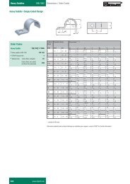
Cartridge & In-Line Check Valves, type RK<br />
Check valves are used to block flow in one direction and<br />
permit free flow in the opposite direction. The RK check<br />
valve is a spring-loaded, ball seated type which, by<br />
design, is tolerant of contamination.<br />
The mounting ports are easily machined for the screw-in<br />
RK type. Housings for in-line installation are available on<br />
request or easily manufactured. Installation tools are also<br />
available to ensure correct assembly of the insert.<br />
Q max: 6 ... 120 l/min<br />
P max: 400 ... 700 bar<br />
Design option:<br />
screw-in valve insert<br />
valve insert in<br />
housing for in-line<br />
installation<br />
Size Thread Flow Pressure Part No.<br />
BSPP Q max (l/m) Pmax (bar) insert c/w housing<br />
0 1/8” 10 700 RK0 RK0G<br />
1 1/4” 20 700 RK1 RK1G<br />
2 3/8” 50 700 RK2 RK2G<br />
3 1/2” 80 500 RK3 RK3G<br />
4 3/4” 120 500 RK4 RK4G<br />
Order Example<br />
RK 1<br />
screw-in check valve, type RK, size 1<br />
RK 2 G<br />
RK check valve, size 2, in housing for in-line installation<br />
N.B. Extraction tools for the inserts are available<br />
10<br />
RK..G
<strong>HAWE</strong> <strong>Rapid</strong> <strong>Range</strong><br />
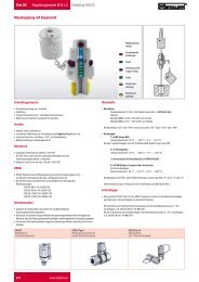
Pressure Reducing Valves type CDK<br />
Pressure reducing valves in a hydraulic circuit maintain a<br />
constant outlet pressure even though the input pressure<br />
is higher and variable. They are used to supply a secondary<br />
circuit with lower pressure fluid without affecting the<br />
higher pressure in the primary circuit.<br />
The CDK valve is a directly controlled type and is a seated<br />
type which has no leakage when closed and therefore no<br />
need of a drain line. A reversal of flow is possible up to<br />
2 x Qmax. The valve stocked is a pipe mounted version<br />
but cartridge types are also available.<br />
Q max: 15 l/min<br />
P max:<br />
inlet - 500 bar<br />
outlet - 400 bar<br />
Adjustment Options<br />
Tool adjustable<br />
Manually adjustable<br />
Basic Types and General Description<br />
cartridge valve pipe connection version manifold mounting version<br />
with optional pressure switch<br />
CDK 3 - .. CDK 3 - .. - 1/4 - DGS. CDK 3 - .. - P Pressure <strong>Range</strong><br />
Pmax A<br />
Tapped Ports<br />
(BSPP)<br />
P<br />
A<br />
.. -08 400 bar<br />
.. - 1 300 bar<br />
.. - 2 200 bar<br />
.. - 5 130 bar<br />
1/4” for the pipe<br />
mounted version<br />
Order Example<br />
CDK 3 - 1 - 1/4 - 250<br />
Pressure reducing<br />
valve, pipe connection<br />
(1/4” BSPP),<br />
pressure range 30 to<br />
300 bar (Code 1), tool<br />
adjustable version,<br />
preset to 250 bar<br />
CDK 3 - 1 - 180<br />
Pressure reducing<br />
valve, cartridge type,<br />
pressure range<br />
30 - 300 bar (Code 1),<br />
tool adjustable version<br />
preset to 180 bar.<br />
Unit dimensions<br />
Basic type (cartridge valve)<br />
Type CDK 3, CDK 32, and CDK 35<br />
11
Hawe <strong>Rapid</strong> <strong>Range</strong><br />
Throttle type Flow Valves, Q, QR, QV and FG<br />
Throttle valves are flow control valves and are used to limit<br />
the flow in accumulator and control circuits. They feature a<br />
slotted throttle section which is much less sensitive to<br />
contamination than annular type throttle valves.<br />
The valves Q, QR and QV are available in five sizes covering<br />
flow rates up to 120 l/min. The fine throttles, type FG, are<br />
preferred for applications where the switching speeds of<br />
directional valves have to be adjusted, the prevention of<br />
pressure surges is required, or for the damping of oscillations,<br />
etc.<br />
Pmax: 300 ... 400 bar<br />
Qmax: 0 ... 80 l/min<br />
Design Options<br />
cartridge design<br />
individual valve for pipe<br />
mounting<br />
90° housing<br />
banjo bolt<br />
swivel housing<br />
The throttle effect can be adjusted by the thread, altering the<br />
effective slot length and the valves are only available as “tool<br />
adjustable” versions.<br />
Basic Type Flow Pressure Schematic Drawings<br />
Symbol<br />
& Size Qmax (l/m) Pmax (bar) of the devices<br />
Standard Banjo bolt Swivel housing<br />
screw-in throttle<br />
FG, Q<br />
FG, FG1, FG2 0.15 300<br />
FG1, QR<br />
Q20, QR20, QV20 12 400<br />
Q30, QR30, QV30 25 400<br />
FG2, QV<br />
Q40, QR40, QV40 50 400<br />
Q50, QR50, QV50 90 400<br />
Q60, QR60, QV60 120 400<br />
Hydraulic Accessories<br />
- In-line filters<br />
Many devices such as pressure gauges, pressure<br />
switches, accumulators, etc., are installed in hydraulic<br />
systems by means of fittings. To protect the device<br />
from unwanted contamination, in-line filters can be<br />
employed.<br />
Pmax: 350 ... 700 bar<br />
Design Options<br />
In-line housing<br />
Screw-in version<br />
Hawe has two types of filters for this purpose - a coarse<br />
screen for such material as drilling swarf, and a wire<br />
mesh filter with a finer micron rating which is only for<br />
low flow applications. The screen is available as a<br />
screw-in disc for fitting to either a machined port or a<br />
housing body.<br />
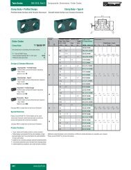
StrainerDisc Thread Size Example of mounting Screw-in in a Symbol Housing BSPP<br />
in a housing<br />
threaded port<br />
female / female<br />
HFC1/4<br />
1/4” BSP<br />
SHF1/4<br />
1/4”BSPP<br />
HFC3/8<br />
3/8” BSP<br />
SHF3/8<br />
3/8” BSPP<br />
HFC1/2<br />
1/2” BSP<br />
SHF1/2<br />
1/2” BSPP<br />
N.B. Available on request are the fine wire mesh filters (100µm) and the part number is HFC...F with the BSP size<br />
inserted.<br />
12
<strong>HAWE</strong> <strong>Rapid</strong> <strong>Range</strong><br />
Directional Control Valves, Solenoid Operated, CETOP 3 mounting<br />
CETOP 5 valves are available on request<br />
Q max: 60 l/min<br />
Hawe solenoid operated directional<br />
control valves offer long, reliable life<br />
with optimum performance.<br />
A range of spool variations allows<br />
the system designer to select a<br />
valve to suit the requirements of<br />
the application. The subplates for<br />
mounting the valve are also available in<br />
either a side ported or bottom ported single<br />
mount version or multiple station manifold<br />
versions.<br />
P max: 350 bar P, A, B ports<br />
210 bar T port<br />
Design : wet armature design<br />
with easily replace<br />
able coils<br />
Current: AC & DC options<br />
Voltage: 12, 24 V DC,<br />
110, 230 V AC<br />
The solenoid coils are all DC windings. The AC<br />
versions have rectifiers in the Hirschmann plugs<br />
to convert the AC to DC.<br />
Basic type Voltage and Current Coding<br />
SWPN 2 12VDC G12<br />
24VDC<br />
G24<br />
110VAC<br />
WG110<br />
230VAC<br />
WG230<br />
Order Example<br />
To the basic SWPN 2, add the spool<br />
required and the voltage and current<br />
type to get the valve part number.<br />
SWPN 2-H-G24<br />
CETOP3 valve with a “H” spool and with 24VDC input power.<br />
SWPN 2-L-WG230<br />
CETOP3 valve with a “L” spool and with 230V AC input power.<br />
Subplates & Manifolds<br />
Subplates in aluminium and steel are available to mount the CETOP3 valves, with either side ports or a combination<br />
of side and bottom ports. A bolt kit incorporating 4 socket head cap screws is also available to suit the valve.<br />
In addition, blanking plates to seal a subplate or manifold when the valve is removed are also available.<br />
Manifold blocks in steel or aluminium are available on request in both series and parallel design. Sandwich plates<br />
with relief, throttle and check functions are available.<br />
Part No.<br />
SSPC3B<br />
SSPC3B-S<br />
SSPC3S<br />
SSPC3S-S<br />
SBPC3S<br />
SBKC3<br />
Description<br />
Aluminium subplate, P & T ports on bottom, A & B ports on the side<br />
Steel subplate, P & T ports on bottom, A & B ports on the side<br />
Aluminium subplate, all ports side entry<br />
Steel subplate, all ports side entry<br />
Aluminium blanking plate<br />
Bolt kit, cap screws, M5 x 30mm x 4 pieces<br />
13
Flow Dividers type TQ and TV<br />
Hawe <strong>Rapid</strong> <strong>Range</strong><br />
The flow dividers type TQ divide (collect) total flow entering (exiting)<br />
port C. The distribution is independent of working pressure at ports A<br />
and B, and may be divided equally or unequally in predetermined<br />
portions. The flow divider type TV features priority division, i.e. variable<br />
flow entering port C is divided where partial flow QA, through port A,<br />
is kept constant and the residual flow, QB, exits port B. As soon as<br />
one actuators movement is stopped the flow to the other is either<br />
reduced to a minimal flow (type TQ) or completely reduced to leakage<br />
flow (type TV). It is possible to overcome this design feature by creating<br />
flow via a pressure limiting valve.<br />
14<br />
Further Information<br />
- Flow divider (flow distributor) type TQ D 7381<br />
- Flow divider type TV D 7394
<strong>HAWE</strong> <strong>Rapid</strong> <strong>Range</strong><br />
Line rupture safety valves type LB<br />
The line rupture safety valves type LB are check valves. They are available as<br />
screw-in valves or with housing for in-line installation. The line rupture safety<br />
valves are best installed directly on the actuator (cylinder) which is to be<br />
safeguarded. This will prevent an uncontrollable, accelerated movement (drop)<br />
of a loaded cylinder when the hydraulic back-pressure is lost as a result of a<br />
rupture of the pressurized line or pipe connection.<br />
When the flow through the valve increases above the pre-set limit, the flow<br />
forces will exceed the opposing spring force and the valve will block the flow<br />
immediately. The valve element in these valves is a shim.<br />
There are two different versions available. One valve design completely blocks<br />
the flow when actuated, whereas the other one allows a minimum flow (via<br />
an orifice) to slowly drop the load.<br />
Further Information<br />
Refer: D 6990<br />
Order Examples<br />
LB4C(G)-40<br />
1) Version with housing<br />
Type of housing<br />
Cartridge Type<br />
Size 4<br />
Set to 40 l/min<br />
15
HEAD OFFICE<br />
24 - 26 Doyle Avenue<br />
UNANDERRA NSW 2526<br />
P.O.Box 227<br />
UNANDERRA NSW 2526<br />
Ph: (02) 4271 1877<br />
Fax: (02) 4271 8432<br />
E-mail: info@stauff.com.au<br />
www.stauff.com.au<br />
MELBOURNE<br />
3B 14 - 16 White Street<br />
OAKLEIGH EAST VIC 3166<br />
P.O. Box 453<br />
MULGRAVE VIC 3170<br />
Ph: (03) 9543 5411<br />
Fax: (03) 9543 5422<br />
AUCKLAND<br />
Unit D 103 Harris Road<br />
EAST TAMAKI<br />
P.O. Box 58517<br />
GREENMOUNT<br />
Ph: (09) 271 4812<br />
Fax: (09) 271 4832<br />
E-mail: sales@stauff.co.nz<br />
www.stauff.com<br />
Distributed by:<br />
Australia<br />
STAUFF CORPORATION PTY LTD<br />
New Zealand<br />
STAUFF CORPORATION (NZ) LTD<br />
SYDNEY<br />
27B Davis Road<br />
WETHERILL PARK<br />
NSW 2164<br />
P.O. Box 7180<br />
WETHERILL PARK DC<br />
NSW 2164<br />
Ph: (02) 9725 2733<br />
Fax: (02) 9725 2744<br />
BRISBANE<br />
463 Boundary Road<br />
RICHLANDS QLD 4077<br />
P.O. Box 20<br />
RICHLANDS QLD 4077<br />
Ph: (07) 3217 0444<br />
Fax: (07) 3217 0300<br />
ADELAIDE<br />
1/3 Endeavour Drive<br />
PORT ADELAIDE SA 5015<br />
P.O. Box 208<br />
PORT ADELAIDE SA 5015<br />
Ph: (08) 8341 2260<br />
Fax: (08) 8341 1604<br />
STAUFF<br />
STAUS-HRR-ENG-06/2007<br />
E & OE