

The GRC-9 Part 2… - VMARSmanuals
The GRC-9 Part 2… - VMARSmanuals
The GRC-9 Part 2… - VMARSmanuals

You also want an ePaper? Increase the reach of your titles
YUMPU automatically turns print PDFs into web optimized ePapers that Google loves.
<strong>The</strong> VMARS Newsletter Issue 33<br />
<strong>The</strong> <strong>GRC</strong>-9 <strong>Part</strong> 2,<br />
the journey continues….<br />
Mike Hoddy, G0JXX<br />
<strong>The</strong> Transmitter, Power Supplies and problems.<br />
In <strong>Part</strong> One I wanted to give a flavour of the <strong>GRC</strong>-9 as a good<br />
entry-level rig and focussed mainly on the receiver. In this<br />
part I want to look at the transmitter, a suggested power<br />
supply and problems that may arise when using the rig.<br />
Incidentally the power supply described here is one I put<br />
together to carry out testing and the final version will be more<br />
robust but please do take care if copying any circuits as I can<br />
accept no responsibility for shocks/swearing or death, don't<br />
forget there is at least 500V floating around - take care and<br />
keep one hand in your pocket!! Even switched off the<br />
capacitors carry a bite. If you have better versions send<br />
them into the Editor as we are always looking for ideas to get<br />
round the perennial problem of powering up vintage rigs.<br />
<strong>The</strong> <strong>GRC</strong>-9 transmitter is a fairly conventional master<br />
oscillator, buffer amplifier / doubler and power amplifier design<br />
with low - level modulation. It is based on the 3A4 valve (2.8V<br />
heater.) using three for the MO, BA and modulator with a<br />
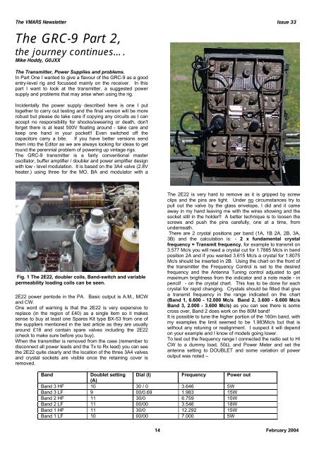
Fig. 1 <strong>The</strong> 2E22, doubler coils, Band-switch and variable<br />
permeability loading coils can be seen.<br />
2E22 power pentode in the PA. Basic output is A.M., MCW<br />
and CW.<br />
One word of warning is that the 2E22 is very expensive to<br />
replace (in the region of £40) as a single item so it makes<br />
sense to buy at least one Spares Kit type BX-53 from one of<br />
the suppliers mentioned in the last article as they are usually<br />
around £18 and contain spare valves including the 2E22<br />
(check to make sure before you buy).<br />
When the transmitter is removed from the case (remember to<br />
disconnect all power leads and the Tx to Rx lead) you can see<br />
the 2E22 quite clearly and the location of the three 3A4 valves<br />
and crystal sockets are visible once the retaining cover is<br />
removed.<br />
<strong>The</strong> 2E22 is very hard to remove as it is gripped by screw<br />
clips and the pins are tight. Under no circumstances try to<br />
pull out the valve by the glass envelope, I did and it came<br />
away in my hand leaving me with the wires showing and the<br />
socket still in the holder!! A better technique is to loosen the<br />
screws and push the pins carefully, one at a time, from<br />
underneath.<br />
<strong>The</strong>re are 2 crystal positions per band (1A, 1B 2A, 2B, 3A,<br />
3B) and the calculation is: - 2 x fundamental crystal<br />
frequency = Transmit frequency, for example to transmit on<br />
3.577 Mc/s you will need a crystal cut for 1.7885 Mc/s in band<br />
position 2A and if you wanted 3.615 Mc/s a crystal for 1.8075<br />
Mc/s should be inserted in 2B. Using the chart on the front of<br />
the transmitter the Frequency Control is set to the desired<br />
frequency and the Antenna Tuning control adjusted to get<br />
maximum brightness from the indicator and a note made - in<br />
pencil! - on the crystal chart. This has to be done for each<br />
crystal for rapid changing. Crystals should be fitted that give<br />
a transmit frequency in the range indicated on the chart<br />
(Band 1, 6.600 - 12.000 Mc/s Band 2, 3.600 - 6.600 Mc/s<br />
Band 3, 2.000 - 3.600 Mc/s) as you can see there is some<br />
cross over, Band 2 does work on the 80M band!<br />
It is possible to tune the higher portion of the 160m band, with<br />
my examples the limit seemed to be 1.983Mc/s but that is<br />
without any retuning or realignment. I suspect it will depend<br />
on your example and I know of models going lower.<br />
To test out the frequency range I connected the radio set to HI<br />
CW to a dummy load, 50Ω, and Power Meter and set the<br />
antenna setting to DOUBLET and some variation of power<br />
output was noted –<br />
Band<br />
Doublet setting Dial (I) Frequency Power out<br />
(A)<br />
Band 3 HF 10 30 / 0 3.646 5W<br />
Band 3 LF 9 00/0.69 1.983 15W<br />
Band 2 HF 11 30/0 6.759 15W<br />
Band 2 LF 11 00/00 3.546 18W<br />
Band 1 HF 11 30/0 12.292 15W<br />
Band 1 LF 10 00/00 7.000 5W<br />
14 February 2004
<strong>The</strong> VMARS Newsletter Issue 33<br />
Fig. 2 Transmitter flap open, showing Rx socket<br />
To gain access to the valve bases and components there is a<br />
hinged flap, which swings up to show the underside. I found<br />
that placing the Tx on it’s front was the best way to get access<br />
after removing the screws marked “A, B, C, D” around the<br />
edge - this instruction is marked on the lid itself. If you decide<br />
to place the transmitter upside down (i.e. resting the top on<br />
the bench) just be aware that the anode of the 2E22 is very<br />
close to the bench and if there is any bits of solder, washers<br />
or other conductive material underneath you may get a nasty<br />
surprise if HT is present, also if you tilt the rig back in this<br />
position there is a high chance that you will break the cap off<br />
the valve or crack the glass - I recommend you don’t do it!<br />
In figure 3 you can see the cause of the 120Ω resistance to<br />
ground on the 500V line just below the 2E22 valve base. <strong>The</strong><br />
left hand brown capacitor is a 0.01µF de-coupler from HT to<br />
ground and that had become low resistance; it produced a<br />
very lively bang and a lot of smoke. It is not easy to gain<br />
access to this capacitor without removing the tuning capacitor<br />
and a few other components. <strong>The</strong> manual gives clear<br />
instructions how to do this but, being lazy, I decided to leave<br />
the dead one in place, cut the leads and replace it on the<br />
upper side next to the 2E22, far easier if not so neat.<br />
Very helpfully, there is a Meter Socket fitted that allows easy<br />
testing of the basic voltages and anode current which can<br />
speed up fault - finding. <strong>The</strong> expected voltages are marked in<br />
a table on the case and it is worth making a note separately<br />
as the anode of the 2E22 has 500V on it and moving the Tx<br />
around when live is extremely risky!<br />
It is a safe bet that if you have bought a ‘tested’ rig you will<br />
need to check these voltages as I doubt it will have been run<br />
up on transmit even if it is working on receive. In most cases<br />
the voltages should be within a few percent (depending on<br />
what your supply voltages are) and if that is the case it’s a<br />
reasonable assumption that there is nothing major wrong.<br />
Measurement conditions in the manual are described as the<br />
transmitter is set for high power MO, CW operation with a<br />
20Ω 20Watt resistor (non-inductive) and a 70pF capacitor<br />
dummy antenna connected - I suspect in the Reel or Whip<br />
positions and using a 20KΩ/volt meter. In the DOUBLET<br />
position into a 50Ω Dummy Load and careful loading the<br />
voltages read about the same using an AVO meter.<br />
Brief circuit description and design features<br />
<strong>The</strong> basis of the circuit is a Master (or Crystal) Oscillator<br />
followed by a Buffer Amp / Doubler, modulator and PA. <strong>The</strong><br />
circuit shows a fairly standard design with no real challenges<br />
except that the supply voltages go through a relay system<br />
(K101 and K102 on the circuit diagram) and this can make<br />
tracing through voltages and signals difficult. <strong>The</strong> manual<br />
(TM11-263) is a valuable asset and until very recently I was<br />
relying on some photocopied circuits and information but I<br />
would advise getting a full copy of the manual if you can -<br />
costs are around £25 for a new one but it is a good<br />
Metering Socket<br />
pins<br />
NB (+ / - =<br />
Circuit<br />
polarity)<br />
1+ 7-<br />
PA Filament<br />
Voltage<br />
2+ 7-<br />
PA Plate<br />
Voltage<br />
PA Plate<br />
2+ 8-<br />
Current (loaded)<br />
Plate Current<br />
(unloaded)<br />
3+ 7-<br />
PA Screen Grid<br />
Voltage<br />
4+ 7-<br />
PA Suppressor<br />
Grid bias (CW)<br />
PA Suppressor<br />
4- 7+ Grid bias<br />
(Phone)<br />
5- 7+<br />
PA signal Grid<br />
bias<br />
6+ 7- Master<br />
Oscillator plate<br />
voltage,<br />
Modulator plate<br />
voltage<br />
7+ 7+ Terminal 7 is<br />
grounded to the<br />
transmitter<br />
chassis<br />
Volts<br />
+6.3<br />
+500<br />
Bands 1,2 and 3<br />
110mA maximum<br />
Less than 30mA on<br />
all bands<br />
+275 V maximum<br />
on all bands<br />
+6.3V<br />
-40V<br />
-46 to -70V<br />
+105V<br />
it is a good investment - and an interesting read if you are into<br />
this sort of stuff as it goes into very great detail.<br />
<strong>The</strong> modulator 3A4 (V105) is used for NET and side-tone<br />
operation in Standby / CW mode in the receiver. (Note: that<br />
the manual suggests that this feature can be used to test any<br />
suspect 3A4 valves). In CW mode the doubler and PA valve<br />
both have their anode and heater voltages applied and the<br />
MO anode is keyed (see ‘problems’ later). In phone mode the<br />
doubler and PA only have their HT and heater volts applied<br />
once the PTT is pressed giving an approximate delay of 2<br />
seconds before transmitting. <strong>The</strong> relay K102 utilises the<br />
presence of a small amount of grid current in the PA to<br />
energise and this is a point where problems may occur if there<br />
are alignment or loading faults as if the relay doesn’t energise<br />
then no output will be generated. It is also worth noting that<br />
the NET facility is disabled in PHONE mode - but works well<br />
in MCW and CW positions.<br />
In Use<br />
In use I found the neon indicator a good way of seeing quickly<br />
whether I had a match or not (after all, that is what it was<br />
designed to do) and generally the brighter and more balanced<br />
the glow, the greater the RF power going into the aerial.<br />
Which brings me onto one major drawback of the <strong>GRC</strong>-9. On<br />
one QSO I noticed that the other station was reporting chirp<br />
on the signal and some drift (albeit slight). On the monitor<br />
receiver the note sounded more like a Dwah-Dwit Dwah Dwit<br />
rather than a nice Dah Dit Dah Dit. My first thought was that<br />
the stabilising voltage (105V from a VR105) wasn’t happy or<br />
possibly the heater voltage may be dropping on key down.<br />
After testing the PSU under load this wasn’t the cause and I<br />
did find a design flaw. <strong>The</strong> anode of the 3A4 Master<br />
Oscillator is keyed via a relay contact (17 on K101), bad<br />
practice and I can’t think what the designers were thinking<br />
when they did that. I know the rig was primarily intended as a<br />
phone transmitter but even as a back up CW facility it didn’t<br />
make sense. That would also explain the slight drift on key<br />
down though the VFO is stable after the initial contact.<strong>The</strong><br />
only options are to a) live with it, and run the risk of not using<br />
15 February 2004<br />
0V
<strong>The</strong> VMARS Newsletter Issue 33<br />
it as much on CW (though phone is fine) or b) make A Simplified Power Supply<br />
modifications to switch another part of the circuit. This is a <strong>The</strong> circuit values are nominal and represent the state of my<br />
technical and a moral question given our general view that junk box at the time. T9 is a small 105-0-105 transformer<br />
original is best even if it wasn’t very good! As I like using CW, capable of about 60mA and I would have preferred to fit a<br />
I am looking at making removable modifications (without small choke but didn’t have one at the time. This is intended<br />
touching the appearance - that is beyond the pale) that will as a guide but realise it’s less than perfect - better ideas very<br />
allow the MO to run continuously and perhaps key the PA but welcome. For simplicity there are no fuses shown, but have<br />
still working on that one. Having now seen the circuit been fitted since and the bleed resistors (Rb) added as a<br />
explanation for this in the manual it may not be such a major safety precaution. <strong>The</strong> strange thing is that there is no load<br />
task and it should be possible to ‘improve’ the CW resistor inside the <strong>GRC</strong>-9 for the VR105 regulator hence<br />
performance by adding a few links, which can be removed to adding one in the PSU circuit.<br />
return it to the original state.<br />
<strong>The</strong> numbers after the voltage are the pins on the J102 socket<br />
On Phone the heaters and HT are disconnected from the on the transmitter itself and in the free plug.<br />
doubler and PA until the PTT is used. This means that there is That’s it as a brief run through of the <strong>GRC</strong>-9 and I hope you<br />
a short, but annoying delay, of 2 seconds before RF appears. have found it interesting, especially if you are a newcomer (or<br />
<strong>The</strong> draw back of that is that there is likely to be more stress an old hand but have never come across one of these before)<br />
on the 3A4 and 2E22 if you follow the theory that valve and wondering where to start. If you do decide to get one of<br />
reliability is at its best when they are left on. Bearing in mind these radios and would like to swap information then do get in<br />
that these are directly heated valves I suspect that the theory contact. One word of caution is that these are very popular<br />
is correct but is a drain on power supplies when used as a with Jeep owners / Military re-enactors and that can overinflate<br />
portable station and that is probably why it is designed that<br />
the price for cosmetically good ones that may be duff<br />
way. <strong>The</strong> main modification that could be carried out is to electrically - caveat emptor and use reliable sources, the web<br />
disable the heater switching side of the relay K101 (pin 15) pages given in <strong>Part</strong> One may help and there are other<br />
and wire in a link. I am inclined to leave the HT side switched sources. Certainly some suppliers have brand new ones with<br />
but will look at it again in more detail later - if anyone has German or Eastern European markings and these are just as<br />
carried out any modifications on the <strong>GRC</strong>-9 let us know as we good even if you can’t read the text!<br />
are keen to share experiences.<br />
100µFx2<br />
LM317<br />
Fig. 3. <strong>The</strong> circuit of the simplified power supply as built by the author to test the transmitter and receiver.<br />
Again we must reiterate that the voltages used in this unit can be lethal – if you have no<br />
experience of working with high voltage we strongly recommend that you obtain advice<br />
from someone more experienced!<br />
Also we would advise putting three hefty diodes (e.g. 1N5401) in series across the 1.4V<br />
supply, negative of the diode to positive supply, to prevent a very expensive catastrophe<br />
in terms of destroyed valves, should the LM317 regulator fail – Ed.<br />
16 February 2004


