

BestCap Ultra Low ESR Supercapacitor - AVX
BestCap Ultra Low ESR Supercapacitor - AVX
BestCap Ultra Low ESR Supercapacitor - AVX

You also want an ePaper? Increase the reach of your titles
YUMPU automatically turns print PDFs into web optimized ePapers that Google loves.
<strong>BestCap</strong> ®<br />
<strong>Ultra</strong>-low <strong>ESR</strong><br />
High Power Pulse <strong>Supercapacitor</strong>s<br />
SECTION 4: APPLICATION NOTES<br />
4.1: ELECTROCHEMICAL EDLC VS.<br />
ELECTRONIC TECHNOLOGY -<br />
BESTCAP ® CONSTRUCTION<br />
To understand the benefits offered by the <strong>BestCap</strong> ® , it is<br />
necessary to examine how an electrochemical capacitor<br />
works. The most significant difference between an electronic<br />
capacitor and an electrochemical capacitor is that the<br />
charge transfer is carried out by the electrons in the former<br />
and by electrons and ions in the latter. The anions and<br />
cations involved in double layer supercapacitors are contained<br />
in the electrolyte which maybe liquid, (normally an<br />
aqueous or organic solution) or solid. The solid electrolyte is<br />
almost universally a conductive polymer.<br />
Cell Case (Anode)<br />
Electrode (Cathode)<br />
Carbon<br />
Carbon<br />
Cell Case (Anode)<br />
Insulation Material<br />
Current Collector<br />
Separator<br />
Current Collector<br />
Electrons are relatively fast moving and therefore transfer<br />
charge “instantly”. However, ions have to move relatively<br />
slowly from anode to cathode, and hence a finite time is<br />
needed to establish the full nominal capacitance of the<br />
device. This nominal capacitance is normally measured at<br />
1 second.<br />
The differences between EDLC (Electrochemical Double<br />
Layer Capacitors) and electronic capacitors are summarized<br />
in the table below:<br />
• A capacitor basically consists of two conductive plates<br />
(electrodes), separated by a layer of dielectric material.<br />
• These dielectric materials may be ceramic, plastic film,<br />
paper, aluminum oxide, etc.<br />
• EDLCs do not use a discrete dielectric interphase<br />
separating the electrodes.<br />
• EDLCs utilize the charge separation, which is formed<br />
across the electrode – electrolyte interface.<br />
• The EDLC constitutes of two types of charge carriers:<br />
IONIC species on the ELECTROLYTE side and<br />
ELECTRONIC species on the ELECTRODE side.<br />
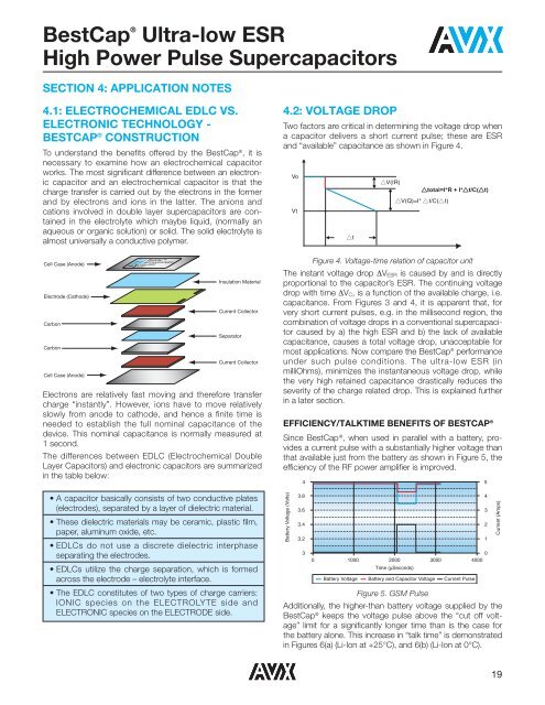
4.2: VOLTAGE DROP<br />
Two factors are critical in determining the voltage drop when<br />
a capacitor delivers a short current pulse; these are <strong>ESR</strong><br />
and “available” capacitance as shown in Figure 4.<br />
Figure 4. Voltage-time relation of capacitor unit<br />
The instant voltage drop ΔV <strong>ESR</strong> is caused by and is directly<br />
proportional to the capacitor’s <strong>ESR</strong>. The continuing voltage<br />
drop with time ΔV C , is a function of the available charge, i.e.<br />
capacitance. From Figures 3 and 4, it is apparent that, for<br />
very short current pulses, e.g. in the millisecond region, the<br />
combination of voltage drops in a conventional supercapacitor<br />
caused by a) the high <strong>ESR</strong> and b) the lack of available<br />
capacitance, causes a total voltage drop, unacceptable for<br />
most applications. Now compare the <strong>BestCap</strong> ® performance<br />
under such pulse conditions. The ultra-low <strong>ESR</strong> (in<br />
milliOhms), minimizes the instantaneous voltage drop, while<br />
the very high retained capacitance drastically reduces the<br />
severity of the charge related drop. This is explained further<br />
in a later section.<br />
EFFICIENCY/TALKTIME BENEFITS OF BESTCAP ®<br />
Since <strong>BestCap</strong> ® , when used in parallel with a battery, provides<br />
a current pulse with a substantially higher voltage than<br />
that available just from the battery as shown in Figure 5, the<br />
efficiency of the RF power amplifier is improved.<br />
Battery Voltage (Volts)<br />
Vo<br />
Vt<br />
4<br />
3.8<br />
3.6<br />
3.4<br />
3.2<br />
3<br />
▲t<br />
▲V(IR)<br />
0<br />
0 1000 2000 3000 4000<br />
Time (µSeconds)<br />
▲total=I*R + I*▲t/C(▲t)<br />
▲V(Q)=I* ▲t/C(▲t)<br />
Battery Voltage Battery and Capacitor Voltage Current Pulse<br />
Figure 5. GSM Pulse<br />
Additionally, the higher-than battery voltage supplied by the<br />
<strong>BestCap</strong> ® keeps the voltage pulse above the “cut off voltage”<br />
limit for a significantly longer time than is the case for<br />
the battery alone. This increase in “talk time” is demonstrated<br />
in Figures 6(a) (Li-Ion at +25°C), and 6(b) (Li-Ion at 0°C).<br />
5<br />
4<br />
3<br />
2<br />
1<br />
Current (Amps)<br />
19


