BestCap Ultra Low ESR Supercapacitor - AVX
BestCap Ultra Low ESR Supercapacitor - AVX
BestCap Ultra Low ESR Supercapacitor - AVX
You also want an ePaper? Increase the reach of your titles
YUMPU automatically turns print PDFs into web optimized ePapers that Google loves.
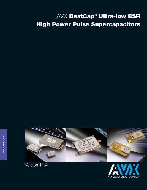
<strong>AVX</strong> <strong>BestCap</strong> ® <strong>Ultra</strong>-low <strong>ESR</strong><br />
High Power Pulse <strong>Supercapacitor</strong>s<br />
www.avx.com<br />
Version 11.4
<strong>BestCap</strong> ®<br />
<strong>Ultra</strong>-low <strong>ESR</strong><br />
High Power Pulse <strong>Supercapacitor</strong>s<br />
Table of Contents<br />
An Introduction to <strong>BestCap</strong> ® . . . . . . . . . . . . . . . . . . . . . . . . . . . . . . . . . . . . . . . . . . . . . . . . . . . . . . . . . . . . . . . . . . . . . . . . . . . . . . . . . . . . . . . . . . . . . . . . . . . . . . 2<br />
<strong>BestCap</strong> ® General Information . . . . . . . . . . . . . . . . . . . . . . . . . . . . . . . . . . . . . . . . . . . . . . . . . . . . . . . . . . . . . . . . . . . . . . . . . . . . . . . . . . . . . . . . . . . . . . . . . . . 3<br />
SECTION 1: Electrical Ratings (A-B Series) . . . . . . . . . . . . . . . . . . . . . . . . . . . . . . . . . . . . . . . . . . . . . . . . . . . . . . . . . . . . . . . . . . . . . . . . . . . . 4<br />
Electrical Ratings (BZ01/02/05/09) . . . . . . . . . . . . . . . . . . . . . . . . . . . . . . . . . . . . . . . . . . . . . . . . . . . . . . . . . . . . . . . . . . . . . . 5<br />
SECTION 2: Mechanical Specifications (A-Lead) . . . . . . . . . . . . . . . . . . . . . . . . . . . . . . . . . . . . . . . . . . . . . . . . . . . . . . . . . . . . . . . . . . . 7<br />
Mechanical Specifications (C-Lead) . . . . . . . . . . . . . . . . . . . . . . . . . . . . . . . . . . . . . . . . . . . . . . . . . . . . . . . . . . . . . . . . . . . 8<br />
Mechanical Specifications (H-Lead) . . . . . . . . . . . . . . . . . . . . . . . . . . . . . . . . . . . . . . . . . . . . . . . . . . . . . . . . . . . . . . . . . . . 9<br />
Mechanical Specifications (L-Lead) . . . . . . . . . . . . . . . . . . . . . . . . . . . . . . . . . . . . . . . . . . . . . . . . . . . . . . . . . . . . . . . . . . 10<br />
Mechanical Specifications (N-Lead) . . . . . . . . . . . . . . . . . . . . . . . . . . . . . . . . . . . . . . . . . . . . . . . . . . . . . . . . . . . . . . . . . 11<br />
Mechanical Specifications (S-Lead). . . . . . . . . . . . . . . . . . . . . . . . . . . . . . . . . . . . . . . . . . . . . . . . . . . . . . . . . . . . . . . . . . 12<br />
Packaging Specifications (BZ01/02/05/09). . . . . . . . . . . . . . . . . . . . . . . . . . . . . . . . . . . . . . . . . . . . . . . . . . . . . . . 13<br />
Packaging Quantities . . . . . . . . . . . . . . . . . . . . . . . . . . . . . . . . . . . . . . . . . . . . . . . . . . . . . . . . . . . . . . . . . . . . . . . . . . . . . . . . . . . . . . . . . 13<br />
Cleaning/Handling/Storage Conditions/Part Marking/Termination Finish . . . 14<br />
Product Safety Materials Handling/Materials and Weight. . . . . . . . . . . . . . . . . . . . . . . . . . . . . . 15<br />
Typical Weight Data. . . . . . . . . . . . . . . . . . . . . . . . . . . . . . . . . . . . . . . . . . . . . . . . . . . . . . . . . . . . . . . . . . . . . . . . . . . . . . . . . . . . . . . . . . . . 15<br />
SECTION 3: Electrical Characteristics – Schematic, Typical Characteristics . . . . . . . . . . . . . . . . . . . 16<br />
Mounting Procedure on a PCB for <strong>BestCap</strong> ® . . . . . . . . . . . . . . . . . . . . . . . . . . . . . . . . . . . . . . . . . . . . . . . . . . . 17<br />
Qualification Test Summary. . . . . . . . . . . . . . . . . . . . . . . . . . . . . . . . . . . . . . . . . . . . . . . . . . . . . . . . . . . . . . . . . . . . . . . . . . . . . . . 18<br />
SECTION 4: Application Notes . . . . . . . . . . . . . . . . . . . . . . . . . . . . . . . . . . . . . . . . . . . . . . . . . . . . . . . . . . . . . . . . . . . . . . . . . . . . . . . . . . . . . . . . . . . . . . . 19<br />
<strong>BestCap</strong> ® Construction/Voltage Drop. . . . . . . . . . . . . . . . . . . . . . . . . . . . . . . . . . . . . . . . . . . . . . . . . . . . . . . . . . . . . . . 19<br />
Enhancing the Power Capability of Primary Batteries21 <strong>BestCap</strong> ® for<br />
GSM/GPRS PCMCIA Modems . . . . . . . . . . . . . . . . . . . . . . . . . . . . . . . . . . . . . . . . . . . . . . . . . . . . . . . . . . . . . . . . . . . . . . . . . . . 22<br />
SECTION 5: Extended Temperature Range. . . . . . . . . . . . . . . . . . . . . . . . . . . . . . . . . . . . . . . . . . . . . . . . . . . . . . . . . . . . . . . . . . . . . . . . . . . 23<br />
NOTICE: Specifications are subject to change without notice. Contact your nearest <strong>AVX</strong> Sales Office for the latest specifications. All statements, information and<br />
data given herein are believed to be accurate and reliable, but are presented without guarantee, warranty, or responsibility of any kind, expressed or implied.<br />
Statements or suggestions concerning possible use of our products are made without representation or warranty that any such use is free of patent infringement<br />
and are not recommendations to infringe any patent. The user should not assume that all safety measures are indicated or that other measures may not be required.<br />
Specifications are typical and may not apply to all applications.
<strong>BestCap</strong> ®<br />
<strong>Ultra</strong>-low <strong>ESR</strong><br />
High Power Pulse <strong>Supercapacitor</strong>s<br />
INTRODUCING<br />
BESTCAP ® : A NEW GENERATION OF PULSE SUPERCAPACITORS<br />
<strong>Supercapacitor</strong>s (also referred to as Electrochemical<br />
Capacitors or Double Layer Capacitors) have rapidly become<br />
recognized, not only as an excellent compromise between<br />
“electronic” or “dielectric” capacitors such as ceramic,<br />
tantalum, film and aluminum electrolytic, and batteries (Figure<br />
1), but also as a valuable technology for providing a unique<br />
combination of characteristics, particularly very high energy,<br />
power and capacitance densities.<br />
There are, however, two limitations associated with<br />
conventional supercapacitors, namely: high <strong>ESR</strong> in the tens<br />
of Ohms range, and high capacitance loss when required to<br />
supply very short duration current pulses. <strong>BestCap</strong> ®<br />
successfully addresses both of these limitations.<br />
The capacitance loss in the millisecond region is caused by<br />
the charge transfer (i.e. establishment of capacitance) being<br />
carried out primarily by relatively slow moving ions in double<br />
layer capacitors.<br />
Figure 1. Specific Energy of Capacitor Types<br />
SPECIFIC ENERGY<br />
10000<br />
TANTALUM<br />
POLYMER<br />
ELECTROLYTIC<br />
ALUMINUM<br />
ELECTROLYTIC<br />
CAPACITOR<br />
1<br />
0.1 1<br />
10<br />
100 1000 10000<br />
Capacitance (mF)<br />
®<br />
1000<br />
100<br />
10<br />
Specific Energy (mFV/cc)<br />
In the above-mentioned “electronic” capacitors, the charge<br />
transfer is performed by fast electrons, thereby creating<br />
virtually instant rated capacitance value. In the <strong>BestCap</strong> ® , a<br />
unique proton polymer membrane is used – charge transfer<br />
by protons is close to the transfer rate for electrons and<br />
orders of magnitude greater than organic molecules. Figure<br />
2 below illustrates the severe capacitance loss experienced<br />
by several varieties of supercapacitors, under short pulse<br />
width conditions. It can also be seen from Figure 2, how well<br />
<strong>BestCap</strong> ® retains its capacitance with reducing pulse widths.<br />
For comparison purposes, the characteristic of an equivalent<br />
capacitance value aluminum electrolytic capacitor is shown<br />
in Figure 2. The electrolytic capacitor is many times the volume<br />
of the <strong>BestCap</strong> ® .<br />
Figure 2. Actual Capacitance vs. Pulse Width<br />
Actual Cap. (% of Nominal)<br />
100%<br />
80%<br />
60%<br />
40%<br />
20%<br />
0%<br />
1000 100<br />
Pulse Width (msec)<br />
10 1<br />
®<br />
EDLC-Electrochemical<br />
double layer capacitor<br />
Aluminum Electrolytic Capacitor<br />
manufacturer A EDLC<br />
manufacturer B EDLC<br />
manufacturer C EDLC<br />
2
<strong>BestCap</strong> ®<br />
<strong>Ultra</strong>-low <strong>ESR</strong><br />
High Power Pulse <strong>Supercapacitor</strong>s<br />
BESTCAP ® – A SERIES – MAXIMUM CAPACITANCE, LOW <strong>ESR</strong><br />
B SERIES – LOW PROFILE, LOW <strong>ESR</strong><br />
The <strong>BestCap</strong> ® is a low profile device available in four case sizes. Capacitance range is from 6.8 to 1000mF and includes 7<br />
voltage ratings from 3.6v to 16v.<br />
BESTCAP ® – AVAILABLE LEAD CONFIGURATIONS<br />
STANDARD:<br />
N-Style: Two Terminal Planar Mount<br />
(Available in BZ01, BZ05, BZ09 case only)<br />
S-Style: Three Terminal Planar Mount<br />
(Available in BZ01, BZ05, BZ09 case only)<br />
L-Style: Four Terminal Planar Mount<br />
(Available in BZ01 and BZ02 case only)<br />
A Style: Through-Hole Mount<br />
(Available in BZ01, BZ02 case only)<br />
H-Style: Extended Stand-Off Through Hole Mount<br />
(Available in BZ01, BZ02 case only)<br />
C-Style: Connector Mount<br />
(Available in BZ01, BZ05 case only)<br />
BODY DIMENSIONS<br />
Case Size L ±0.5 (0.020) W ±0.2 (0.008) H nom<br />
mm (inches) mm (inches) mm (inches)<br />
BZ01 28 (1.102) 17 (0.669) 2.3 (0.091) – 6.5 (0.256)<br />
BZ02 48 (1.890) 30 (1.181) 2.9 (0.114) – 6.8 (0.268)<br />
BZ05 20 (0.787) 15 (0.590) 2.3 (0.091) – 6.5 (0.256)<br />
BZ09 17 (0.669) 15 (0.590) 2.3 (0.091)<br />
LEAD-FREE COMPATIBLE<br />
COMPONENT<br />
ELECTRICAL SPECIFICATIONS Full dimensional specifications shown in section (2)<br />
Capacitance range:<br />
6.8mF – 1000mF<br />
Capacitance tolerance: –20% / +80%<br />
Voltage ratings (max): 3.6V 4.5V 5.5V 9V 12V 15V 16V<br />
Test voltages: 3.5V 4.2V 5.0V 8.4V 10.0V 11.0V 13.0V<br />
Surge test voltage: 4.5V 5.6V 6.9V 11.3V 15.0V 18.8V 20.0V<br />
Temperature range:<br />
–20°C to 70°C, consult factory for -40ºC and +75ºC options<br />
HOW TO ORDER<br />
(See Detailed Electrical Specifications for valid combinations)<br />
BZ 0 1 5 A 503 Z A B XX<br />
<strong>BestCap</strong> ® Standard Case Size Rated Series Capacitance Capacitance Lead Packaging Not Used For<br />
0 = Standard 1 = 28mmx17mm Voltage A = Maximum Code Tolerance Format B = Bulk Standard<br />
1 = High Cap 2 = 48mmx30mm 3 = 3.6V Capacitance (Farad Code) Z = (-20/+80)% A, C, H, L Product<br />
5 = 20mmx15mm 4 = 4.5V B = <strong>Low</strong> Profile N or S (Consult<br />
9 = 17mmx15mm 5 = 5.5V Factory For<br />
9 = 9.0V Special<br />
C = 12.0V<br />
Requirements)<br />
F = 15.0V<br />
G = 16.0V<br />
3
<strong>BestCap</strong> ®<br />
<strong>Ultra</strong>-low <strong>ESR</strong><br />
High Power Pulse <strong>Supercapacitor</strong>s<br />
SECTION 1: ELECTRICAL RATINGS<br />
CAPACITANCE / VOLTAGE / CASE SIZE MATRIX<br />
A-SERIES – MAXIMUM CAPACITANCE<br />
Capacitance Rated Voltage DC at 25°C<br />
mF Code 3.6V 5.5V 9.0V 12.0V 16.0V<br />
Case Lead Case Lead Case Lead Case Lead Case Lead<br />
Size Styles Size Styles Size Styles Size Styles Size Styles<br />
10 103 BZ05 C, N, S<br />
22 223 BZ01 A, C, H, S<br />
33 333 BZ05 C, N, S BZ01 A, C, H, S<br />
47 473 BZ11 S<br />
50 503 BZ01 A, C, H, S, L<br />
68 683 BZ05 S<br />
70 703 BZ01 A, C, H, S, L<br />
90 903 BZ02 A, H, L<br />
100 104 BZ01 A, H, S, L<br />
120 124 BZ02 A, H, L BZ12 A, L, N<br />
140 144 BZ01 A, H, S, L<br />
150 154 BZ15 S<br />
200 204 BZ02 A, H, L<br />
280 284 BZ02 A, H, L<br />
400 404 BZ02 A, H, L<br />
470 474 BZ12 A<br />
560 564 BZ02 A, H, L<br />
1000 105 BZ12 A, H, L<br />
B-SERIES – LOW PROFILE<br />
Capacitance Rated Voltage DC at 25°C<br />
mF Code 3.6V 4.5V 5.5V 9.0V 12.0V 15.0V<br />
Case Lead Case Lead Case Lead Case Lead Case Lead Case Lead<br />
Size Styles Size Styles Size Styles Size Styles Size Styles Size Styles<br />
6.8 682 BZ05 C, N, S<br />
15 153 BZ09 N, S BZ05 C, N, S BZ01 A, H, S<br />
22 223 BZ05 N, S BZ01 A, H, S<br />
30 303 BZ01 C, S, N<br />
33 333 BZ01 C, S, N BZ05 S, N<br />
47 473 BZ15 N, S BZ11 S<br />
50 503 BZ01 C, S, N<br />
60 603 BZ01 A, H, S, L<br />
100 104 BZ11 C, S, N<br />
4
<strong>BestCap</strong> ®<br />
<strong>Ultra</strong>-low <strong>ESR</strong><br />
High Power Pulse <strong>Supercapacitor</strong>s<br />
SECTION 1: ELECTRICAL RATINGS<br />
ELECTRICAL RATINGS - SEE SECTION 2 FOR DIMENSIONAL REFERENCES<br />
BZ 01 CASE SIZE<br />
Part<br />
Number<br />
Rated<br />
Capacitance<br />
<strong>ESR</strong><br />
Leakage<br />
Height A-Lead Height C-Lead Height H-Lead Height S-Lead<br />
Height S-Lead<br />
Voltage<br />
(mF)<br />
(mOhms at 1 kHz)<br />
Current<br />
(mm) (mm) (mm)<br />
(AJ)*<br />
(Volts) (µA max) (mm) (mm)<br />
Nominal<br />
+80%, –20% Typical Maximum Maximum H max H max H max H max H max<br />
3.6V<br />
BZ013B503Z_B 50 100 120 5 NA 2.1 NA 3.2 2.1<br />
BZ013A703Z_B<br />
70 140 168 5 3.5 2.9 6.4 4.0 2.9<br />
3.6V<br />
BZ113B104Z_B 100 100 120 10 NA 2.1 NA 3.2 2.1<br />
BZ013A144Z_B 140 70 84 5 5.3 NA 8.2 5.8 NA<br />
4.5V<br />
BZ014B333Z_B 4.5V 33 150 180 5 NA 2.4 NA 3.5 2.4<br />
5.5V<br />
BZ015B303Z_B 30 160 192 5 NA 2.7 NA 3.8 2.7<br />
BZ015A503Z_B<br />
50 160 192 5 4.1 3.5 7.0 4.6 3.5<br />
5.5V<br />
BZ015B603Z_B 60 80 96 10 5.4 NA 8.3 5.9 NA<br />
BZ015A104Z_B 100 80 96 10 6.7 NA 9.6 7.2 NA<br />
9.0V<br />
BZ019B223Z_B<br />
22 250 300 5 4.7 NA 7.6 5.2 4.1<br />
9.0V<br />
BZ019A333Z_B 33 250 300 5 5.5 4.9 8.4 6.0 4.9<br />
12.0V<br />
BZ01CB153Z_B 12.0V<br />
15 350 420 5 5.9 NA 8.8 6.4 5.3<br />
BZ01CA223Z_B 22 350 420 5 7.1 6.5 10.0 7.6 6.5<br />
* Select S-Lead BZ01 <strong>BestCap</strong> ® are available with insulation on the bottom of the part and zero clearance from the PCB. See section 2.6 for<br />
dimensions. To order, please add special requirement AJ to the end of the part number. Example: BZ013B503ZSBAJ<br />
BZ 02 CASE SIZE<br />
Part<br />
Number<br />
Rated<br />
Voltage<br />
(Volts)<br />
Capacitance<br />
(mF)<br />
<strong>ESR</strong><br />
(mOhms at 1 kHz)<br />
Leakage<br />
Current<br />
(µA max)<br />
Height A-Lead Height H-Lead Height L-Lead<br />
(mm) (mm) (mm)<br />
Nominal<br />
+80%, –20% Typical Maximum Maximum H max H max H max<br />
3.6V<br />
BZ023A284Z_B<br />
280 45 54 20 3.5 6.4 3.7<br />
3.6V<br />
BZ023A564Z_B 560 25 30 40 5.3 8.2 5.5<br />
5.5V<br />
BZ025A204Z_B 200 60 72 20 4.1 7.0 4.3<br />
BZ025A404Z_B 5.5V 400 35 42 40 6.7 9.6 6.9<br />
BZ125A105Z_B 1000 35 42 120 6.7 9.6 6.9<br />
9.0 V<br />
BZ029A124Z_B 9.0V 120 70 84 20 5.8 8.7 6.0<br />
12.0V<br />
BZ02CA903Z_B 12.0V 90 90 108 20 7.4 10.3 7.6<br />
16.0V<br />
BZ12GA124Z_B 16.0V 120 160 192 60 9.1 9.1<br />
All capacitance, <strong>ESR</strong>, and leakage current values listed in these tables are at room temperature only.<br />
5
<strong>BestCap</strong> ®<br />
<strong>Ultra</strong>-low <strong>ESR</strong><br />
High Power Pulse <strong>Supercapacitor</strong>s<br />
BZ 05 CASE SIZE<br />
Part<br />
Number<br />
Rated<br />
Voltage<br />
(Volts)<br />
Capacitance<br />
(mF)<br />
<strong>ESR</strong><br />
(mOhms at 1 kHz)<br />
Leakage<br />
Current<br />
(µA max)<br />
Height C-Lead Height N-Lead Height S-Lead<br />
(mm) (mm) (mm)<br />
Nominal<br />
+80%, –20% Typical Maximum Maximum H max H max H max<br />
4.5V<br />
BZ054B223Z_B<br />
22 170 204 5 NA 2.3 2.3<br />
4.5V<br />
BZ154B473Z_B 47 170 204 10 NA 2.3 2.3<br />
5.5V<br />
BZ055B153Z_B 15 250 300 5 2.7 2.7 2.7<br />
BZ055A333Z_B 5.5V 33 250 300 5 3.5 3.5 3.5<br />
BZ055B333Z_B 33 125 150 10 NA NA 4.8<br />
BZ155A104Z_B 100 125 150 20 NA NA 6.1<br />
12.0V<br />
BZ05CA103Z_B 12.0V 10 500 600 5 6.5 6.5 6.5<br />
15.0V<br />
BZ05FB682Z_B 15.0V 6.8 500 600 10 4.8 5.8 5.8<br />
BZ 09 CASE SIZE<br />
Part<br />
Number<br />
Rated<br />
Voltage<br />
(Volts)<br />
Capacitance<br />
(mF)<br />
<strong>ESR</strong><br />
(mOhms at 1 kHz)<br />
Leakage<br />
Current<br />
(µA max)<br />
* The 4.5V BZ09 <strong>BestCap</strong>® are available only in a special low profile version.<br />
Height N-Lead Height S-Lead<br />
(mm) (mm)<br />
Nominal<br />
+80%, –20% Typical Maximum Maximum H max H max<br />
4.5V<br />
BZ094B153Z_BAI 4.5V 15 250 300 5 2.4* 2.3*<br />
All capacitance, <strong>ESR</strong>, and leakage current values listed in these tables are at room temperature only.<br />
6
<strong>BestCap</strong> ®<br />
<strong>Ultra</strong>-low <strong>ESR</strong><br />
High Power Pulse <strong>Supercapacitor</strong>s<br />
SECTION 2: MECHANICAL SPECIFICATIONS<br />
2.1 Case Dimensions & Recommended PCB Layout<br />
2.1.1: A-Style Configuration (Pin Through Hole)<br />
L<br />
BL<br />
W<br />
H<br />
LO<br />
S<br />
LW<br />
LL<br />
TABLE 2.1.1: A-STYLE DIMENSIONS<br />
Case Dimensions: mm (inches)<br />
Case Size BL W H L S LO LW LL<br />
+1.0 (0.040)/-0 +1.0 (0.040)/-0 (Maximum) ±1.0 (0.040) ±0.1 (0.004) ±0.2 (0.008) ±0.2 (0.008) ±0.2 (0.008)<br />
BZ01 28 (1.102) 17 (0.669) See Section 1 32 0.45 (0.018) 1.5 (0.059) 1.27 (0.050) 2.5 (0.098)<br />
BZ02 48 (1.890) 30 (1.181) See Section 1 52 0.45 (0.018) 1.5 (0.059) 1.27 (0.050) 2.5 (0.098)<br />
2.1.2: A-Lead Configuration (Through Hole)<br />
C<br />
D<br />
A<br />
B<br />
TABLE 2.1.2: A-LEAD LAYOUT DIMENSIONS<br />
Recommended PCB Dimensions: mm (inches)<br />
Case Size A B C D<br />
±0.05 (0.002) ±0.05 (0.002) ±0.05 (0.002) ±0.1 (0.004)<br />
BZ01 17.25 (0.679) 8.90 (0.350) 28 (1.102) Ø1.4 (0.055)<br />
BZ02 30.25 (1.191) 8.90 (0.350) 48 (1.890) Ø1.4 (0.055)<br />
7
<strong>BestCap</strong> ®<br />
<strong>Ultra</strong>-low <strong>ESR</strong><br />
High Power Pulse <strong>Supercapacitor</strong>s<br />
SECTION 2: MECHANICAL SPECIFICATIONS (cont’d)<br />
2.2.1: C-Style Case Dimensions<br />
L<br />
BL<br />
W<br />
B<br />
LW<br />
H<br />
TABLE 2.2.1: C-STYLE CASE DIMENSIONS<br />
Case Dimensions: mm (inches)<br />
L W H BL LW B<br />
Case Size ±0.5 (0.020) +1.0 (0.040)/-0 (Maximum) +1.0 (0.040)/-0 ±0.2 (0.008) ±0.5 (0.020)<br />
BZ01 31 (1.220) 17 (0.669) See Section 1 28 (1.102) 2.5 (0.098) 10 (0.394)<br />
BZ05 23 (0.906) 15 (0.591) See Section 1 20 (0.787) 2.5 (0.098) 10 (0.394)<br />
2.2.2: C-Lead Configuration<br />
CW<br />
KYOCERA ELCO<br />
046284024001868+<br />
24 PIN CONNECTOR<br />
W<br />
Pinouts:<br />
1-5 Common*<br />
6-18 Not Connected<br />
19-24 Positive*<br />
* Devices are non polar but it is usual<br />
to maintain case at ground potential.<br />
CL<br />
G<br />
OAL<br />
Connector must be ordered separately.<br />
TABLE 2.2.2: C-LEAD LAYOUT DIMENSIONS<br />
PCB Dimensions: mm (inches)<br />
Case Size OAL W CW* CL* G<br />
±0.5 (0.020) +1.0 (0.040)/-0 ±0.5 (0.020)<br />
BZ01 33.05 (1.301) 17 (0.669) 4.05 (0.159) 13.9 (0.547) 1.0 (0.039)<br />
BZ05 25.05 (0.986) 15 (0.591) 4.05 (0.159) 13.9 (0.547) 1.0 (0.039)<br />
* See Connector data sheet.<br />
8
<strong>BestCap</strong> ®<br />
<strong>Ultra</strong>-low <strong>ESR</strong><br />
High Power Pulse <strong>Supercapacitor</strong>s<br />
SECTION 2: MECHANICAL SPECIFICATIONS (cont’d)<br />
2.3.1: H-Style Case Dimensions (Through Hole Extended Height)<br />
L<br />
BL<br />
W<br />
H<br />
LO<br />
LL<br />
S<br />
LW<br />
TABLE 2.3.1: H-STYLE CASE DIMENSIONS<br />
Case Dimensions: mm (inches)<br />
Case Size<br />
S<br />
BL W H L<br />
+0.5 (0.020)/<br />
LO LW LL<br />
+1.0 (0.040)/-0 +1.0 (0.040)/-0 (Maximum) ±1.0 (0.040)<br />
-0.4 (0.016)<br />
±0.2 (0.008) ±0.2 (0.008) ±0.2 (0.008)<br />
BZ01 28 (1.102) 17 (0.669) See Section 1 32 3.0 1.5 (0.059) 1.27 (0.050) 2.5 (0.098)<br />
BZ02 48 (1.890) 30 (1.181) See Section 1 52 3.0 1.5 (0.059) 1.27 (0.050) 2.5 (0.098)<br />
2.3.2: H-Lead Configuration (Through Hole Extended Height)<br />
C<br />
D<br />
A<br />
B<br />
TABLE 2.3.2: H-LEAD LAYOUT DIMENSIONS<br />
PCB Dimensions: mm (inches)<br />
Case Size A B C D<br />
±0.05 (0.002) ±0.05 (0.002) ±0.05 (0.002) ±0.1 (0.004)<br />
BZ01 17.25 (0.679) 8.90 (0.350) 28 (1.102) Ø1.4 (0.055)<br />
BZ02 30.25 (1.191) 8.90 (0.350) 48 (1.890) Ø1.4 (0.055)<br />
9
<strong>BestCap</strong> ®<br />
<strong>Ultra</strong>-low <strong>ESR</strong><br />
High Power Pulse <strong>Supercapacitor</strong>s<br />
SECTION 2: MECHANICAL SPECIFICATIONS (cont’d)<br />
2.4.1: L-Lead Configuration (Planar Mount)<br />
L<br />
BL<br />
W<br />
LO<br />
LL<br />
LW<br />
S<br />
H<br />
TABLE 2.4.1: L-STYLE CASE DIMENSIONS<br />
Case Dimensions: mm (inches)<br />
Case Size BL W H L S LO LW LL<br />
+1.0 (0.040)/-0 +1.0 (0.040)/-0 (Maximum) ±1.0 (0.040) ±0.2 (0.008) ±0.2 (0.008) ±0.2 (0.008) ±0.5 (0.020)<br />
BZ01 28 (1.102) 17 (0.6691) See Section 1 33 0.55 (0.022) 1.5 (0.059) 1.27 (0.050) 2.4 (0.098)<br />
BZ02 48 (1.890) 30 (1.181) See Section 1 52 0.55 (0.022) 1.5 (0.059) 1.27 (0.050) 2.4 (0.098)<br />
2.4.2: L-Lead Configuration (Planar Mount)<br />
C<br />
A<br />
B<br />
PW<br />
PL<br />
TABLE 2.4.2: L-STYLE LEAD LAYOUT<br />
PCB Dimensions: mm (inches)<br />
Case Size A B C PL PW<br />
±0.1 (0.004) ±0.1 (0.004) ±0.1 (0.004) ±0.2 (0.008) ±0.2 (0.008)<br />
BZ01 19.2 (0.776) 10.8 (0.425) 28 (1.102) 3.0 (0.118) 3.7 (0.146)<br />
10
<strong>BestCap</strong> ®<br />
<strong>Ultra</strong>-low <strong>ESR</strong><br />
High Power Pulse <strong>Supercapacitor</strong>s<br />
SECTION 2: MECHANICAL SPECIFICATIONS (cont’d)<br />
2.5.1: N-Lead Configuration<br />
BL<br />
L<br />
LL<br />
LW<br />
W<br />
LC<br />
B<br />
EW<br />
H<br />
EL<br />
TABLE 2.5.1: N-STYLE CASE DIMENSIONS<br />
Case Dimensions: mm (inches)<br />
Case Size L W H B LL LW EL EW<br />
±0.5 (0.020) +1.0 (0.040)/-0 (Maximum) ±0.5 (0.020) ±0.2 (0.008) ±0.2 (0.008) ±0.5 (0.020) ±0.5 (0.020)<br />
BZ01 30.5 (1.201) 17 (0.669) See Section 1 11.2 (0.441) 2.5 (0.098) 1.4 (0.055) 2.5 (0.098) 1.4 (0.055)<br />
BZ05 23.5 (0.925) 15 (0.591) See Section 1 7.5 (0.295) 2.5 (0.098) 2.5 (0.098) 3.5 (0.138) 2.5 (0.098)<br />
BZ09 20.5 (0.807) 15 ( 0.591) See Section 1 7.5 (0.295) 2.5 (0.098) 2.5 (0.098) 3.5 (0.138) 2.5 (0.098)<br />
2.5.2: N-Lead Configuration (Planar Mount)<br />
A<br />
PW<br />
LPL<br />
B<br />
TABLE 2.5.2: N-STYLE LEAD LAYOUT<br />
PCB Dimensions: mm (inches)<br />
Case Size A B PW LPL RPL<br />
±0.5 (0.020) ±0.1 (0.004) ±0.1 (0.004) ±0.1 (0.004) ±0.1 (0.004)<br />
BZ01 0.5 (0.020) 9.5 (0.374) 3.2 (0.126) 3.5 (0.138) 3.5 (0.138)<br />
BZ05 1.0 (0.039) 5.9 (0.232) 4.1 (0.161) 2.5 (0.098) 3.5 (0.138)<br />
BZ09 1.0 (0.039) 5.9 (0.232) 4.1 (0.161) 2.5 (0.098) 3.5 (0.138)<br />
RPL<br />
11
<strong>BestCap</strong> ®<br />
<strong>Ultra</strong>-low <strong>ESR</strong><br />
High Power Pulse <strong>Supercapacitor</strong>s<br />
SECTION 2: MECHANICAL SPECIFICATIONS (cont’d)<br />
2.6.1: S-Lead Configuration (Planar Mount)<br />
L<br />
BL<br />
W<br />
EW<br />
LW<br />
LL<br />
EL<br />
S<br />
H<br />
TABLE 2.6.1: S-STYLE CASE DIMENSIONS<br />
Case Dimensions: mm (inches)<br />
Case Size BL W H L EL EW LL LW<br />
+1.0 (0.040)/-0 +1.0 (0.040)/-0 (Maximum) ±1.0 (0.040) ±0.5 (0.020) ±0.2 (0.008) ±0.5 (0.020) ±0.2 (0.008)<br />
BZ01 28 (1.102) 17 (0.669) See Section 1 38.7 (1.524) 5.0 (0.197) 4.5 (0.177) 5.7 (0.224) 2.0 (0.079)<br />
BZ05 20 (0.787) 15 (0.591) See Section 1 26 (1.024) 3.5 (0.138) 2.5 (0.098) 2.5 (0.098) 2.5 (0.098)<br />
BZ09 17 (0.669) 15 (0.591) See Section 1 23 (0.906) 3.5 (0.138) 2.5 (0.098) 2.5 (0.098) 2.5 (0.098)<br />
2.6.2: S-Lead Layout (Planar Mount)<br />
B<br />
Planar Mount<br />
“S”<br />
Available in<br />
BZ01, BZ05<br />
& BZ09<br />
Case Size Only<br />
A<br />
EPW<br />
LPW<br />
EPL<br />
LPL<br />
TABLE 2.6.2: S-STYLE PAD LAYOUT DIMENSIONS<br />
PCB Dimensions: mm (inches)<br />
Case Size A B EPL EPW LPL LPW<br />
±0.1 (0.004) ±0.1 (0.004) ±0.1 (0.004) ±0.1 (0.004) ±0.1 (0.004) ±0.1 (0.004)<br />
BZ01 13.0 (0.512) 35.1 (1.382) 4.5 (0.177) 6.0 (0.236) 5.8 (0.228) 3.5 (0.138)<br />
BZ05 10.0 (0.394) 25.0 (0.984) 3.0 (0.118) 4.5 (0.177) 2.9 (0.114) 4.5 (0.177)<br />
BZ09 10.0 (0.394) 22.0 (0.886) 3.0 (0.118) 4.5 (0.177) 2.9 (0.114) 4.5 (0.177)<br />
12
<strong>BestCap</strong> ®<br />
<strong>Ultra</strong>-low <strong>ESR</strong><br />
High Power Pulse <strong>Supercapacitor</strong>s<br />
SECTION 2: MECHANICAL SPECIFICATIONS (cont’d)<br />
2.7: Packaging Specifications<br />
BZ01 Case:<br />
50.8<br />
(2.00)<br />
167.6<br />
(6.60)<br />
13.2<br />
(0.52)<br />
31.8<br />
(1.25)<br />
167.6<br />
(6.60)<br />
BZ02 Case:<br />
167.6<br />
(6.60)<br />
71.0<br />
(2.80)<br />
13.2<br />
(0.52)<br />
38.1<br />
(1.50)<br />
167.6<br />
(6.60)<br />
BZ05, BZ09 Case: 167.6<br />
38.1<br />
(1.50)<br />
(6.60)<br />
13.2<br />
(0.52)<br />
28.6<br />
(1.12)<br />
167.6<br />
(6.60)<br />
This specification applies when our electrochemical supercapacitors are packed using a 165mm by 165mm container. The<br />
parts are held in place by a 166mm by 166mm lid.<br />
PACKAGING QUANTITIES:<br />
Size No. of Rows No. of Columns Pieces/Tray<br />
BZ01 5 3 15<br />
BZ02 4 2 8<br />
BZ05 5 4 20<br />
BZ09 5 4 20<br />
13
<strong>BestCap</strong> ®<br />
<strong>Ultra</strong>-low <strong>ESR</strong><br />
High Power Pulse <strong>Supercapacitor</strong>s<br />
SECTION 2: MECHANICAL SPECIFICATIONS<br />
2.8 CLEANING<br />
The <strong>BestCap</strong> ® supercapacitor is cleaned prior to shipment.<br />
Should cleaning be required prior to insertion into the application,<br />
it is recommended to use a small amount of propanol<br />
taking care not to remove the label. The cell should not be<br />
immersed due to possible deterioration of the epoxy encapsulation.<br />
Care must also be taken not to bend the leads.<br />
2.9 HANDLING<br />
Care should be taken not to allow grease or oil into the part<br />
as it may lead to soldering problems. Handling should be<br />
minimized to reduce possible bending of the electrodes<br />
leads.<br />
2.10 STORAGE CONDITIONS<br />
<strong>AVX</strong> <strong>BestCap</strong> ® supercapacitor are unaffected by the following<br />
storage conditions.<br />
Temperature: 15°C ~ 35°C<br />
Humidity: 45% RH ~ 75% RH<br />
This temperature and humidity range is specified for consideration<br />
of terminal solderability. <strong>BestCap</strong> ® are able to withstand<br />
shelf life at 70ºC for 1000 hours.<br />
2.11 PART MARKING<br />
Voltage<br />
Capacitance<br />
Date and<br />
Lot Code<br />
2.12 TERMINATION FINISH<br />
Gold over nickel, tin over nickel.<br />
Country of Origin<br />
14
<strong>BestCap</strong> ®<br />
<strong>Ultra</strong>-low <strong>ESR</strong><br />
High Power Pulse <strong>Supercapacitor</strong>s<br />
2.13 PRODUCT SAFETY MATERIALS HANDLING<br />
Precautions<br />
• Do not disassemble the capacitor.<br />
• Do not incinerate the capacitor and do not use incineration<br />
for disposal.<br />
• The capacitor contains polymeric electrolyte and carbon<br />
electrodes. However, since the polymer is composed of<br />
acid based chemical ingredients, if punctured or<br />
dismantled and the skin is contacted with the capacitor<br />
internal components, it is recommended to wash the skin<br />
with excess of running water.<br />
• If any internal material contacts the eyes, rinse thoroughly<br />
with running water.<br />
• Be aware not to apply over-voltage. Combination of<br />
charging at voltage greater than the nominal, plus high<br />
temperature, plus prolonged time may result in capacitor<br />
bulging or rupturing.<br />
2.14 BESTCAP ® MATERIALS AND WEIGHT<br />
Materials<br />
Constituent<br />
RoHS BZ01 BZ02 BZ05 BZ09<br />
Compliant? Weight % Weight % Weight % Weight %<br />
Case Stainless Steel YES 56.7% 44.5% 64.8% 64.8%<br />
Leads (A, H, and L lead only) Stainless Steel YES 4.2% 0.7%<br />
Electrode Stainless Steel YES 13.6% 8.0% 13.6% 13.6%<br />
Electrode Insulation Laminating Adhesive YES 2.3% 1.0% 2.4% 2.4%<br />
Core Metallized Current Collector YES 5.2% 8.0% 1.6% 1.6%<br />
Current Collector YES 2.5% 14.3% 1.0% 1.0%<br />
Active Electrode YES 1.0% 5.7% 0.4% 0.4%<br />
Core Sealant YES 0.9% 5.2% 0.3% 0.3%<br />
Encapsulant Epoxy YES 10.3% 11.4% 11.8% 11.8%<br />
Bottom Insulation Laminating Adhesive YES 2.3% 1.0% 2.4% 2.4%<br />
Label Label YES 1.0% 0.2% 1.8% 1.8%<br />
TOTAL 100% 100% 100% 100%<br />
<strong>BestCap</strong> ® is RoHS compliant<br />
May be assembled with Pb-Free solder.<br />
BESTCAP ® – TYPICAL WEIGHT DATA<br />
Rated Voltage (V) Capacitance (mF) Part Number Weight (g)<br />
3.6V 50 BZ013B503Z_B 2.9<br />
70 BZ013A703Z_B 4.2<br />
100 BZ113B104Z_B 2.9<br />
140 BZ013A144Z_B 5.3<br />
280 BZ023A284Z_B 12.2<br />
560 BZ023A564Z_B 15.9<br />
4.5V 15 BZ094B153Z_B 1.5<br />
22 BZ054B223Z_BBQ 1.8<br />
33 BZ014B333Z_B 3.2<br />
47 BZ154B473Z_BBQ 1.8<br />
5.5V 15 BZ055B153Z_B 1.9<br />
30 BZ015B303Z_B 3.4<br />
33 BZ055A333Z_B 2.3<br />
33 BZ055B333Z_B 2.1<br />
50 BZ015A503Z_B 4.6<br />
60 BZ015B603Z_B 5.5<br />
68 BZ055A683Z_B 3.4<br />
100 BZ015A104Z_B 6.1<br />
200 BZ025A204Z_B 13.3<br />
400 BZ025A404Z_B 18.4<br />
1000 BZ125A105Z_B 18.4<br />
9.0V 22 BZ019B223Z_B 4.4<br />
33 BZ019A333Z_B 5.0<br />
120 BZ029A124Z_B 15.6<br />
12.0V 10 BZ05CA103Z_B 3.5<br />
15 BZ01CB153Z_B 5.0<br />
22 BZ01CA223Z_B 6.2<br />
90 BZ02CA903Z_B 19.3<br />
15.0V 6.8 BZ05FB682Z_B 2.8<br />
16.0V 124 BZ12GA124Z_B 25<br />
15
<strong>BestCap</strong> ®<br />
<strong>Ultra</strong>-low <strong>ESR</strong><br />
High Power Pulse <strong>Supercapacitor</strong>s<br />
SECTION 3: ELECTRICAL CHARACTERISTICS – SCHEMATIC<br />
3.1 Terminal<br />
Connections:<br />
3.1.1: S-Lead<br />
3.1.2: A-, H- & L-Lead 3.1.3: C- & N-Lead<br />
Common terminals connected to case Common terminals connected to case<br />
Devices are non polar but it is usual to maintain case at ground potential<br />
SECTION 3.2: TYPICAL CHARACTERISTICS<br />
Capacitance (Farads)<br />
0.07<br />
0.06<br />
0.05<br />
0.04<br />
0.03<br />
0.02<br />
0.01<br />
Capacitance vs. Temperature<br />
<strong>ESR</strong> vs. Temperature<br />
<strong>ESR</strong> (Ohms)<br />
0.700<br />
0.600<br />
0.500<br />
0.400<br />
0.300<br />
0.200<br />
0.100<br />
0<br />
-25 -20 -15 -10 -5 0 5 10 15 20 25 30 35 40 45 50 55 60 65<br />
BZ015A503ZLB35<br />
Temperature (°C)<br />
0.000<br />
-25 -20 -15 -10 -5 0 5 10 15 20 25 30 35 40 45 50 55 60 65<br />
BZ015A503ZLB35<br />
Temperature (°C)<br />
<strong>ESR</strong> (Ohms)<br />
10<br />
1<br />
0.1<br />
<strong>ESR</strong> vs. Frequency<br />
BZ015A503<br />
BZ014A104<br />
BZ025A204<br />
<strong>ESR</strong> (Ohms)<br />
1.00E+01<br />
1.00E+00<br />
1.00E-01<br />
<strong>ESR</strong> Comparison<br />
BZ015A503<br />
BZ014A104<br />
BZ025A204<br />
0.01<br />
10 100 1,000 10,000 100,000 1,000,000 10,000,000 100,000,000<br />
Frequency (Hz)<br />
1.00E-02<br />
10 100 1,000 10,000 100,000 1,000,000 10,000,000 100,000,000<br />
Frequency (Hz)<br />
Impedance (Ohms)<br />
10<br />
1<br />
0.1<br />
Impedance vs. Frequency<br />
BZ015A503<br />
BZ014A104<br />
BZ025A204<br />
Impedance (Ohms)<br />
10<br />
1<br />
0.1<br />
Impedance Comparison<br />
BZ015A503<br />
BZ014A104<br />
BZ025A204<br />
0.01<br />
10 100 1,000 10,000 100,000 1,000,000 10,000,000 100,000,000<br />
Frequency (Hz)<br />
0.01<br />
10 100 1,000 10,000 100,000 1,000,000 10,000,000 100,000,000<br />
Frequency (Hz)<br />
16
<strong>BestCap</strong> ®<br />
<strong>Ultra</strong>-low <strong>ESR</strong><br />
High Power Pulse <strong>Supercapacitor</strong>s<br />
SECTION 3.3: MOUNTING PROCEDURE ON A PCB FOR BESTCAP ®<br />
<strong>BestCap</strong> ® products can be mounted on PCBs by either<br />
selectively heating only the capacitor terminals by using a<br />
pulsed reflow soldering station or by using hand soldering.<br />
IR Reflow or wave soldering may not be used. The main<br />
body of the device should be less than 60ºC at all times.<br />
PULSED REFLOW SOLDERING<br />
Application data for the ‘Unitek’ pulsed-reflow soldering<br />
station.<br />
Equipment:<br />
Controller<br />
Uniflow ‘Pulsed Thermode Control’<br />
Head<br />
Thin-line Reflow Solder Head<br />
Solder paste type No Clean Flux<br />
Solder composition 63% Sn, 37% Pb<br />
Percent solids 88%<br />
Solder thickness 6 mils<br />
Solder-weld tip size 0.075"<br />
Solder-weld tip force 6 lbs.<br />
Temperature profile:<br />
HAND SOLDERING STATION<br />
Equipment:<br />
Solder type:<br />
Temperature:<br />
Time:<br />
Solder Type:<br />
Temperature:<br />
Time:<br />
Temperature controlled, 50W general<br />
purpose iron<br />
63Sn/37Pb, rosin core wire<br />
400ºC (+20ºC - 100ºC)<br />
2 to 5 seconds maximum, smaller time<br />
(2 sec.) at 420ºC and 5 sec. at 300ºC,<br />
overall it being a time-temperature relationship.<br />
Shorter time, higher temperature<br />
is preferred.<br />
Lead Free, 95Sn/5Ag<br />
430ºC (+20ºC - 100ºC)<br />
2 to 5 seconds maximum, smaller time<br />
(2 sec.) at 450ºC and 5 sec. at 330ºC,<br />
overall it being a time-temperature relationship.<br />
Shorter time, higher temperature<br />
is preferred.<br />
Temperature<br />
Time<br />
Pre-heat 130ºC 0 sec.<br />
Rise 440ºC (±10) 2 sec.<br />
Reflow 440ºC (±10) 2 sec.<br />
Cool 165ºC<br />
In both cases, the main body of the <strong>BestCap</strong> ® part should be less than 60ºC at all times.<br />
17
<strong>BestCap</strong> ®<br />
<strong>Ultra</strong>-low <strong>ESR</strong><br />
High Power Pulse <strong>Supercapacitor</strong>s<br />
SECTION 3.4: QUALIFICATION TEST SUMMARY<br />
Test Test Method Parameter Limits<br />
Initial Capacitance Charge to test voltage at room temperature. Disconnect parts from Capacitance (Cap) +80% / -20%<br />
Measurement voltage to remove charging effects. Discharge cells with a constant current of rated Cap<br />
(4 mA) noting voltage and time 1 and 2 seconds after beginning discharge.<br />
C = I * dt/dv<br />
Initial DCL Charge to test voltage at room temperature. Disconnect parts from Leakage Current (DCL) Within Limit<br />
Measurement<br />
voltage to remove charging effects. Note voltage and time 5 minutes<br />
and 25 minutes after disconnecting. I = C * dV/dt<br />
Initial <strong>ESR</strong> Measurement frequency @ 1kHz; Measurement voltage @ 10 mV Equivalent Series +20% / -50%<br />
Measurement at room temperature Resistance (<strong>ESR</strong>) of typical value<br />
Load Life Apply test voltage at 70ºC for 1000 hours. Allow to cool to room DCL < 2.0x rated max.<br />
temperature and measure Cap, DCL and <strong>ESR</strong> Cap > 0.7x rated<br />
<strong>ESR</strong><br />
< 3.0x rated<br />
Shelf Life Maintain at 70ºC for 1000 hours with no voltage applied. Allow to DCL < 1.5x rated max.<br />
cool to room temperature and measure Cap, DCL and <strong>ESR</strong>. Cap > 0.7x rated<br />
<strong>ESR</strong><br />
< 2.0x rated<br />
Humidity Life Maintain at 40°C / 95% RH for 1000 hours. Allow to cool to room DCL < 1.5x rated max.<br />
temperature and measure Cap, DCL and <strong>ESR</strong>. Cap > 0.7x rated<br />
<strong>ESR</strong><br />
< 1.5x rated<br />
Leg pull strength Apply an increasing force in shear mode until leg pulls away Yield Force Not less than<br />
(A and L leads only) 25 pounds shear<br />
Surge Voltage<br />
Step<br />
1 Apply 125% of the rated voltage for 10 seconds DCL < 1.5x rated max.<br />
2 Short the cell for 10 minutes Cap > 0.7x rated<br />
3 Repeat 1 and 2 for 1000 cycles <strong>ESR</strong> < 1.5x rated<br />
Temperature Cycling Step<br />
1 Ramp oven down to –20°C and then hold for 15 min. DCL < 1.5x rated max.<br />
2 Ramp oven up to 70ºC and then hold for 15 min. Cap > 0.7x rated<br />
3 Repeat 1 and 2 for 100 cycles <strong>ESR</strong> < 1.5x rated<br />
Temperature Step Temp Soak Time (prior to test)<br />
Characteristics<br />
1 -40°C 4 hours DCL<br />
Measure Cap, <strong>ESR</strong>, DCL (-40ºC rated parts only) 70°C < 10x rated<br />
2 -20°C 4 hours<br />
Measure Cap, <strong>ESR</strong>, DCL<br />
3 -10°C 4 hours<br />
Measure Cap, <strong>ESR</strong>, DCL<br />
Cap<br />
4 0°C 4 hours 25°C > 80% rated<br />
Measure Cap, <strong>ESR</strong>, DCL<br />
5 25°C 4 hours <strong>ESR</strong><br />
Measure Cap, <strong>ESR</strong>, DCL -40°C < 20x rated<br />
6 40°C 4 hours -20°C < 5x rated<br />
Measure Cap, <strong>ESR</strong>, DCL -10°C < 4x rated<br />
7 60°C 4 hours 70°C < 1.3x rated<br />
Measure Cap, <strong>ESR</strong>, DCL<br />
< 1.3x rated<br />
8 70°C 4 hours<br />
Measure Cap, <strong>ESR</strong>, DCL<br />
Thermal Shock Step<br />
1 Place cells into an oven at –20°C for 30 minutes DCL < 2.0x rated max.<br />
2 In less than 15 seconds, move cells into a Cap > 0.7x rated<br />
70ºC oven for 30 minutes<br />
3 Repeat 1 and 2 for 100 cycles <strong>ESR</strong> < 2.0x rated max.<br />
Vibration<br />
Step<br />
1 Apply a harmonic motion that is deflected 0.03 inches DCL < 2.0x rated max.<br />
2 Vary frequency from 10 cycles per second to Cap > 0.7x rated<br />
55 cycles at a ramp rate of 1 Hz per minute<br />
3 Vibrate the cells in the X-Y direction for three hours <strong>ESR</strong> < 2.0x rated max.<br />
4 Vibrate the cells in the Z direction for three hours<br />
5 Measure Cap, <strong>ESR</strong> and DCL<br />
18
<strong>BestCap</strong> ®<br />
<strong>Ultra</strong>-low <strong>ESR</strong><br />
High Power Pulse <strong>Supercapacitor</strong>s<br />
SECTION 4: APPLICATION NOTES<br />
4.1: ELECTROCHEMICAL EDLC VS.<br />
ELECTRONIC TECHNOLOGY -<br />
BESTCAP ® CONSTRUCTION<br />
To understand the benefits offered by the <strong>BestCap</strong> ® , it is<br />
necessary to examine how an electrochemical capacitor<br />
works. The most significant difference between an electronic<br />
capacitor and an electrochemical capacitor is that the<br />
charge transfer is carried out by the electrons in the former<br />
and by electrons and ions in the latter. The anions and<br />
cations involved in double layer supercapacitors are contained<br />
in the electrolyte which maybe liquid, (normally an<br />
aqueous or organic solution) or solid. The solid electrolyte is<br />
almost universally a conductive polymer.<br />
Cell Case (Anode)<br />
Electrode (Cathode)<br />
Carbon<br />
Carbon<br />
Cell Case (Anode)<br />
Insulation Material<br />
Current Collector<br />
Separator<br />
Current Collector<br />
Electrons are relatively fast moving and therefore transfer<br />
charge “instantly”. However, ions have to move relatively<br />
slowly from anode to cathode, and hence a finite time is<br />
needed to establish the full nominal capacitance of the<br />
device. This nominal capacitance is normally measured at<br />
1 second.<br />
The differences between EDLC (Electrochemical Double<br />
Layer Capacitors) and electronic capacitors are summarized<br />
in the table below:<br />
• A capacitor basically consists of two conductive plates<br />
(electrodes), separated by a layer of dielectric material.<br />
• These dielectric materials may be ceramic, plastic film,<br />
paper, aluminum oxide, etc.<br />
• EDLCs do not use a discrete dielectric interphase<br />
separating the electrodes.<br />
• EDLCs utilize the charge separation, which is formed<br />
across the electrode – electrolyte interface.<br />
• The EDLC constitutes of two types of charge carriers:<br />
IONIC species on the ELECTROLYTE side and<br />
ELECTRONIC species on the ELECTRODE side.<br />
4.2: VOLTAGE DROP<br />
Two factors are critical in determining the voltage drop when<br />
a capacitor delivers a short current pulse; these are <strong>ESR</strong><br />
and “available” capacitance as shown in Figure 4.<br />
Figure 4. Voltage-time relation of capacitor unit<br />
The instant voltage drop ΔV <strong>ESR</strong> is caused by and is directly<br />
proportional to the capacitor’s <strong>ESR</strong>. The continuing voltage<br />
drop with time ΔV C , is a function of the available charge, i.e.<br />
capacitance. From Figures 3 and 4, it is apparent that, for<br />
very short current pulses, e.g. in the millisecond region, the<br />
combination of voltage drops in a conventional supercapacitor<br />
caused by a) the high <strong>ESR</strong> and b) the lack of available<br />
capacitance, causes a total voltage drop, unacceptable for<br />
most applications. Now compare the <strong>BestCap</strong> ® performance<br />
under such pulse conditions. The ultra-low <strong>ESR</strong> (in<br />
milliOhms), minimizes the instantaneous voltage drop, while<br />
the very high retained capacitance drastically reduces the<br />
severity of the charge related drop. This is explained further<br />
in a later section.<br />
EFFICIENCY/TALKTIME BENEFITS OF BESTCAP ®<br />
Since <strong>BestCap</strong> ® , when used in parallel with a battery, provides<br />
a current pulse with a substantially higher voltage than<br />
that available just from the battery as shown in Figure 5, the<br />
efficiency of the RF power amplifier is improved.<br />
Battery Voltage (Volts)<br />
Vo<br />
Vt<br />
4<br />
3.8<br />
3.6<br />
3.4<br />
3.2<br />
3<br />
▲t<br />
▲V(IR)<br />
0<br />
0 1000 2000 3000 4000<br />
Time (µSeconds)<br />
▲total=I*R + I*▲t/C(▲t)<br />
▲V(Q)=I* ▲t/C(▲t)<br />
Battery Voltage Battery and Capacitor Voltage Current Pulse<br />
Figure 5. GSM Pulse<br />
Additionally, the higher-than battery voltage supplied by the<br />
<strong>BestCap</strong> ® keeps the voltage pulse above the “cut off voltage”<br />
limit for a significantly longer time than is the case for<br />
the battery alone. This increase in “talk time” is demonstrated<br />
in Figures 6(a) (Li-Ion at +25°C), and 6(b) (Li-Ion at 0°C).<br />
5<br />
4<br />
3<br />
2<br />
1<br />
Current (Amps)<br />
19
<strong>BestCap</strong> ®<br />
<strong>Ultra</strong>-low <strong>ESR</strong><br />
High Power Pulse <strong>Supercapacitor</strong>s<br />
Voltage (Volts)<br />
Voltage (Volts)<br />
Cutoff Voltage Limits<br />
4<br />
3.5<br />
3<br />
Cutoff Voltage % Increase<br />
3.4 Volts 28%<br />
2.5<br />
3.5 Volts 73%<br />
3.6 Volts 300%<br />
2<br />
0 100 200 300 400<br />
Time (Minutes)<br />
4<br />
3.5<br />
3<br />
2.5<br />
Battery with Pulse Capacitor Battery Alone<br />
GSM Pulse @ 2 Amps<br />
Figure 6a. Li-ION Battery at +25°C<br />
LI-ION Battery<br />
Cutoff Voltage % Increase<br />
3.4 Volts 28%<br />
3.5 Volts 100%<br />
3.6 Volts 300%<br />
2<br />
0 100 200 300 400 500<br />
Time (Minutes)<br />
Battery with Pulse Capacitor Battery Alone<br />
GSM Pulse @ 2 Amps 0°C<br />
Figure 6b. Li-ION Battery at +0°C<br />
PULSE CAPACITOR APPLICATIONS<br />
As mentioned earlier, the voltage drop in a circuit is critical<br />
as the circuit will not operate below a certain cut-off voltage.<br />
There are two sources of voltage drop (ΔV) which occur, the<br />
first ΔV <strong>ESR</strong> is because of the equivalent series resistance<br />
(<strong>ESR</strong>) and the second, called the capacitive drop, is ΔV C .<br />
From Ohm’s law,<br />
voltage = current x resistance or V = IR<br />
Let us say that the instantaneous starting voltage is Vo, or<br />
voltage for the circuit from where the voltage drops. If the<br />
capacitor has an <strong>ESR</strong> of 100 milliOhms and the current is 1<br />
amp,<br />
ΔV <strong>ESR</strong> = 1 amp x (0.100) ohms = 0.1 volts or 100 milli-volts.<br />
On demand, during the discharge mode, the voltage V = Vo<br />
- ΔV <strong>ESR</strong> = (Vo - 0.1) volts<br />
The second voltage drop is because of the capacitance.<br />
This is shown in the equation as a linear function because of<br />
simplicity. Simply put,<br />
Q (charge) = C (capacitance) x V (voltage)<br />
The derivative, dQ/dt = I (current, in amps) = C x dV/dt<br />
Hence, ΔV C (dV, the voltage drop because of capacitance) =<br />
I x dt/C. This formula states that the larger the capacitance<br />
value the lower the voltage drop. Compared to a Ta capacitor<br />
this ΔV C is reduced by a factor of about 10 to 100. So,<br />
<strong>BestCap</strong> ® has an advantage where higher capacitance is<br />
needed. If the current pulse itself is 1 amp, the current pulse<br />
width is 1 second, and the capacitance is 10 millifarads, the<br />
ΔV C = 1A x 1Sec/0.01F, or a 100 volts; such an application<br />
is out of the range of <strong>BestCap</strong> ® . However, if the pulse width<br />
becomes narrower, say 10 milli-seconds, and the capacitance<br />
is 100 millifarads, the ΔV C = 1 x (10/1000)/(100/1000)<br />
= 0.1 volt or 100 milli-volts. This shows the advantage of the<br />
large capacitance and hence the term “pulse” capacitor.<br />
The specific power – specific energy graphs are used in the<br />
battery industry to compare competitive products. As the dt<br />
becomes smaller i.e.100 milliseconds, 10 milliseconds and<br />
then 1 millisecond, our estimates show that the specific<br />
power for the <strong>BestCap</strong> ® is the highest as compared to our<br />
competitors because of our choice of internal materials<br />
chemistry.<br />
Conclusion: we now clearly show that <strong>BestCap</strong> ® has an<br />
advantage over competitors for short current pulse whose<br />
widths are smaller than a few hundred milliseconds.<br />
20
<strong>BestCap</strong> ®<br />
<strong>Ultra</strong>-low <strong>ESR</strong><br />
High Power Pulse <strong>Supercapacitor</strong>s<br />
4.3 ENHANCING THE POWER<br />
CAPABILITY OF PRIMARY BATTERIES<br />
When electronic equipment is powered by a primary (non<br />
rechargeable) battery, one of the limitations is the power<br />
capability of the battery.<br />
In order to increase the available current from the battery,<br />
while maintaining a constant voltage drop across the battery<br />
terminals, the designer must connect additional cells in<br />
parallel leading to increased size and cost of both the<br />
battery and the finished product.<br />
When high power is only required for short periods more<br />
sophisticated approaches can be considered. The traditional<br />
approach involves using a high power rechargeable<br />
battery, charged by a low power primary cell.<br />
A far superior solution, however, is the use of a <strong>BestCap</strong> ®<br />
<strong>Supercapacitor</strong>, which is a device specifically designed to<br />
deliver high power.<br />
Traditional design:<br />
Primary<br />
Battery<br />
Primary<br />
Battery<br />
Rechargeable<br />
Battery<br />
Design using <strong>BestCap</strong> ® :<br />
<strong>BestCap</strong><br />
®<br />
Battery Powered<br />
Equipment Requiring<br />
High Current Pulses<br />
Battery Powered<br />
Equipment Requiring<br />
High Current Pulses<br />
<strong>BestCap</strong> ® <strong>Supercapacitor</strong> benefits to the designer are:<br />
• Substantially lower voltage drop for pulse durations of up<br />
to 100msec.<br />
• Substantially lower voltage drop at cold temperatures<br />
(–20°C).<br />
• Discharge current limited only by the <strong>ESR</strong> of the capacitor<br />
The following analysis compares a primary battery connected<br />
in parallel to a Lithium Tionil Chloride, to the same<br />
primary battery connected to a <strong>BestCap</strong> ® <strong>Supercapacitor</strong>.<br />
Various current pulses (amplitude and duration) are applied<br />
in each case.<br />
<strong>BestCap</strong> ® 5.5V 100mF<br />
Pulse<br />
<strong>BestCap</strong> ® 3.5V 560mF<br />
Voltage<br />
Drop (mV)<br />
<strong>BestCap</strong> ® <strong>Supercapacitor</strong>s<br />
Voltage<br />
Drop (mV)<br />
rechargeable battery<br />
250mA / 1msec 25 150<br />
500mA / 1msec 50 220<br />
750mA / 1msec 75 150<br />
200mA / 100msec at –20°C 232 470<br />
Pulse<br />
Voltage<br />
Drop (mV)<br />
<strong>BestCap</strong> ® <strong>Supercapacitor</strong>s<br />
Voltage<br />
Drop (mV)<br />
rechargeable battery<br />
250mA / 100msec 50 190<br />
500mA / 100msec 100 350<br />
750mA / 100msec 152 190<br />
1500mA / 1msec 43 220<br />
1500mA / 100msec 305 350<br />
750mA / 100msec at –20°C 172 470<br />
Additional <strong>BestCap</strong> ® Rechargeable<br />
Characteristics<br />
Battery<br />
Maximum discharge current Not limited 5A Maximum<br />
(single pulse)<br />
Number of Cycles Not limited 40K to 400K<br />
(to retain 80%<br />
capacity)<br />
21
<strong>BestCap</strong> ®<br />
<strong>Ultra</strong>-low <strong>ESR</strong><br />
High Power Pulse <strong>Supercapacitor</strong>s<br />
4.4 BESTCAP FOR GSM/GPRS PCMCIA<br />
MODEMS<br />
There is an increasing usage of PCMCIA modem cards for<br />
wireless LAN and WAN (Wide Area Network) applications.<br />
The PCMCIA card is used as an accessory to Laptops and<br />
PDAs, and enables wide area mobile Internet access,<br />
including all associated applications like Email and file<br />
transfer.<br />
With the wide spread use of GSM networks, a PCMCIA<br />
GSM modem is a commonly used solution. To achieve<br />
higher speed data rates, GSM networks are now being<br />
upgraded to support the GPRS standard.<br />
The design challenge:<br />
GSM/GPRS transmission requires a current of approximately<br />
2A for the pulse duration. The PCMCIA bus cannot supply<br />
this amount of pulsed current. Therefore, there is a need for<br />
a relatively large capacitance to bridge the gap.<br />
The capacitor supplies the pulse current to the transmitter<br />
and is charged by a low current during the interval between<br />
pulses.<br />
THE SOLUTION:<br />
Rated Capacitance<br />
(milli Farad)<br />
Capacitance<br />
@ 0.5msec Pulse<br />
(milli Farad)<br />
SOLUTION A<br />
Chip Tantalum<br />
SOLUTION B<br />
<strong>BestCap</strong> ®<br />
BZ154B473ZSB<br />
2.2 47<br />
2.2 30<br />
Operating Voltage (V) 3.7 3.7<br />
<strong>ESR</strong><br />
(milli ohm)<br />
50 160<br />
Size (mm) .4 x 7 x 2 20 x 15 x 2.1<br />
Voltage Drop* (V)<br />
GPRS Pulse 0.804V 0.268V<br />
(25% duty cycle)<br />
Voltage After Pulse (V) 2.896 3.432<br />
Cutoff Voltage (V) 3.1 3.1<br />
Pass/FAIL FAIL PASS<br />
* V=V 1 +V 2 =1.5A*<strong>ESR</strong> + (1.5A*1.154msec)/C<br />
V<br />
V + from<br />
PCMCIA bus<br />
Capacitor<br />
2 Ampere<br />
Transmitter<br />
}<br />
}<br />
V 1 = I*<strong>ESR</strong><br />
V 2 = I*t/C<br />
Current<br />
Voltage<br />
It is assumed that during the pulse, 0.5A is delivered by the<br />
battery, and 1.5A by the capacitor.<br />
Conclusion: High capacitance is needed to minimize voltage<br />
drop. A high value capacitance, even with a higher <strong>ESR</strong>,<br />
results in a lower voltage drop. <strong>Low</strong> voltage drop minimizes<br />
the conductive and emitted electro magnetic interference,<br />
and increases transmitter output power and efficiency.<br />
t<br />
22
<strong>BestCap</strong> ®<br />
<strong>Ultra</strong>-low <strong>ESR</strong><br />
High Power Pulse <strong>Supercapacitor</strong>s<br />
SECTION 5: EXTENDED<br />
TEMPERATURE RANGE<br />
<strong>AVX</strong> continues to expand the <strong>BestCap</strong> ® product offerings for<br />
additional applications. For applications demanding other<br />
temperature ratings, <strong>AVX</strong> offers special construction techniques<br />
for high and low temperature performance upon<br />
request.<br />
<strong>AVX</strong> offers temperature range extensions as follows:<br />
-40ºC to 70ºC, -20ºC to 75ºC and -40ºC to 75ºC.<br />
<strong>AVX</strong> has extensive experience in manufacturing these alternate<br />
temperature rating parts. Contact <strong>AVX</strong> for your special<br />
temperature requirements.<br />
23
<strong>AVX</strong> Products Listing<br />
PASSIVES<br />
Capacitors<br />
Multilayer Ceramic<br />
Film<br />
Glass<br />
Niobium Oxide* - OxiCap ®<br />
Pulse <strong>Supercapacitor</strong>s<br />
Tantalum<br />
Circuit Protection<br />
Thermistors<br />
Fuses - Thin Film<br />
Transient Voltage Suppressors<br />
Varistors - Zinc Oxide<br />
Directional Couplers<br />
Thin-Film<br />
Filters<br />
Ceramic<br />
EMI<br />
Noise<br />
SAW<br />
<strong>Low</strong> Pass - Thin Film<br />
Inductors<br />
Thin-Film<br />
Integrated Passive Components<br />
PMC - Thin-Film Networks<br />
Capacitor Arrays<br />
Feedthru Arrays<br />
<strong>Low</strong> Inductance Decoupling Arrays<br />
Piezo Acoustic Generators<br />
Ceramic<br />
Resistors<br />
Arrays<br />
Miniature Axials<br />
Timing Devices<br />
Clock Oscillators<br />
MHz Quartz Crystal<br />
Resonators<br />
VCO<br />
TCXO<br />
CONNECTORS<br />
Automotive<br />
Standard, Custom<br />
Board to Board<br />
SMD (0.4, 0.5, 1.0mm), BGA, Thru-Hole<br />
Card Edge<br />
DIN41612<br />
Standard, Inverse, High Temperature<br />
FFC/FPC<br />
0.3, 0.5, 1.0mm<br />
Hand Held, Cellular<br />
Battery, I/O, SIMcard, RF shield clips<br />
2mm Hard Metric<br />
Standard, Reduced Cross-Talk<br />
IDC Wire to Board<br />
Headers, Plugs, Assemblies<br />
Memory<br />
PCMCIA, Compact Flash, Secure Digital, MMC,<br />
Smartcard, SODIMM<br />
Military<br />
H Government, DIN41612<br />
Polytect TM<br />
Soft Molding<br />
Rack and Panel<br />
Varicon TM<br />
For more information please visit<br />
our website at<br />
http://www.avx.com<br />
NOTICE: Specifications are subject to change without notice. Contact your nearest <strong>AVX</strong> Sales Office for the latest specifications. All statements, information and data given<br />
herein are believed to be accurate and reliable, but are presented without guarantee, warranty, or responsibility of any kind, expressed or implied. Statements<br />
or suggestions concerning possible use of our products are made without representation or warranty that any such use is free of patent infringement and are not<br />
recommendations to infringe any patent. The user should not assume that all safety measures are indicated or that other measures may not be required. Specifications are<br />
typical and may not apply to all applications.<br />
© <strong>AVX</strong> Corporation<br />
“Niobium Oxide Capacitors are manufactured and sold under patent license from Cabot Corporation, Boyertown, Pennsylvania U.S.A.”<br />
24
AMERICAS EUROPE ASIA-PACIFIC<br />
<strong>AVX</strong> Myrtle Beach, SC<br />
Tel: 843-448-9411<br />
<strong>AVX</strong> Northwest, WA<br />
Tel: 360-699-8746<br />
<strong>AVX</strong> Midwest, IN<br />
Tel: 317-861-9184<br />
<strong>AVX</strong> Mid/Pacific, CA<br />
Tel: 408-988-4900<br />
<strong>AVX</strong> Northeast, MA<br />
Tel: 617-479-0345<br />
<strong>AVX</strong> Southwest, CA<br />
Tel: 949-859-9509<br />
<strong>AVX</strong> Canada<br />
Tel: 905-238-3151<br />
<strong>AVX</strong> South America<br />
Tel: +55-11-4688-1960<br />
<strong>AVX</strong> Limited, England<br />
Tel: +44-1252-770000<br />
<strong>AVX</strong> S.A.S., France<br />
Tel: +33-1-69-18-46-00<br />
<strong>AVX</strong> GmbH, Germany<br />
Tel: +49-8131-9004-0<br />
<strong>AVX</strong> SRL, Italy<br />
Tel: +39-02-614-571<br />
<strong>AVX</strong> Czech Republic<br />
Tel: +420-57-57-57-521<br />
<strong>AVX</strong>/ELCO UK<br />
Tel: +44-1638-675000<br />
ELCO Europe GmbH<br />
Tel: +49-2741-299-0<br />
<strong>AVX</strong> S.A., Spain<br />
Tel: +34-91-63-97-197<br />
<strong>AVX</strong> Benelux<br />
Tel: +31-187-489-337<br />
<strong>AVX</strong>/Kyocera (S) Pte Ltd.,<br />
Singapore<br />
Tel: +65-6286-7555<br />
<strong>AVX</strong>/Kyocera, Asia, Ltd.,<br />
Hong Kong<br />
Tel: +852-2363-3303<br />
<strong>AVX</strong>/Kyocera Yuhan Hoesa,<br />
South Korea<br />
Tel: +82-2785-6504<br />
<strong>AVX</strong>/Kyocera HK Ltd.,<br />
Taiwan<br />
Tel: +886-2-2656-0258<br />
<strong>AVX</strong>/Kyocera (M) Sdn Bhd,<br />
Malaysia<br />
Tel: +60-4228-1190<br />
<strong>AVX</strong>/Kyocera International<br />
Trading Co. Ltd.,<br />
Shanghai<br />
Tel: +86-21-6215-5588<br />
<strong>AVX</strong>/Kyocera Asia Ltd.,<br />
Shenzen<br />
Tel: +86-755-3336-0615<br />
<strong>AVX</strong>/Kyocera International<br />
Trading Co. Ltd.,<br />
Beijing<br />
Tel: +86-10-6588-3528<br />
ASIA-KED<br />
(KYOCERA Electronic Devices)<br />
KED Hong Kong Ltd.<br />
Tel: +852-2305-1080/1223<br />
KED Hong Kong Ltd.<br />
Shenzen<br />
Tel: +86-755-3398-9600<br />
KED Company Ltd.<br />
Shanghai<br />
Tel: +86-21-6217-1201<br />
KED Hong Kong Ltd.<br />
Beijing<br />
Tel: +86-10-5869-4655<br />
KED Taiwan Ltd.<br />
Tel: +886-2-2950-0268<br />
KED Korea Yuhan<br />
Hoesa, South Korea<br />
Tel: +82-2-783-3604/6126<br />
KED (S) Pte Ltd.<br />
Singapore<br />
Tel: +65-6509-0328<br />
Kyocera Corporation<br />
Japan<br />
Tel: +81-75-604-3449<br />
<strong>AVX</strong>/Kyocera India<br />
Liaison Office<br />
Tel: +91-80-6450-0715<br />
Contact:<br />
A KYOCERA GROUP COMPANY<br />
http://www.avx.com<br />
S-BCAP0M411-C


