Light Dimmer with Capsense Brightness Control
Light Dimmer with Capsense Brightness Control
Light Dimmer with Capsense Brightness Control

Create successful ePaper yourself
Turn your PDF publications into a flip-book with our unique Google optimized e-Paper software.
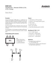
Error! Reference source not found.<br />
T delay<br />
T/2<br />
3T/8<br />
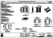
connectors, located at the opposite board sides. The PCB<br />
Gerber files are provided in the supporting archive<br />
together <strong>with</strong> PSoC project can be used for PCB routing<br />
reference. Figure 9 shows different <strong>Light</strong> <strong>Dimmer</strong> photos.<br />
Figure 9. <strong>Light</strong> <strong>Dimmer</strong> Photos<br />
a) Front View<br />
T/4<br />
T/8<br />
0<br />
0<br />
1<br />
2 3 4 5 6 7 8 9 10 11 12 13 14 15 16<br />
N slid<br />
b) Back View<br />
Figure 8. Triac Turning on Delay vs. Slider Position<br />
AC Mains Frequency Calibration<br />
There are several frequency AC standards in the world;<br />
some countries use 50Hz frequency, other 60Hz. For<br />
dimmer operation ability worldwide <strong>with</strong>out any manual<br />
adjustments, the additional calibration procedure is<br />
implemented. This procedure measures the actual AC<br />
mains frequency and calculates a scale coefficient to<br />
transform the lookup table array in the actual triac turning<br />
on delay values. The calibration procedure is initiated<br />
once after dimmer power up.<br />
Calibration takes in three stages. At first stage the duration<br />
of AC half period is measured using a CSD UM counter<br />
block. The 32 measurements are taken, averaged value is<br />
calculated. For this purpose a CSD is manually<br />
reconfigured by re-routing counter enable signal from<br />
comparator bus to zero-cross detector output.<br />
At the second stage the scale coefficient is calculated as<br />
relation of measured period (T C) to expected period (T C50)<br />
for 50Hz AC:<br />
K<br />
T<br />
T<br />
C<br />
= Equation 1<br />
C 50<br />
At third stage the triac turning on delay table (baConst) are<br />
scaled by coefficient K.<br />
<strong>Dimmer</strong> Mechanical Construction<br />
The dimmer is composed from two boards. The LED array<br />
and <strong>Capsense</strong> slider are placed on the first board, only<br />
SMT components are placed on this board. The reverse<br />
mount LEDs were placed in the slider segments.<br />
The power supply, zero-crossing detector, triac and screw<br />
power/lamp connectors were placed on second board. All<br />
through hole components were located on this board as<br />
well. The boards were connected together using 2<br />
Safety Warnings<br />
c) Side View<br />
The <strong>Light</strong> <strong>Dimmer</strong> does not have galvanic isolation from<br />
AC Mains Line. Plastic overlay should have thickness<br />
more than 2mm for user electrical shock preventing.<br />
Please newer touch PCB or dimmer components when<br />
supply voltage is applied. For device debugging and<br />
testing, please use the isolation transformer or galvanically<br />
isolated scope probes.<br />
Possible Modifications<br />
Some customers are willing optimizing the dimmer price<br />
for cost sensitive applications. The most expensive part is<br />
switching DC-DC converter. To reduce BOM amount, the<br />
power supply can be redesigned by using the simplest<br />
capacitive current source, see<br />
January 10, 2008 Document No. 001-08990 Rev. *B (AN# is same as last 5 digits of doc #.) 4