tm 09724a-10/1 us marine corps technical manual with ... - SpecOps
tm 09724a-10/1 us marine corps technical manual with ... - SpecOps
tm 09724a-10/1 us marine corps technical manual with ... - SpecOps

Create successful ePaper yourself
Turn your PDF publications into a flip-book with our unique Google optimized e-Paper software.
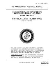
TM 09724A-<strong>10</strong>/1<br />
U. S. MARINE CORPS TECHNICAL MANUAL<br />
WITH COMPONENTS LIST<br />
OPERATOR’S MANUAL<br />
SUBMACHINE GUN, 9MM, MP5N (USMC)<br />
(<strong>10</strong>05-01-360-7146)<br />
THIS PUBLICATION IS REQUIRED FOR OFFICIAL USE OR FOR<br />
ADMINISTRATIVE OPERATIONAL PURPOSES. DISTRIBUTION IS<br />
LIMITED TO U.S. GOVERNMENT AGENCIES ONLY. OTHER<br />
REQUESTS FOR THIS DOCUMENT MUST BE REFERRED TO:<br />
COMMANDANT OF THE MARINE CORPS (ARE-B), WASHINGTON,<br />
D.C. 20380-0001.<br />
DESTRUCTION NOTICE FOR UNCLASSIFED, LIMITED DOCUMENTS,<br />
DESTROY BY ANY METHOD THAT WILL PREVENT DISCLOSURE OF<br />
THE CONTENTS OR RECONSTRUCTION OF THE DOCUMENT.<br />
FOR OFFICICAL USE ONLY AUGUST 1993<br />
PCN: 184 097241 00<br />
W/CHANGES 1 THRU 2 INCORPORATED<br />
CHANGES HAVE BEEN INCORPORATED<br />
AND ARE DENOTED BY A BAR (1 ) SYMBOL
TM<br />
09724A-<strong>10</strong>/1<br />
DEPARTMENT OF THE NAVY<br />
Headquarters, U. S. Marine <strong>corps</strong><br />
Washington, D. C. 20380-0001<br />
30 September 1993<br />
1. This Manual is effective upon receipt and contains Operator’s<br />
Instructions including Components List for Submachinegun, 9mm,<br />
MP5N (USMC) .<br />
2. Notice Of discrepancies or suggested changes should be<br />
forwarded on NAVMC <strong>10</strong>772 to: Commander, Marine Corps Logistics<br />
Bases (Code 850) , Albany, Georgia 31704-1128. In addition,<br />
notice of discrepancies should also be forwarded via Naval<br />
message or copy of submitted NAVMC <strong>10</strong>772 to:<br />
Commander, Marine Corps Systems Command<br />
2033 Barnett Ave, Suite 315<br />
Code (CBGI)<br />
Quantico, VA 22134-50<strong>10</strong><br />
BY DIRECTION OF THE COMMANDANT OF THE MARINE CORPS<br />
OFFICIAL:<br />
Colonel, USMC<br />
Director, Program Support<br />
Marine Corps Systems Command<br />
Distribution: 18409724<strong>10</strong>0
DEPARTMENT OF THE NAVY<br />
Headquarters, U.S. Marine Corps<br />
Washington, DC 20380-0001<br />
TM O9724A-<strong>10</strong>/1<br />
Change 2<br />
PCN 184 097241 02<br />
9 Aug<strong>us</strong>t 1996<br />
Encl: (1) Replacement Pages<br />
1. Purpose To transmit replacement pages to the basic <strong>manual</strong>,<br />
TM 09724A-<strong>10</strong>/1, dated Aug<strong>us</strong>t 1993, Operator's Manual Submachine Gun,<br />
9MM, MP5N (USMC) (<strong>10</strong>05-01-360-7146).<br />
2. Action. Remove present pages listed below and replace <strong>with</strong><br />
corresponding pages contained in the enclosure. Significant changes<br />
contained in the replacement pages of this change are denoted by a<br />
bar (1) symbol.<br />
REMOVE PAGES INSERT PAGES<br />
B-1 and B-2 B-1 and B-2<br />
3. Filing Instructions. This change transmittal page will be filed<br />
immediately following the signature page of the basic <strong>manual</strong>.<br />
BY DIRECTION OF THE COMMANDANT OF THE MARINE CORPS<br />
OFFICIAL<br />
Director, Logistics Data Management Division<br />
Marine Corps Logistics Bases<br />
Albany, Georgia<br />
DISTRIBUTION: PCN 184 097241 02<br />
18409724<strong>10</strong>2<br />
TM 09724A-<strong>10</strong>/1 1/(2 blank)
DEPARTMENT OF THE NAVY<br />
Headquarters, U.S. Marine Corps<br />
Washington, DC 20380-0001<br />
Encl: (1) Replacement Pages<br />
TM 09724A-<strong>10</strong>/1<br />
Change 1<br />
PCN 184 097241 01<br />
31 March 1996<br />
1. Purpose. To transmit replacement pages to the basic <strong>manual</strong>,<br />
TM 09724A-<strong>10</strong>/1, dated Aug<strong>us</strong>t 1993, Operator’s Manual Submachine Gun,<br />
9MM, MP5N (USMC) (<strong>10</strong>05-01-360-7146).<br />
2. Action. Remove present pages listed below and replace <strong>with</strong><br />
corresponding pages contained in the enclosure. Significant changes<br />
contained in the replacement pages of this change are denoted by a<br />
bar (#) symbol.<br />
REMOVE PAGES<br />
INSERT PAGES<br />
B-1 thru B-4 B-1 thru B-4<br />
4. Filing Instructions. This change transmittal page will be filed<br />
immediately following the signature page of the basic <strong>manual</strong>.<br />
BY DIRECTION OF THE COMMANDANT OF THE MARINE CORPS<br />
OFFICIAL<br />
Director, Logistics Data Management Division<br />
Marine Corps Logistics Bases<br />
Albany, Georgia<br />
DIsTRIBuTION : PCN 184 097241 01<br />
18409724<strong>10</strong>1<br />
TM 09724A-<strong>10</strong>/1 1/(2 blank)
TM 09724A-<strong>10</strong>/1<br />
TABLE OF CONTENTS<br />
Page<br />
LIST OF ILLUSTRATIONS . . . . . . . . . . . . . . . . . . . . . . . . . . . . . . . . . . . . vi<br />
SAFETY SUMMARY . . . . . . . . . . . . . . . . . . . . . . . . . . . . . . . . . . . . . .<br />
ix<br />
CHAPTER 1 GENERAL INFORMATION. . . . . . . . . . . . . . . . . . . . . . . . . 1-1<br />
Section I. INTRODUCTION . . . . . . . . . . . . . . . . . . 1-1<br />
1-1. SCOPE . . . . . . . . . . . . . . . . . . . . . . . . . . . . 1-1<br />
1-2. FORMS AND RECORDS . . . . . . . . . . . . . . . . . . . . . 1-1<br />
1-3. REPORTING EQUIPMENT IMPROVEMENT<br />
RECOMMENDATIONS (EAR ). . . . . . . . . . . 1-2<br />
1-4. CORROSION PREVENTION AND CONTROL (CPC) 1-2<br />
i
TM 09724A-<strong>10</strong>/1<br />
Page<br />
Section Il. EQUIPMENT DESCRIPTION . . . . . . . . . . . . . . . . 1-2<br />
1-5. GENERAL DESCRIPTION . . . . . . . . . . . . . . . . . . . . 1-2<br />
1-6, EQUIPMENT DATA . . . . . . . . . . . . . . . . . . . . . . . 1-6<br />
1-7. DESCRIPTION OF MAJOR COMPONENTS . . . . . . 1-9<br />
Section III. EQUIPMEN’T PREPARATION . . . . . . . . . . . . . . . . . . 1-<strong>10</strong><br />
1-8. CLEARING THE WEAPON . . . . . . . . . . . . . . . . . . 1-<strong>10</strong><br />
1-9. FIELD STRIPPING THE WEAPON. . . . . . . . . . . . . . 1-14<br />
1-<strong>10</strong>. ASSEMBLING THE WEAPON . . . . . . . . . . . . . . . . 1-21<br />
CHAPTER 2 OPERATING INSTRUCTIONS . . . . . . . . . . . . . . . . . . . . . . . . 2-1<br />
Section 1. PREVENTIVE MAINTENANCE CHECKS & SERVICES 2-1<br />
2-1. PREVENTIVE MAINTENANCE . . . . . . . . . . . . . . . . 2-1<br />
2-2. INSPECTING THE WEAPON . . . . . . . . . . . . . . . . . . 2-3<br />
ii
TM 09724A-<strong>10</strong>/1<br />
Page<br />
Section II. OPERATIONS . . . . . . . . . . . . . . . . . . . . . . . . . . . . . . 2-8<br />
2-3. LOADING THE WEAPON. . . . . . . . . . . . . . . . 2-8<br />
2-4. UNLOADING THE WEAPON . . . . . . . . . . . 2-12<br />
2-5. CYCLE OF OPERATION. . . . . . . . . . . . 2-14<br />
2-6. SIGHTING SYSTEM . . . . . . . . . . . 2-22<br />
2-7. TACTICAL LIGHTING SYSTEM . . . . . . . . . . . 2-27<br />
2-8. IMMEDIATE ACTION . . . . . . . . . . . . . . . . . . . 2-31<br />
CHAPTER 3 MAINTENANCE INSTRUCTIONS . . . . . . . . . . . . . . . 3-1<br />
Section I. LUBRICATION INSTRUCTIONS . . . . . . . . . . . . . . 3-1<br />
3-1. LUBRICATION THE WEAPON . . . . . . . . . . . 3-1<br />
Section II. TROUBLESHOOTING PROCEDURES . . . . . . . . . . . . . . . . 3-3<br />
3-2. TROUBLESHOOTING . . . . . . . . . . . . . 3-3<br />
iii
TM 09724A-<strong>10</strong>/1<br />
Page<br />
Section III. DISASSEMBLY PROCEDURES . . . . . . . . . . . .<br />
3-3. GENERAL . . . . . . . . . . . . . . . . . . . . . . . .<br />
3-4. BOLT CARRIER ASSEMBLY . . . . . . . . . . . . .<br />
3-5. PISTOL GRIP AND TRIGGER MECHANISM<br />
ASSEMBLY . . . . . . . . . . . . . . . . . . . . . . .<br />
3-6. MAGAZINE ASSEMBLY. . . . . . . . . . . . . . . . . . .<br />
3-7. HANDGUARD AND TACTICAL LIGHT ASSEMBLY ,<br />
3-8. CLEANING THE WEAPON. . . . . . . . . . . .<br />
3-7<br />
3-7<br />
3-9<br />
3-12<br />
3-15<br />
3-18<br />
3-20<br />
Section IV. REASSEMBLY PROCEDURES . . . . . . . . . . . . . . . . . 3-25<br />
3-9. HANDGUARD AND TACTICAL LIGHT ASSEMBLY . 3-25<br />
3-<strong>10</strong>. PISTOL GRIP AND TRIGGER MECHANISM<br />
ASSEMBLY . . . . . . . . . . . . . . . . . . . . . . 3-25<br />
3-11. BOLT CARRIER ASSEMBLY . . . . . . . . . . . . . . . . 3-26<br />
3-12. REASSEMBLING THE WEAPON . . . . . . . . . . . . . . 3-27<br />
3-13. MAGAZINE ASSEMBLY . . . . . . . . . . . . . . . 3-32<br />
3-14. FUNCTIONAL CHECK . . . . . . . . . . . . . . . . . . . 3-32<br />
iv
TM 09724A-<strong>10</strong>/1<br />
CHAPTER 4 AMMUNITION . . . . . . . . . . . . . . . . . . . . . . . . . . . . . . . 4-1<br />
Page<br />
Section I. AMMUNITION INSTRUCTIONS . . . . . . . . . . . . 4-1<br />
4-1. AUTHORIZED AMMUNITION . . . . . . . . . 4-1<br />
Section II. AMMUNITION LOGISTICS . . . . . . . . . . . . . 4-3<br />
4-2. CARE, HANDLING, AND STORAGE . . . . . . . . . . 4-3<br />
APPENDIX A. REFERENCES . . . . . . . . . . . . . . . . . . . . . . . . . . . A-1<br />
APPENDIX B. COMPONENTS LIST . . . . . . . . . . . . . . . . . . . . . . . . . . . . B-1<br />
v
TM 09724A-<strong>10</strong>/1<br />
LIST OF ILLUSTRATIONS<br />
Figure Title Page<br />
1-1. MP5-N Submachine Gun- Left Side . . . . . . . . . . . . . . . . . . . . . . . . . . . 1-4<br />
1-2. MP5-N Submachine Gun -Right Side . . . . . . . . . . . . . . . . . . . . . . . . . 1-5<br />
1-3. MP5-N Submachine Gun - Major Components . . . . . . . . . . . 1-8<br />
1-4. Selector Lever . . . . . . . . . . . . . . . . . . . . . . . . . . . . . . . . . . . . . 1-11<br />
-5. Removing The Magazine . . . . . . . . . . . . . . . . . . . . . . . . . . . . . . . . . . 1-12<br />
1-6. Pulling The Charging Handle. . . . . . . . . . . . . . . . . . . . . . . . . . . . . . . 1-13<br />
1-7. Field Stripped . . . . . . . . . . . . . . . . . . . . . . . . . . . . . . . . . . . . . . . . 1-15<br />
l-8. Removing The Buttstock . . . . . . . . . . . . . . . . . . . . . . . . . . . . . . . . . . 1-17<br />
l-9. Removing The Bolt Carrier Assembly . . . . . . . . . . . . . . . . . . . . . . . . . . 1-18<br />
l-l0. Removing Trigger Mechanism Pin . . . . . . . . . . . . . . . . . . . . . . . . . . . 1-19<br />
l-11. Removing Handguard Pin . . . . . . . . . . . . . . . . . . . . . . . . . . . . . . . . . 1-20<br />
2-1. Loading And Unloading The Magazine . . . . . . . . . . . . . . . . . . . . . . . . . . 2-9<br />
2-2. inserting The Magazine . . . . . . . . . . . . . . . . . . . . . . . . . . . . . . . . . . . . 2-<strong>10</strong><br />
vi
Figure<br />
Title<br />
TM 09724A-<strong>10</strong>/l<br />
Page<br />
2-3. Bolt In The Locked Position. . . . . . . . . . . . . . . . . . . . . . . . . . .<br />
2-4. Trigger Mechanism . . . . . . . . . . . . . . . . . . . . . . . . . . . . . . . . . .<br />
2-5. Bolt In The Unlocked Position . . . . . . . . . . . . . . . . . . . . . . .<br />
2-6. Extractor . . . . . . . . . . . . . . . . . . . . . . . . . . . . . . . . . . . . . . . . . . . . . . . . . . . . . . . .<br />
2-7. Ejector . . . . . . . . . . . . . . . . . . . . . . . . . . . . . . . . . . . . . . . . . . . . . . . . . . . . . . . .. . .<br />
2-8. Elevation Adj<strong>us</strong><strong>tm</strong>ent . . . . . . . . . . . . . . . . . . . . . . . . . . . . . . .<br />
2-9. Loosening The Clamping Screw . . . . . . . . . . . . . . . . . . . . . . . . . . .<br />
2-<strong>10</strong>. Rotating The Adj<strong>us</strong>ting Screw . . . . . . . . . . . . . . . . . . . . . . . . . . . . . . . . . .<br />
2-11. Handguard And Tactical Lighting System . . . . . . . . . . . . . . . . . . .<br />
2-12. Lighting Components.. . . . . . . . . . . . . . . . . . . . . . . . . . . .<br />
2-15<br />
2-17<br />
2-18<br />
2-20<br />
2-21<br />
2-23<br />
2-25<br />
2-26<br />
2-28<br />
2-30<br />
3-1. Removing Bolt Head And Locking Piece . . . . . . . . . . . . . . . . .<br />
3-2. Disassembled Bolt Head . . . . . . . . . . . . . . . . . . . . . . . . . . . . . . . .<br />
3-3. Disassembled Pistol Grip And Trigger Mechanism . . . . . . . . . . . .<br />
3-4. Disassembled Trigger Mechanism And Selector Lever . . . . . . . . . .<br />
3-5. Disassembled Magazine Assembly . . . . . . . . . . . . . . . . . . . . .<br />
3-<strong>10</strong><br />
3-11<br />
3-13<br />
3-14<br />
3-17<br />
vii
TM 09724A-<strong>10</strong>/1<br />
Figure Title Page<br />
3-6. Disassembled Handguard And Tactical Light Assembly . . . . . . . . . . . 3-19<br />
3-7. Flash Suppressor . . . . . . . . . . . . . . . . . . . . . . . . . . . . . . . . 3-28<br />
3-8. Thread Cap And Thread Cupholder . . . . . . . . . . . . . . . 3-29<br />
3-9. Multi-Purpose Sling . . . . . . . . . . . . . . . . . . . . . . . . . . . . . . . . . 3-30<br />
3-<strong>10</strong>. Sling Connection Points. . . . . . . . . . . . . . . . . . . . . . . 3-31<br />
viii
TM 09724A-<strong>10</strong>/1<br />
SAFETY SUMMARY<br />
The following WARNINGS and CAUTIONS appear on the page referenced and are listed here<br />
for emphasis.<br />
Make certain fingers are outside of the trigger guard and<br />
the weapon is pointed in a safe direction at all times. (Page 1-<strong>10</strong>)<br />
Make certain the weapon is cleared. (Page 1-14, 3-7, 3-33)<br />
ix
TM 09724A-<strong>10</strong>/1<br />
Before starting an inspection, be sure to clear the weapon. Do not actuate<br />
the trigger until the weapon has been cleared. Inspect the clamber to be<br />
sure it is empty and that there are no obstructions in the barrel. (Page 2-3)<br />
Never try to force a cartridge to chamber. If the bolt does not fully<br />
close, release the magazine, clear the weapon, and check for obstructions,<br />
but do not attempt to fire. Serio<strong>us</strong> injury could result. (Page 2-11)<br />
x
TM 09724A-<strong>10</strong>/1<br />
After the weapon is unloaded, and <strong>with</strong> the charging handle to the rear,<br />
always physically check the chamber for ammunition to preclude injury<br />
from an accidental discharge. (Page 2-13)<br />
The battery <strong>us</strong>ed in the Tactical Light System is a lithium battery. Battery can<br />
explode or ca<strong>us</strong>e burns if disassembled, shorted, recharged or exposed to fire or<br />
high temperatures. Turn old battery in to the Unit Armory. (Page 2-27)<br />
xi
TM 09724A-<strong>10</strong>/1<br />
When disassembling spring loaded parts, point components away<br />
from face/eyes to avoid possible injury if parts fly free. (Page 3-9)<br />
When disassembling magazine, point the bottom of the magazine away from face.<br />
(Page 3-15)<br />
xii
TM 09724A-<strong>10</strong>/1<br />
Double hearing protection should be worn when firing since harmful<br />
levels of noise are generated. (Page 3-34)<br />
Do not fire corroded or dented cartridges <strong>with</strong> loose bullets,<br />
or any other defective rounds detected by visual inspection. (Page 4-2)<br />
xiii
TM 09724A-<strong>10</strong>/1<br />
Do not leave cartridges in the magazine for extended periods of time<br />
since this will ca<strong>us</strong>e the spring to lose tension and may ca<strong>us</strong>e a<br />
malfunction. (Page 2-13)<br />
The battery <strong>us</strong>ed in the Tactical Light System is very powerful. Be sure that the<br />
switch is not touching anything when the weapon is stored. If the lamp is turned<br />
on while in a case or other container, the lamp can overheat and damage the<br />
tactical light or surrounding materials. (Page 2-29)<br />
xiv
TM 09724A-<strong>10</strong>/1<br />
Use only authorized lubrication. Do not mix lubrication. (Page 3-1)<br />
Further disassembly of trigger mechanism should only be performed<br />
by ordnance personnel. (Page 3-12)<br />
xv
TM 09724A-<strong>10</strong>/1<br />
Always clean the weapon from the chamber end. Never reverse the direction of<br />
the bore br<strong>us</strong>h inside the bore. This damages the bore br<strong>us</strong>h and could damage<br />
the bore as well. (Page 3-21)<br />
Do NOT allow fluid to enter the Tactical Light Assembly.<br />
This may damage components and ca<strong>us</strong>e light failure. (Page 3-24)<br />
xvi
TM 09724A-<strong>10</strong>/1<br />
CHAPTER 1<br />
GENERAL INFORMATION<br />
1-1. SCOPE<br />
Section I. INTRODUCTION<br />
a. Type of Manual. Operators Manual featuring organizational maintenance<br />
procedures (First through Seeond Echelons) for the Submachine Gun, 9 mm, MP5N.<br />
b. Equipment Name and Model Number. The MP5N Submachine Gun (SMG) is<br />
equipped <strong>with</strong> the Tactical Lighting System and is a special operations weapon for combat in<br />
close quarters utilizing 9 mm ammunition. The MP5N provides for either single shots or full<br />
automatic fire; a 30-round magazine capacity; and has facilities for firing <strong>with</strong> a sound<br />
suppressor.<br />
1-2. FORMS AND RECORDS. Marine Corps forms and procedures <strong>us</strong>ed for equipment<br />
maintenance will be those prescribed in the current edition of TM 4700-15/1, Equipment Record<br />
Procedures. Weapons Record Book. Part II, will also be maintained.<br />
l-l
TM 09724A-<strong>10</strong>/1<br />
1-3. REPORTING EQUIPMENT IMPROVEMENT RECOMMENDATIONS (EIR). If<br />
your submachine gun needs improvement, let <strong>us</strong> know. Send <strong>us</strong> an EIR directly to:<br />
Commander. Marine Corps Logistics Base (Code 850), 814 Radford Blvd, Albany, Georgia<br />
31704-5000. Also, respond to MARCORSYSCOM (Code CBGI) <strong>with</strong> a copy of the EIR. You,<br />
the <strong>us</strong>er. are the only one who can tell <strong>us</strong> what you don’t like about your equipment. Let <strong>us</strong><br />
know why you don’t like the design or performance,<br />
1-4. CORROSION PREVENTION AND CONTROL (CPC). Corrosion Control for Marine<br />
Corps Ground Equipment is prescribed in the current edition of TM 3050-25/2. If a recurrent<br />
corrosion problem is identified, h should be reported on SF 368 (Product Quality Deficiency<br />
Report (PQDR)) in accordance <strong>with</strong> guidance contained in Marine Corps Order 4855.<strong>10</strong>.<br />
Section II. EQUIPMENT DESCRIPTION<br />
1-5. GENERAL DESCRIPTION. The MP5N Submachine Gun is an automatic small arms<br />
weapon. It permits either single shots or full-automatic tire to be fired from all positions. The<br />
MP5N is recoil-operated, <strong>with</strong> fixed barrel and delayed roller-locked bolt system. The high<br />
accuracy of the MP5N results from the fact that the submachine gun tires from the closed bolt<br />
position, in conjunction <strong>with</strong> the recoil operated delayed roller locked bolt system. The delayed<br />
1-2
TM 09724A-<strong>10</strong>/1<br />
roller locked bolt system also allows the MP5N to be controlled more easily when firing fullautomatic<br />
fire. MP5N components are listed in Appendix B.<br />
a. The left side of the MP5N, Figure 1-1, reveals flash suppressor (1), front sight (2),<br />
charging handle (3), serial number location (4), sling connection (5), locking catch (6). magazine<br />
catch (7), and hand guard (8).<br />
b. The right side of the MP5N, Figure 1-2, reveals rear sight (1), pressure switch for<br />
tactical light (2), tactical light (3), magazine (4), magazine release button (5). magazine release<br />
lever (6), trigger (7), selector lever (8), and retractable butt stock (9).<br />
1-3
TM 09724A-<strong>10</strong>/1<br />
Figure 1-1. MP5N Submachine Gun - Left Side<br />
l-l
TM 09724A-<strong>10</strong>/1<br />
Figure 1-2. MP5N Submachine Gun - Right Side<br />
1-5
TM 09724A-<strong>10</strong>/1<br />
1-6. EQUIPMENT DATA<br />
Table 1-1. Specifications and Capabilities<br />
1-6
TM 09724A-<strong>10</strong>/1<br />
1-7
TM 09724A-<strong>10</strong>/1<br />
Figure 1-3. MP5N Submachine Gun - Major Components<br />
Numbers are keyed to the text on pages 1-9 and 1-<strong>10</strong><br />
1-8
TM 09724A-<strong>10</strong>/1<br />
1-7. DESCRIPTION OF MAJOR COMPONENTS. (Refer to Figure 1-3)<br />
(1) BARREL AND RECEIVER ASSEMBLY. The receiver connects the barrel, flash<br />
suppressor, charging handle, and front and rear sights. In addition, all assemblies are either<br />
contained in the receiver or attached to it. The barrel is press-fitted into the barrel extension and<br />
fixed in place by means of pins.<br />
(2) BOLT CARRIER ASSEMBLY. The bolt carrier assembly is ho<strong>us</strong>ed and guided in the<br />
receiver; in conjunction <strong>with</strong> the recoil spring, it feeds and fires the cartridge, extracts and ejects<br />
the empty cartridge ease after firing, and cocks the hammer.<br />
(3) RETRACTABLE BUTTSTOCK ASSEMBLY. The two guide rails on either side of the<br />
buttstock are guided in grooves on the receiver. They are secured by a locking catch in both the<br />
retracted and extended positions. A sling holder is attached to the back plate.<br />
(4) PISTOL GRIP AND TRIGGER MECHANISM ASSEMBLY. The pistol grip is hinged to<br />
the receiver and can be swung down and removed from it; it contains the trigger mechanism,<br />
<strong>with</strong> components of the trigger and safety, The safety axle connects the trigger mechanism to<br />
the pistol grip. The selector lever is ambidextro<strong>us</strong>.<br />
1-9
TM 09724A-<strong>10</strong>/1<br />
(5) MAGAZINE ASSEMBLY. The magazine is attached to the receiver through the magazine<br />
well and is held in place by the magazine catch. The forward motion of the bolt carrier<br />
assembly strips the cartridge from the magazine and feeds it into the chamber.<br />
(6) HANDGUARD ASSEMBLY AND TACTICAL LIGHT. The tactical light combines<br />
ho<strong>us</strong>ing. lamp. switch, batteries and handguard into a single unit. The handguard encircles the<br />
barrel from below. It is attached to the weapon by a locking pin.<br />
Section III. EQUIPMENT PREPARATION<br />
1-8. CLEARING THE WEAPON. Always assume every weapon to be loaded until you have<br />
personally determined it to be safe.<br />
Make certain fingers are outside of the trigger guard and the weapon is<br />
pointed in a safe direction at all times.<br />
1-<strong>10</strong>
TM 09724A-<strong>10</strong>/1<br />
a. On Safe. Rotate the ambidextro<strong>us</strong> selector lever, Figure 1-4, to the SAFE position.<br />
Figure 1-4. Selector Lever<br />
1-11
TM 09724A-<strong>10</strong>/1<br />
b. Remove Magazine. P<strong>us</strong>h either the magazine release lever (1), Figure l-5,or the<br />
magazine release button (located on the right side of the weapon), to release the magazine from<br />
the magazine catch.<br />
Figure 1-5. Removing The Magazine<br />
1-12
TM 09724A-<strong>10</strong>/1<br />
c. Charging Handle. Pull the charging handle (1), Figure 1-6, to the rear and lock it<br />
into the recess (2). Watch for live round or empty cartridge to be ejected.<br />
Figure 1-6. Pulling The Charging Handle<br />
1-13
TM 09724A-<strong>10</strong>/1<br />
d. Inspect Chamber. Inspect chamber for presence of live round or empty<br />
cartridge. Visually inspect the chamber through the ejection port and physically insert finger to<br />
check for the presence of cartridge case in chamber. Remove any live rounds or empty cartridge<br />
from the chamber or from <strong>with</strong>in the weapon.<br />
1-9. FIELD STRIPPING THE WEAPON. Field strip the weapon into its seven major groups<br />
as shown in Figure 1-7. Barrel and Receiver Assembly (1), Bolt Assembly (2), Retractable<br />
Buttstock Assembly (3), Pistol Grip and Trigger Mechanism Assembly (4), Magazine Assembly<br />
(5), Handguard and Tactical Light Assembly (6), and Flash Suppressor (7).<br />
Make certain the weapon is cleared.<br />
a. Rotate the selector lever to SAFE and remove the magazine.<br />
b. Place charging handle and bolt group in the forward position.<br />
1-14
TM 09724A-<strong>10</strong>/1<br />
Figure 1-7. Field Stripped<br />
1-15
TM 09724A-<strong>10</strong>/1<br />
Do NOT lay the locking pins down. To prevent misplacing them, place<br />
them back in the holes from which they came once the assembly group<br />
has been removed.<br />
c. Remove buttstock locking pin (1), Figure 1-8, by p<strong>us</strong>hing from right to left.<br />
Remove buttsktock {2).<br />
d. Rotate pistol grip and trigger mechanism assembly downward away from receiver<br />
and slide the bolt carrier assembly (1), Figure 1-9, out of the back of the receiver.<br />
e. Remove trigger mechanism locking pin (l), Figure 1-<strong>10</strong>, and remove pistol grip<br />
and trigger mechanism.<br />
f. Remove handguard locking pin (l), Figure 1-11, and remove handguard and<br />
tactical light assembly.<br />
1-16
TM 09724A-<strong>10</strong>/1<br />
Figure 1-8. Removing The Buttstock<br />
1-17
TM 09724A-<strong>10</strong>/1<br />
Figure 1-9. Removing The Bolt Carrier Assembly<br />
1-18
TM 09724A-<strong>10</strong>/1<br />
Figure 1-<strong>10</strong>. Removing Trigger Mechanism Pin<br />
1-19
TM 09724A-<strong>10</strong>/1<br />
Figure 1-11. Removing Handguard Pin<br />
1-20
TM 09724A-<strong>10</strong>/1<br />
1-<strong>10</strong>. ASSEMBLING THE WEAPON. Once cleaning and/or repairs are accomplished,<br />
reassemble the weapon in the following manner:<br />
a. Slide handguard and tactical light assembly into place.<br />
b. Align the pin hole and install the handguard locking pin (1), Figure 1-11.<br />
c. Cock [he hammer back and install the pistol grip and trigger mechanism assembly.<br />
d. Align the pin hole and install the trigger mechanism locking pin (1), Figure 1-<strong>10</strong>.<br />
Allow the pistol grip and trigger mechanism assembly to pivot downward away from the receiver<br />
e. Slide the bolt carrier assembly (1), Figure 1-9, back into the receiver.<br />
f. Swing the pistol grip and trigger mechanism assembly up and hold in position.<br />
g. P<strong>us</strong>h the retractable buttstock assembly (2), Figure 1-8, over the rear flap of the<br />
pistol grip and into position on the receiver.<br />
1-21
TM 09724A-<strong>10</strong>/1<br />
h. Align the pin hole and install the buttstock locking pin (1).<br />
i. Cycle the charging handle back and forth several times to ensure the weapon is<br />
properly assembled.<br />
j. Pull the trigger.<br />
k. Rotate the selector lever, Figure 1-4, to SAFE.<br />
1-22
TM 09724A-<strong>10</strong>/1<br />
CHAPTER 2<br />
OPERATING INSTRUCTIONS<br />
Section I. PREVENTIVE MAINTENANCE CHECKS AND SERVICES<br />
2-1. PREVENTIVE MAINTENANCE<br />
a. Before Firing. Always clean and inspect your weapon prior to firing. Firing a<br />
weapon <strong>with</strong> a dirty bore or chamber may ca<strong>us</strong>e a weapon failure during a critical moment,<br />
Apply a light coat of Cleaner, Lubricant and Preservative (CLP) on all moving parts,<br />
b. After Firing. The MP5N m<strong>us</strong>t be cleaned after it haa been fired beca<strong>us</strong>e firing<br />
produces deposits of primer fouling. powder ashes, carbon and metal fouling. Although modem<br />
ammunition has a non-corrosive primer which makes cleaning easier, the primer still leaves a<br />
deposit which may collect moisture and promote r<strong>us</strong>t if not removed. The weapon m<strong>us</strong>t be<br />
cleaned <strong>with</strong>in a reasonable interval, a matter of hours after firing. Repeated firing will not<br />
injure the weapon if it were properly cleaned prior to the first round. After firing the weapon,<br />
clean for three consecutive days <strong>us</strong>ing the items listed in Appendix B. Following the three<br />
consecutive days of cleaning, check the weapon the next several days for fouling by running a<br />
clean swab through the bore.<br />
2-1
TM 09724A-<strong>10</strong>/1<br />
(1) Clean the bore and chamber. Thoroughly clean the bolt and trigger<br />
mechanism, removing all carbon deposits. Repeat this cleaning for three consecutive days, or<br />
until there is no longer any evidence of fouling in the bore.<br />
(2) After the fourth cleaning following firing, and if no additional tiring is<br />
anticipated <strong>with</strong>in the next 24 hours. <strong>us</strong>e clean, dry swabs to thoroughly dry bore and chamber.<br />
Then, <strong>us</strong>ing clean swabs which have been dipped in CLP and the excess wrung out, apply a light<br />
film to the bore and chamber.<br />
(3) Remove the bolt head from the bolt carrier assembly and thoroughly<br />
clean its interior and exterior. Remove all brass fouling and powder residue from the face of the<br />
bolt. being especially alert to fouling on the bolt face and the firing pin hole.<br />
(4) Thoroughly dry all other components and apply a light coating of CLP<br />
or another approved lubricant.<br />
c. Daily Service. As part of daily service, inspect the bore and chamber, and clean<br />
component parts of the weapon. Wipe entire weapon thoroughly, dry, and relubricate.<br />
2-2
TM 09724A-<strong>10</strong>/1<br />
d. Extended Periods. For periods greater than two weeks, renew the oil film in the<br />
bore and chamber every four days. If the weapon is not being fired, apply a medium coat of<br />
CLP to provide extra lubrication and corrosion protection.<br />
2-2. INSPECTING THE WEAPON. Inspect all assemblies for missing, broken, or loose<br />
parts. Inspect parts for cracks, dents, burrs, excessive wear, r<strong>us</strong>t, or corrosion. Make sure all<br />
items are cleaned and lubricated. Repair or replace defective pans, or evacuate the weapon to<br />
intermediate maintenance if repair or replacement is not authorized at organizational<br />
maintenance. Field strip the weapon (pars 1-9, page 1-14) and inspect as follows:<br />
Before starting an inspection, be sure to clear the weapon. Do not<br />
actuate the trigger until the weapon has been cleared. Inspect the<br />
chamber to be sure it is empty and that there are no obstructions in the<br />
barrel.<br />
2-3
TM 09724A-<strong>10</strong>/1<br />
lTEM INSPECTED<br />
PROCEDURE / CONDITION<br />
Barrel and Receiver Assembly:<br />
Barrel<br />
Sighting<br />
Charging Handle<br />
M<strong>us</strong>t not have powder residue or fouling. Special<br />
attention should be paid to cleaning and oiling the<br />
receiver, barrel extension and barrel.<br />
Front and rear sights should be securely seated.<br />
Sight apertures m<strong>us</strong>t not be dented.<br />
Check for damages as well as serviceability.<br />
Magazine Catch<br />
Check for smooth operation.<br />
2-4
TM 09724A-<strong>10</strong>/1<br />
ITEM INSPECTED<br />
PROCEDURE / CONDITION<br />
Bolt Carrier Assembly:<br />
Bolt<br />
Manually work the bolt head and locking piece in and<br />
out, feeling for any roughness, which may indicate<br />
wear, corrosion, or dirt/grit in the earner.<br />
Firing Pin<br />
P<strong>us</strong>h the bolt into the carrier and inspect for firingpin<br />
protr<strong>us</strong>ion. Check firing-pin hole for<br />
erosion/pitting.<br />
Extractor<br />
Check to ensure it is under spring tension, and is not<br />
chipped or worn.<br />
2-5
TM 09724A-<strong>10</strong>/1<br />
ITEM INSPECTED<br />
PROCEDURE / CONDITION<br />
Pistol Grip and Trigger<br />
Mechanism Assembly:<br />
Check components for dents and wear. Also, check<br />
trigger mechanism and selector lever for smooth<br />
operation.<br />
Retractable Buttstock Assembly:<br />
Check for dents and wear. Check for proper function<br />
of the clamping lever.<br />
Magazine Assembly:<br />
Check for dents and serviceability of the follower.<br />
Check for correct position of cartridges in the<br />
magazine lips and if the magazine is securely seated<br />
in the magazine catch.<br />
2-6
TM 09724A-<strong>10</strong>/1<br />
ITEM INSPECTED<br />
PROCEDURE / CONDITION<br />
Handguard and Tactical Light:<br />
(Standard and Drop Light models)<br />
Check for cracks. Ensure locking pin is seated<br />
securely. Check battery in tactical light.<br />
Multi-Purpose Sling: Should be kept clean. Also, check for brittleness and<br />
function.<br />
Flash Suppressor:<br />
Should be kept clean. Also, check for dents and the<br />
proper fit on the barrel.<br />
2-7
TM 09724A-<strong>10</strong>/1<br />
2-3. LOADING THE WEAPON.<br />
Section II. OPERATIONS<br />
a. Magzine. Using the appropriate ammunition, load the magazine. Hold the<br />
magazine in one hand: <strong>with</strong> the other hand, place the cartridge on the magazine follower, Figure<br />
2-1, and <strong>with</strong> slight pressure <strong>with</strong> the thumb, p<strong>us</strong>h the cartridge under the magazine lip. Ensure<br />
that all cartridges are p<strong>us</strong>hed all the way to the rear of the magazine.<br />
b. MP5N. With the selector lever on SAFE and prior to inserting the magazine,<br />
grasp the charging handle and dry-cycle the weapon several times (work the bolt all the way<br />
back and forth). This will determine if the bolt carrier assembly is functioning properly.<br />
(1) Insert the magazine into the magazine well. Tug on the magazine to<br />
ensure it is locked in place. The magazine should lock <strong>with</strong> an audible click as it engages the<br />
magazine catch (1) Figure 2-2.<br />
(2) With the selector lever on SAFE and the muzzle pointed in a safe<br />
direction, pull the charging handle <strong>10</strong> the rear and allow it to snap forward. The weapon loads<br />
and locks a cartridge into the chamber for firing.<br />
2-8
TM 09724A-<strong>10</strong>/1<br />
Figure 2-1. Loading And Unloading The Magazine<br />
2-9
TM 09724A-<strong>10</strong>/1<br />
Figure 2-2. Inserting The Magazine<br />
2-<strong>10</strong>
TM 09724A-<strong>10</strong>/1<br />
Never try to force a cartridge to chamber. If the bolt does not fully<br />
close, release the magazine, clear the weapon, and checks for<br />
obstructions, but do not attempt to tire. Serio<strong>us</strong> injury could result.<br />
d. Beca<strong>us</strong>e the weapon has a substantial recoil, the shooter m<strong>us</strong>t be positioned<br />
squarely behind the weapon, otherwise. accuracy may be diminished, injury or discomfort may<br />
result, or the action may fail to cycle correctly.<br />
2-11
TM 09724A-<strong>10</strong>/1<br />
e. With the selector lever turned to either the SINGLE or FULL AUTO<br />
(full-automatic) position, (Figure 1-4 on page 1-11), the MP5N may now be fired. The weapon<br />
will fire one round for each squeeze of the trigger when the selector lever is in the SINGLE fire<br />
mode, or fire continuo<strong>us</strong>ly <strong>with</strong> one pull of the trigger when the selector lever is in the FULL<br />
AUTO tire mode. or until the magazine and chamber are empty.<br />
f. If a cartridge or round jams in the chamber and can not be removed by immediate<br />
action, evacuate the weapon to the next higher echelon of maintenance.<br />
2-4. UNLOADING THE WEAPON<br />
a. MP5N. Rotate the selector lever to SAFE (Figure 1-4 on page 1-11). P<strong>us</strong>h the<br />
magazine release lever forward or depress the magazine release button to remove the magazine<br />
(Figure 1-5 on page 1-12). Engage the charging handle in the recess, which will eject any<br />
cartridge still chambered. The bolt does NOT automatically remain to the rear when the weapon<br />
or magazine is empty. After the MP5N is unloaded, and <strong>with</strong> the charging handle to the rear,<br />
look into the chamber and feel <strong>with</strong> a finger to make certain the breech area and chamber are<br />
empty.<br />
2-12
TM 09724A-<strong>10</strong>/1<br />
b. Magazine. To unload the magazine, hold it in the left hand <strong>with</strong> the bullet end of<br />
the cartridge pointing towards your right band. With the right thumb, p<strong>us</strong>h the cartridge out of<br />
the magazine and into the right palm.<br />
After the weapon is unloaded, and <strong>with</strong> the charging handle to the<br />
rear, always physically check the chamber for ammunition to preclude<br />
injury from an accidental discharge.<br />
Do not leave cartridges in the magazine for extended periods of time<br />
since this will ca<strong>us</strong>e the spring to lose tension and may ca<strong>us</strong>e a<br />
malfunction.<br />
2-13
TM 09724A-<strong>10</strong>/1<br />
2-5. CYCLE OF OPERATION. The cycle of operation for the MP5N is broken down into<br />
eight basic steps, and more than one step may occur at the same time.<br />
a. Feeding. The force of the recoil spring p<strong>us</strong>hes the bolt forward, toward the barrel<br />
extension, stripping a cartridge from the magazine and loading it into the chamber (by hand<br />
<strong>us</strong>ing the charging handle when first loading and then by semi-automatic action thereafter).<br />
b. Chambering. The bolt forces the round folly into the firing chamber, and the<br />
extractor snaps over the case rim. Blockages (dirt or debris) can prevent full cambering, as can<br />
dirty, bent, dented, or otherwise faulty ammunition.<br />
c. Locking. The weapon relies on a delayed roller-locked bolt system. During<br />
cambering the bolt head (1), Figure 2-3, enters the barrel extension (2). The angled shoulders<br />
of the locking piece forces the locking rollers (3) into the contours of the barrel extension, to<br />
lock the weapon. The firing pin (4), is now in positioned behind the cartridge for firing.<br />
2-14
TM 09724A-<strong>10</strong>/1<br />
Figure 2-3. Bolt In The Locked Position<br />
2-15
TM 09724A-<strong>10</strong>/1<br />
d. Firing. When the trigger pivots on its axle, the back of the sear (1), Figure 2-4.<br />
rises, ca<strong>us</strong>ing the front of the sear to lower. This action removes the sear from the notch in the<br />
hammer (2), ca<strong>us</strong>ing the hammer to pivot on its axle. As a result of spring tension, the hammer<br />
is allowed to strike the fining pin (3) and ignite the primer of the cartridge,<br />
e. Unlocking. When the cartridge is fired, gas pressure exerts a thr<strong>us</strong>t on the bolt<br />
head face. The bolt head carrier (1), Figure 2-5, carries the bolt to the rear to unseat and<br />
compress the locking rollers. The balanced angular ratio of the locking piece (2), and the<br />
locking rollers ca<strong>us</strong>es a delayed recoil movement of the bolt head, th<strong>us</strong> guaranteeing that the bolt<br />
keeps the barrel locked until the bullet has left the muzzle. The bolt head earner continues<br />
rearward until it contacts the fact of the hammer, forcing the hammer to cock and the recoil<br />
spring to be compressed.<br />
2-16
TM 09724A-<strong>10</strong>/1<br />
Figure 2-4. Trigger Mechanism<br />
2-17
TM 09724A-<strong>10</strong>/1<br />
Figure 2-5. Bolt In The Unlocked Position<br />
2-18
TM 09724A-<strong>10</strong>/1<br />
f. Extraction. With the extractor (1). Figure 2-6, crimped around the extracting<br />
groove on the cartridge case. the rearward movement of the bolt head carrier allows the empty<br />
cartridge to be removed from the barrel extension during the recoil and compression of the<br />
locking rollers (2).<br />
g. Ejection. As soon as the fired case has been extracted and has cleared the rear of<br />
the barrel extension, it is expelled from the weapon by the ejector (1). Figure 2-7, which is<br />
located <strong>with</strong>in the trigger mechanism.<br />
h. Cocking. As the bolt recoils to the rear, it rides the hammer back and down<br />
ca<strong>us</strong>ing the hammer to engage the sear (1), Figure 2-4.<br />
2-19
TM 09724A-<strong>10</strong>/1<br />
Figure 2-6. Extractor<br />
2-20
TM 09724A-<strong>10</strong>/1<br />
Figure 2-7. Ejector<br />
2-21
TM 09724A-<strong>10</strong>/1<br />
2-6. SIGHTING SYSTEM. The MP5N is equipped <strong>with</strong> iron sights consisting of a rigid front<br />
sight <strong>with</strong> a tritium dot and an adj<strong>us</strong>table diopter-rotary rear sight <strong>with</strong> four different aperture<br />
openings.<br />
a. Elevation Adj<strong>us</strong><strong>tm</strong>ent<br />
(1) Insert elevation adj<strong>us</strong><strong>tm</strong>ent tool (1), Figure 2-8, into the rear sight<br />
cylinder (2), in such a manner that the prongs of the tool engage the two detents in the cylinder,<br />
which contain the catch bolts. Press phillips-head screwdriver downward into the adj<strong>us</strong><strong>tm</strong>ent<br />
tool and hold firmly.<br />
(2) Rotate rear sight cylinder <strong>manual</strong>ly in the desired direction (rotating<br />
clockwise lowers the strike of the round 1.4 cm {0.55 inches) per click at a range of 25 meters,<br />
rotating counter-clockwise raises it correspondingly).<br />
(3) After performing the correction, <strong>with</strong>draw phillips-head screwdriver<br />
and remove elevation adj<strong>us</strong><strong>tm</strong>ent tool. The catch bolts will then re-engage in the splines.<br />
(4) After performing the elevation adj<strong>us</strong><strong>tm</strong>ent, re-set the rear sight cylinder<br />
to the desired aperture.<br />
2-22
TM 09724A-<strong>10</strong>/1<br />
Figure 2-8. Elevation Adj<strong>us</strong><strong>tm</strong>ent<br />
2-23
TM 09724A-<strong>10</strong>/1<br />
b. Windage Adj<strong>us</strong><strong>tm</strong>ent<br />
(1) Correction for left-hand deviation: Loosen clamping screw (1), Figure<br />
2-9. Turn adj<strong>us</strong>ting screw (1), Figure 2-<strong>10</strong>, counter-clockwise, in accordance <strong>with</strong> the required<br />
correction. Then re-lighten clamping screw.<br />
(2) Correction for right-hand deviation: Loosen clamping screw (1),<br />
Figure 2-9. Turn adj<strong>us</strong>ting screw (1), Figure 2-<strong>10</strong>, clockwise until the required correction is<br />
obtained. Then re-tighten clamping screw.<br />
Each revolution of the adj<strong>us</strong>ting screw moves the mean strike 5.5 cm<br />
(2.16 inches) to the left or right at a range of 25 meters.<br />
2-24
TM 09724A-<strong>10</strong>/1<br />
Figure 2-9. Loosening The Clamping Screw<br />
2-25
TM 09724A-<strong>10</strong>/l<br />
Figure 2-<strong>10</strong>. Rotating The Adj<strong>us</strong>ting Screw<br />
2-26
TM 09724A-<strong>10</strong>/1<br />
2-7. TACTICAL LIGHTING SYSTEM<br />
a. The MP5N utilizes a Tactical Lighting System, Figure 2-11, which integrates [he<br />
light (1) and the handguard (2) into a single unit. Apply light finger pressure to the robber<br />
covered pressure switch (3), located on the right side of the handguard. to activate the Tactical<br />
Lighting System. The light will remain on as long as pressure is maintained.<br />
b. The lamp module components, Figure 2-12, are the lamp ho<strong>us</strong>ing (1), bezel <strong>with</strong><br />
six volt lamp (2), L60 adapter (3), and lithium battery (4). The pressure switch is integrated into<br />
the handguard.<br />
The battery <strong>us</strong>ed in the Tactical Light System is a lithium battery.<br />
Battery can explode or ca<strong>us</strong>e burns if disassembled, shorted, recharged<br />
or exposed to tire or high temperatures. Turn old battery in to the<br />
Unit Armory.<br />
2-27
TM 09724A-<strong>10</strong>/1<br />
Figure 2-11. Haudguard And Tactical Light Assembly<br />
2-28
TM 09724A-<strong>10</strong>/1<br />
The battery <strong>us</strong>ed in the Tactical Light System is very powerful. Be<br />
sure that the switch is not touching anything when Use weapon is<br />
stored. If the lamp is turned on while in a case or other container, the<br />
lamp can overheat and damage she tactical tight or surrounding<br />
materials.<br />
Remove the battery or unscrew the bezel far enough to prevent the<br />
lamp from turning on when stored.<br />
2 - 2 9
TM 09724A-<strong>10</strong>/l<br />
Figure 2-12. Lighting Components<br />
2-30
TM 09724A-<strong>10</strong>/1<br />
2-8. IMMEDIATE ACTION. Immediate action is the action performed immediately by the<br />
shooter any time there is an unscheduled or unanticipated interruption in the firing of the<br />
weapon,<br />
a. Stoppage. Most stoppages may be quickly remedied by:<br />
(1) Slapping the base of the magazine to ensure that it is full seated.<br />
(2) Pulling the charging handle to the rear and holding it there. Observe,<br />
through the open ejection port the condition of the chamber, the receiver, and the next round in<br />
the magazine.<br />
(3) Releasing the charging handle <strong>10</strong> chamber a fresh round<br />
(4) Trying again to tire the weapon. If weapon fails to fire, see<br />
Troubleshooting Chart in Chapter 3 on this <strong>manual</strong>.<br />
b. Jammed Cartridges. Remove the magazine and engage the charging handle in the<br />
recess. The jammed cartridges should fall out through the magazine well.<br />
2-31
TM 09724A-<strong>10</strong>/1<br />
c. Stuck Cartridge or Live Round. Remove the magazine and engage the charging<br />
handle in the recess. Using a small blade screwdriver, engage the cartridge rim and gently pry<br />
the round out of the chamber <strong>us</strong>ing the side of the ejection port for leverage.<br />
2-32
TM 09724A-<strong>10</strong>/1<br />
CHAPTER 3<br />
MAINTENANCE INSTRUCTIONS<br />
Section I. LUBRICATION INSTRUCTIONS<br />
3-1. LUBRICATING THE WEAPON. Field strip the weapon (para 1-9, page 1-14) and<br />
lubricate in accordance <strong>with</strong> TM 9150-1 5/1, The <strong>us</strong>e of a high-quality. medium-weight lubricant<br />
specifically designed for <strong>us</strong>e on fire arms. such as CLP, will work well on the MP5N,<br />
Use only authorized lubrication. Do not mix lubrication.<br />
a. No Lube. Surface is dry and not slippery to the touch.<br />
(1) Flash Suppressor body<br />
(2) Sling webbing<br />
(3) Plastic components<br />
3-1
TM 09724A-<strong>10</strong>/1<br />
b. Light Lube. Finger run across surface yields little or no lube.<br />
(1) Bore and chamber<br />
(2) All metal parts (except sound suppressor)<br />
(3) Muzzle and suppressor threads<br />
(4) Trigger mechanism and safety axle<br />
(5) Metal buttstock<br />
(6) Magazine (interior and exterior)<br />
(7) All operating controls (charging handle, magazine catch, etc.)<br />
(8) All metal accessories<br />
c. Medium Lube. Finger run across surface yields some lube but lube does not ran<br />
down surface when held in a vertical position.<br />
(1) Bolt carrier assembly<br />
(2) Recoil spring and guide rod<br />
d. Heavy Lube. Lube runs down surface when held in a vertical position.<br />
No heavy lube is required on the MP5N submachine gun!<br />
3-2
TM 09724A-<strong>10</strong>/1<br />
Section IL TROUBLESHOOTING PROCEDURES<br />
3-2. TROUBLESHOOTING. This <strong>manual</strong> cannot list all malfunctions that may occur, nor all<br />
ca<strong>us</strong>es and corrective actions. If a malfunction is not correctable, evacuate the complete weapon<br />
to the next higher maintenance activity.<br />
MALFUNCTION CAUSE CORRECTIVE ACTION<br />
Bolt moves forward Magazine is not Inserted magazine properly<br />
<strong>with</strong>out feeding cartridge insert properly<br />
Magazine loose<br />
Check magazine catch.<br />
if worn, evacuate for repairs<br />
Magazine lips deformed<br />
Insert new magazine<br />
3-3
TM 09724A-<strong>10</strong>/1<br />
MALFUNCTION CAUSE CORRECTIVE ACTION<br />
Cartridge case not Broken extractor or Evacuate for repairs<br />
extracted or ejected<br />
extractor spring<br />
Ejector defective<br />
Chamber fouled<br />
Evacuate for repairs<br />
Clean chamber<br />
Cartridge does not ignite Broken firing pin Evacuate for repairs<br />
Firing pin too short<br />
Faulty ammunition<br />
Evacuate for repairs<br />
Pull and release charging<br />
handle to chamber new round<br />
3-4
TM 09724A-<strong>10</strong>/1<br />
MALFUNCTION CAUSE CORRECTIVE ACTION<br />
Bolt not completely closed; Chamber fouled Clean chamber<br />
round not fully fed<br />
Barrel extension fouled<br />
Clean barrel extension<br />
Deformed cartridge<br />
Full and release charging<br />
handle to chamber new round<br />
Worn recoil spring<br />
Evacuate for repairs<br />
3-5
TM 09724A-<strong>10</strong>/1<br />
MALFUNCTION CAUSE CORRECTIVE ACTION<br />
Weapon will not tire Chamber fouled Clean and properly lubricate<br />
Magazine not properly seated Properly insert magazine<br />
Magazine fouled or deformed Clean; insert new magazine<br />
Defective ammunition<br />
Use another lot of ammunition<br />
3-6
TM 09724A-<strong>10</strong>/1<br />
Section III. DISASSEMBLY PROCEDURES<br />
3-3. GENERAL. Field strip the weapon (para 1-9, page 1-14) to gain access to that part of the<br />
weapon requiring preventive and/or corrective maintenance.<br />
Make certain the weapon is cleared.<br />
a. Rotate the selector lever to SAFE (Figure 1-4 on page 1-11) and remove the<br />
magazine (Figure 1-5 on page 1-12).<br />
b. Place charging handle and bolt group in the forward position.<br />
c. Remove the flash suppressor by rotating the locking lever (1), Figure 3-7 on page<br />
3-28. against spring tension, off the engagement pin in the slot and then lifting it out of the slot.<br />
Slightly rotate the flash suppressor around the three lugs and remove it from the muzzle.<br />
3-7
TM 09724A-<strong>10</strong>/1<br />
d. Remove multi-purpose carrying sling (Figure 3-<strong>10</strong> on page 3-32).<br />
e. Remove buttstock locking pin (Figure 1-8 on page 1-17) and remove<br />
retractable buttslock.<br />
Do NOT lay Use locking pins down. To prevent misplacing them, place<br />
them back in the holes from which they came once the assembly group<br />
has been removed.<br />
f. Rotate trigger mechanism downward away from receiver (Figure 1-8 on page 1-17)<br />
and slide the bolt carrier assembly out of the back of the receiver (Figure 1-9 on page 1-18).<br />
g. Remove trigger mechanism locking pin (Figure 1-<strong>10</strong> on page 1-19) and remove<br />
pistol grip and trigger mechanism.<br />
h. Remove handguard locking pin (Figure 1-11 on page 1-20) and remove handguard<br />
and tactical lighting system.<br />
3-8
TM 09724A-<strong>10</strong>/1<br />
3-4. BOLT CARRIER ASSEMBLY<br />
When disassembling spring loaded parts, point components away<br />
from face/eyes to avoid possible injury if parts fly free.<br />
Do not remove the recoil spring and guide rod from the bolt carrier as it<br />
unnecessarily wears out the nylon washers which are difficult to replace.<br />
Do not remove the extractor, extractor spring, locking rollers or locking<br />
roller holder from the bolt head.<br />
a. When required, remove [he recoil spring and recoil spring guide rod from the bolt<br />
carrier assembly by edging it out <strong>with</strong> a clockwise twisting motion.<br />
3-9
TM 09724A-<strong>10</strong>/1<br />
b. Rotate the bolt head (1), Figure 3-1, 45 degrees toward your body and detach it<br />
from the locking piece (2). Separate the firing pin (1), Figure 3-2, and firing pin spring (2) from<br />
the locking piece (3). The bolt head (4) is attached to the locking piece.<br />
Figure 3-1. Removing Bolt Head And Locking Piece<br />
3-<strong>10</strong>
TM 09724A-<strong>10</strong>/1<br />
Figure 3-2. Disassembled Bolt Head<br />
3-11
TM 09724A-<strong>10</strong>/1<br />
3-5. PISTOL GRIP AND TRIGGER MECHANlSM ASSEMBLY<br />
a. Depress the release lever (1). Figure 3-3, to allow the hammer (2), to spring up<br />
into the firing position. Pull the trigger (3). and allow the hammer to snap forward.<br />
b. Depress and hold the catch lever ((4) cut away view). while rotating the selector<br />
lever (5) clockwise nearly one complete turn until the white indicator is in (he 6 o’clock (down)<br />
position. Pull to remove it from the left side of the weapon. Also, remove the right-hand side<br />
selector lever. The spring loaded lock (1). Figure 3-4, connects the right side selector lever to<br />
the safety axle (2). The safely axle connects the trigger mechanism to the pistol grip.<br />
c. Grasp the ejector (3) and the hammer (4) and lift the interior trigger mechanism up<br />
and out of the pistol grip.<br />
Further disassembly of trigger mechanism should only be performed<br />
by ordnance personnel.<br />
3-12
TM 09724A-<strong>10</strong>/1<br />
Figure 3-3. Disassembled Pistol Grip And Trigger Mechanism<br />
3-13
TM 09724A-<strong>10</strong>/1<br />
Figure 3-4. Disassembled Trigger Mechanism And Selector Lever<br />
3-14
TM 09724A-<strong>10</strong>/1<br />
3-6. MAGAZINE ASSEMBLY<br />
The magazine does not need to be disassembled for every cleaning. However, it<br />
should be disassembled and cleaned during major cleaning, when immersed in<br />
water, or if there is appreciable fouling inside.<br />
a. Hold the magazine (1), Figure 3-5, in the left hand <strong>with</strong> the floor plate pointing up<br />
and [he magazine lip resting on the table.<br />
When disassembling magazine, point the bottom of the magazine away<br />
from face.<br />
3-15
TM 09724A-<strong>10</strong>/1<br />
b. Insert a cleaning rod into the hole in the base of the floor plate and p<strong>us</strong>h down and<br />
hold there. Shift your grip so that the left hand is now holding the cleaning rod.<br />
c. With a screwdriver in the right hand, p<strong>us</strong>h both floor plate tabs (2), located on the<br />
front and back of the magazine ho<strong>us</strong>ing, inward to disengage the floor plate. Remove the floor<br />
plate from the base of the ho<strong>us</strong>ing.<br />
d. Slowly and carefully release pressure on the cleaning rod and allow the locking<br />
plate (3) and magazine spring (4) to exit the bottom of the ho<strong>us</strong>ing.<br />
e. Remove the magazine spring (<strong>with</strong> the locking plate and the follower (5) attached)<br />
from the ho<strong>us</strong>ing.<br />
3-16
TM 09724A-<strong>10</strong>/1<br />
Figure 3-5. Disassemble Magazine Assembly<br />
3-17
TM 09724A-<strong>10</strong>/1<br />
3-7. HANDGUARD AND TACTICAL LIGHT ASSEMBLY<br />
a. Unscrew the bezel (1), Figure 3-6, from the lamp module (2) and remove the lamp<br />
assembly (3). It may be necessary to first remove the flash suppressor. If so, depress and rotate<br />
the locking latch (1), Figure 3-7, out of its recess. Lift the flash suppressor off the muzzle.<br />
b. Unscrew the bulb from the lamp assembly, if unserviceable.<br />
c. Slide the battery (4) out of the lamp module. Remove "O" ring (5), if<br />
unserviceable. The rubber covered pressure switch (6), is permanently attached to handguard (7).<br />
If required, unscrew the lamp module from the handguard.<br />
3-18
TM 09724A-<strong>10</strong>/1<br />
Figure 3-6. Disassembled Handguard And Tactical Light Assembly<br />
3-19
TM 09724A-<strong>10</strong>/1<br />
3-8. CLEANING THE WEAPON. Cleaning is a vital part of the maintenance procedure, and<br />
should always begin <strong>with</strong> an inspection of the weapon system. Inspection and disassembly are<br />
disc<strong>us</strong>sed in this <strong>manual</strong> in Chapter 2, Section 1 and in Chapter 3, Section 3, respectively.<br />
a. General. The MP5N should be cleaned as soon as possible after firing, and each<br />
time it is exposed to field conditions, <strong>us</strong>ing the items listed in Appendix B. Under extreme<br />
conditions of combat or climate, it may be necessary to clean and lubricate the weapon more<br />
than once a day. Under ideal conditions, when not being <strong>us</strong>ed and if stored in a clean, dry<br />
location, it may only be necessary to inspect, clean, and lubricate once every 90 days. Begin by<br />
field stripping the weapon (para 1-9 on page 1-14).<br />
b. Barrel and Receiver Assembly<br />
(1) Apply a liberal amount of CLP to a 9 mm bore br<strong>us</strong>h and vigoro<strong>us</strong>ly<br />
scrub the bore. Always insert the bore br<strong>us</strong>h from the chamber end and p<strong>us</strong>h it all the way<br />
through the barrel <strong>with</strong>out stopping. Do not allow the br<strong>us</strong>h to stop in the bore, as it may<br />
become stuck. Repeat this in/out procedures for a minimum of three complete trips and allow<br />
the CLP to sit a few minutes.<br />
3-20
TM 09724A-<strong>10</strong>/1<br />
Always clean the weapon from the chamber end. Never reverse the direction of<br />
Use bore br<strong>us</strong>h inside the bore. This damages the bore br<strong>us</strong>h and could damage<br />
the bore as well.<br />
(2) Do the same thing to the chamber. Clean the chamber face and barrel<br />
extension <strong>with</strong> a chamber face br<strong>us</strong>h rotated several times in a clockwise direction.<br />
(3) Apply a few drops of CLP to a toothbr<strong>us</strong>h and scrub the area around<br />
the barrel extension and along the length of the receiver rails to break-up the carbon fouling.<br />
(4) Using clean, dry swabs, swab the bore (including chamber) until the<br />
swabs finally come out clean and dry. (Since the bore "sweats out" fouling and residue, it should<br />
be cleaned for at least three consecutive days after tiring, or until there is no further evidence of<br />
this sweating.<br />
3-21
TM 09724A-<strong>10</strong>/1<br />
c. Bolt Carrier Assembly<br />
(1) Scrub all parts of the bolt group <strong>with</strong> a toothbr<strong>us</strong>h and CLP where<br />
carbon is visible, especially around the extractor and the bolt rollers. Insure that the rollers are<br />
clean and are free to easily move in and out.<br />
(2) There is no functional need to remove the extractor for cleaning.<br />
Removal may damage the extractor spring.<br />
(3) Clean the rest of the bolt <strong>with</strong> rags and a general purpose br<strong>us</strong>h.<br />
d. Retractable Buttstock Assembly<br />
toothbr<strong>us</strong>h.<br />
amount of CLP.<br />
(1) Remove any foreign debris from the exterior <strong>us</strong>ing rags and a<br />
(2) Clean debris from the retractable rails <strong>with</strong> a toothbr<strong>us</strong>h and a small<br />
3-22
TM 09724A-<strong>10</strong>/1<br />
e. Pistol Grip and Trigger Mechanism Assembly<br />
(1) Remove any foreign debris from the plastic pistol grip <strong>us</strong>ing a<br />
toothbr<strong>us</strong>h. swabs, and rags.<br />
(2) Scrub the top of the hammer, ejector and the area around the front of<br />
the ejector and release lever <strong>with</strong> a small amount of CLP to break up the carbon fouling.<br />
(3) Remove the loose fouling and debris by <strong>us</strong>ing rags and a toothbr<strong>us</strong>h.<br />
f. Magazines Assembly<br />
(1) Apply a few drops of CLP to a toothbr<strong>us</strong>h and scrub the top of the<br />
magazine <strong>10</strong> remove any visible carbon fouling or loose debris. Pay special attention to the front<br />
edge of the ho<strong>us</strong>ing, the feed lips and the follower,<br />
(2) Remove the solvent and loose fording from the magazine <strong>us</strong>ing swabs,<br />
rags and a toothbr<strong>us</strong>h.<br />
3-23
TM 09724A-<strong>10</strong>/1<br />
g. Handguard and Tactical Light Assembly<br />
(1) Remove any foreign debris from the plastic handguard <strong>us</strong>ing a<br />
toothbr<strong>us</strong>h. swabs. and rags.<br />
(2) Clean [he glass lens of the light <strong>with</strong> a soft tissue or optic paper to<br />
prevent scratches Do not allow CLP to enter the tactical light.<br />
Do NOT allow fluid to enter the Tactical Light Assembly.<br />
This may damage components and ca<strong>us</strong>e light failure.<br />
3-24
TM 09724A-<strong>10</strong>/1<br />
Section IV. REASSEMBLY PROCEDURES<br />
3-9. HANDGUARD AND TACTICAL LIGHT ASSEMBLY<br />
a. Reassemble by screwing the lamp module (2), Figure 3-6 on page 3-19, into the<br />
handguard (7). Replace the O ring (5), if required. Slide the battery (4) into the lamp module.<br />
b. Screw bulb into the lamp assembly (3) and place it over the lamp module.<br />
c. Screw the bezel (1) onto the lamp module.<br />
d. Attach handguard and tactical light assembly by sliding the guard along the front<br />
bottom of the weapon. Once the guard has slid fl<strong>us</strong>h <strong>with</strong> the receiver, insert locking pin (1),<br />
Figure 1-11 on page 1-20, in the hole at the front of the handguard.<br />
3-<strong>10</strong>. PISTOL GRIP AND TRIGGER MECHANISM ASSEMBLY<br />
a. Reassemble by grasping the trigger mechanism by the ejector (3), Figure 3-4 on<br />
page 3-14, and the hammer (4) and inserting it into the pistol grip.<br />
3-25
TM 09724A-<strong>10</strong>/1<br />
b. Depress and hold the catch lever (4), Figure 3-3 on page 3-13, while inserting the<br />
left selector lever (5) through the left side of the pistol grip <strong>with</strong> the white indicator in the<br />
6 o'clock (down) position The right side selector lever has a spring-loaded lock. Reconnect<br />
the right side selector lever and squeeze into the lock position.<br />
c. Continue to depress and hold the catch lever while rotating the selector lever<br />
counter-clockwise. Release the catch lever. Ensure the selector lever is functioning properly by<br />
rotating it to each position.<br />
d. Engage the hammer (2) by hand. Depress the release lever (1) to allow the<br />
hammer to spring up into the firing position. Pull the trigger (3) and allow the hammer to snap<br />
forward.<br />
e. Attach pistol grip and swing it into position. Insert locking pin (l), Figure 1-<strong>10</strong><br />
on page 1-19, in the hole at the front of the trigger guard. Rotate selector lever to SAFE.<br />
3-11. BOLT CARRIER ASSEMBLY<br />
a. Reassemble by installing the firing pin spring (2), Figure 3-2 on page 3-11, and<br />
tiring pin (1) into the locking piece (3). Insert the locking piece into the bolt carrier (4).<br />
3-26
TM O9724A-<strong>10</strong>/1<br />
b. Attach the bolt head (l), Figure 3-1 on page 3-<strong>10</strong>, onto the locking piece (2) and<br />
rotate the bolt head 45 degrees away from your body.<br />
c. If the recoil spring and recoil spring guide rod were removed from the bolt earner,<br />
place the nylon washers <strong>with</strong>in the bolt earner at an angle and <strong>us</strong>e a counter-clockwise twisting<br />
motion to gently force it into place.<br />
d. Slide the bolt carrier assembly (1), Figure 1-9 on page 1-18, into the receiver.<br />
3-12. REASSEMBLING THE WEAPON<br />
a. Place the retractable buttstock (2), Figure 1-8 on page 1-17, onto the receiver.<br />
Inserting the locking pin (1) is much easier when the buttstock is retracted.<br />
b. Attach the flash suppressor by depressing and lifting the locking latch (1), Figure<br />
3-7, away from the body of the flash suppressor. Place the flash suppressor fully over the<br />
muzzle and its three lugs. Reengage the notch on the locking lever securely on the engagement<br />
pin located inside the slot in the body of the flash suppressor.<br />
3-27
TM 09724A-<strong>10</strong>/1<br />
c. When the flash suppressor is not being <strong>us</strong>ed, install the thread cap (l), Figure 3-8<br />
on page 3-29, to protect the threads on the muzzle <strong>us</strong>ed to secure the sound suppressor <strong>10</strong> the<br />
weapon. Store the thread cap on the thread cap holder (2) <strong>with</strong>in the hollow space of the pistol<br />
grip.<br />
Figure 3-7. Flash Suppressor<br />
3-28
TM 09724A-<strong>10</strong>/1<br />
Figure 3-8. Thread Cap And Thread Cap Holder<br />
3-29
TM 09724A-<strong>10</strong>/1<br />
c. Attach the multi-purpose carrying sling (Figure 3-9). Place the carbine hook (l),<br />
Figure 3-<strong>10</strong>, at muzzle end on the eye hook (2) and the sling hook (3) at the buttstock end on the<br />
sling connection (4).<br />
Figure 3-9. Multi-purpose Sling<br />
3-30
TM 09724A-<strong>10</strong>/1<br />
Figure 3-<strong>10</strong>. Sling Connection Points<br />
3-31
TM 09724A- <strong>10</strong>/1<br />
3-13. MAGAZINE ASSEMBLY<br />
a. Reassemble by holding the magazine in the left hand <strong>with</strong> the bottom pointing up<br />
and the top resting on the table.<br />
b. Install the magazine spring <strong>with</strong> the attached locking plate and follower (Figure<br />
3-5 on page 3-17).<br />
c. Slide a cleaning rod through the hole in the floor plate. Position the floor plate<br />
over the magazine and, <strong>with</strong> the cleaning rod, p<strong>us</strong>h the locking plate into the magazine ho<strong>us</strong>ing<br />
and hold it there.<br />
d. Shift your grip so that the left hand is now holding the cleaning rod and, <strong>with</strong> a<br />
screwdriver in the right hand, p<strong>us</strong>h both floor plate tabs inward to engage the recesses in the<br />
magazine ho<strong>us</strong>ing.<br />
3-14. FUNCTIONAL CHECK. A Functional Check should be performed anytime the weapon<br />
is reassembled. This quick check indicates whether or not the weapon has been properly<br />
assembled and/or assembled <strong>with</strong> all components. A properly executed Functional Check can<br />
3-32
TM 09724A-<strong>10</strong>/1<br />
also reveal many of the more obvio<strong>us</strong> malfunctions that could occur between the interactive<br />
components of the weapon.<br />
Make certain the weapon is cleared.<br />
a. Always clear the weapon before performing the Functional Check<br />
b. Place the charging handle and bolt group in the forward position.<br />
c. With the weapon on SAFE. pull the trigger. The hammer should NOT fall.<br />
d. Place the weapon on SINGLE fire. Pull the trigger and hold the trigger back.<br />
The hammer should fall.<br />
3-33
TM 09724A-<strong>10</strong>/1<br />
e. Still holding the trigger back, <strong>us</strong>e the charging handle to re-cock the weapon.<br />
Release the trigger. Listen for the click of the trigger and sear resetting. pull the trigger. The<br />
hammer should fall.<br />
f. Place the weapon on FULL AUTO fire. Re-cock the weapon. Pull the trigger and<br />
hold the trigger back. The hammer should fall<br />
g. Still holding the trigger back. re-cock the weapon. Release the trigger. You<br />
should not hear the hammer fall beca<strong>us</strong>e it should already be forward.<br />
Double hearing protection should be worn when firing since harmful<br />
levels of noise are generated.<br />
3.34
TM 09724A-<strong>10</strong>/1<br />
CHAPTER 4<br />
AMMUNITION<br />
Section I. AMMUNITION INSTRUCTIONS<br />
4-1. AUTHORIZED AMMUNITION This Chapter disc<strong>us</strong>ses the ammunition available for<br />
<strong>us</strong>e <strong>with</strong> the MP5N. The MP5N submachine gun was designed to <strong>us</strong>e ammunition designed to<br />
NATO specifications. When dealing <strong>with</strong> the ammunition for this weapon, several do's and<br />
don’t’s m<strong>us</strong>t be considered:<br />
a. Do <strong>us</strong>e:<br />
manufacture.<br />
(1) 9 x 19 mm NATO, Parabellum or Luger ammunition of recent<br />
(2) Clean burning ammunition.<br />
(3) Non-corrosive ammunition.<br />
4-1
TM 09724A-<strong>10</strong>/1<br />
(4) Hollow point, silver-tip, soft point, ball, etc.<br />
(5) Subsonic ammunition.<br />
Do not fire corroded or dinted cartridges <strong>with</strong> loose bullets, or any<br />
other defective rounds detected by visual inspection.<br />
b. Do not <strong>us</strong>e:<br />
(1) Reloads or re-manufactured ammunition.<br />
(2) Aluminum cased ammunition.<br />
4-2
TM 09724A-<strong>10</strong>/1<br />
(3) Corrosive ammunition (primer and/or propellant).<br />
38,000 p.s. i).<br />
(4) Any ammunition that exceeds NATO pressure limits (maximum<br />
section II. AMMUNITION LOGISTICS<br />
4-2. CARE, HANDLING, AND STORAGE. For information on the care, handling, and<br />
storage of all 9 mm ammunition, refer <strong>10</strong> TM 9-1300-200, or MCO 8020.1.<br />
a. Protect ammunition from mud, sand, and water. If the ammunition gets wet or<br />
dirty. wipe it off at once <strong>with</strong> a clean dry cloth. Wipe off light corrosion as soon as it is<br />
discovered. Turn-in heavily corroded cartridges<br />
4-3
TM 09724A-<strong>10</strong>/1<br />
b. Do not expose ammunition to the direct rays of the sun. If the powder is hot,<br />
excessive pressure may develop when the weapon is fired.<br />
c. Do not oil or grease ammunition. D<strong>us</strong>t and other abrasive that collect on greasy<br />
ammunition may ca<strong>us</strong>e damage to the operating parts of the weapon. Oiled cartridges produce<br />
excessive chamber pressure.<br />
4-4
TM 09724A-<strong>10</strong>/1<br />
APPENDIX A<br />
REFERENCES<br />
A-1. SCOPE. This appendix lists all forms, field <strong>manual</strong>s, <strong>technical</strong> <strong>manual</strong>s, tables,<br />
regulations, standards, and miscellanio<strong>us</strong> publications referenced in this <strong>manual</strong>.<br />
A-2. MARINE CORPS ORDERS<br />
MCO 4855.<strong>10</strong><br />
MCO 8020. 1<br />
Product Quality Deficiency Report (PQDR)<br />
Handling, Transportation Storage, Reclassification,<br />
and Disposal of Class V(W) Material<br />
A-3. TECHNICAL MANUALS<br />
TM 3080-25/2<br />
Corrosion Control for Marine Corps Ground<br />
Equipment<br />
A-1
TM O9724A-<strong>10</strong>/1<br />
A-3. TECHNICAL MANUALS (CONT)<br />
TM 4700-15/1<br />
TM 9-1300-200<br />
TM 9150-15/1<br />
Equipment Record Procedures<br />
Ammunition, General<br />
Military Use of Cleaner, Lubricant Preservative<br />
(CLP) MIL-L-63460 for Weapons and Support<br />
Equipment<br />
A-4. FORMS<br />
NAVMC <strong>10</strong>558A<br />
Weapon Record Book, Part II<br />
SF 368<br />
Product Quality Deficiency Report (PQDR)<br />
A-2
TM 09724A-<strong>10</strong>/1<br />
APPENDIX<br />
COMPONENTS<br />
B<br />
LIST<br />
LIST OF COMPONENTS<br />
ITEM CAGE NSNIPN llEM IDENTIFICATION WI QTY<br />
SUPPLYSYSTEM RESPONSIBILITY<br />
1 3T821 <strong>10</strong>05-01-360-7146 MP5N SubmachineGun, 9mm<br />
2 3’T821 22127 Flash hppresss)r EA 1<br />
3 31%21 m-43 Holder,Threadcap EA 1<br />
4 3T821 5340-01-376-0S92 Cap, Threaded EA1<br />
Change 1 B-1
TM 09724A-<strong>10</strong>/I<br />
5<br />
6<br />
7<br />
8<br />
9<br />
I&l OF COMPONENTS (COW<br />
ITEM CAGE NSNIPN ITEM IDENTIFICATION WI on<br />
<strong>10</strong><br />
11<br />
12<br />
13<br />
3T821<br />
19205<br />
3T821<br />
3T821<br />
3T821<br />
3T821<br />
3T821<br />
3T821<br />
07609<br />
300009<br />
<strong>10</strong>05-00716-2132<br />
305279<br />
<strong>10</strong>05-01-432-3012<br />
<strong>10</strong>05-01-432-3905<br />
206349<br />
205506<br />
<strong>10</strong>05-01-376-27%<br />
DC-21AV<br />
COLLATEFL4LMA~<br />
Adj<strong>us</strong><strong>tm</strong>entTool, Sights<br />
Br<strong>us</strong>h; Bore, 9 mm<br />
Br<strong>us</strong>h, ChamberFace<br />
CleaningKit. Gun,<br />
for 9 rrsm<br />
Clcsning Kit, Gun,<br />
<strong>with</strong> TIP and Adspter<br />
Magazine,Box, 30 rd.<br />
Muhi-PurposeSling<br />
MagazineLoader<br />
Bag Prouctive<br />
EAl<br />
EAl<br />
EA1<br />
EA 1<br />
EA 1<br />
EA6<br />
EA 1<br />
EA 1<br />
EA 1<br />
Change 2 B-2
LIST OF COMPONENTS (CONT)<br />
TM 09724A-<strong>10</strong>/1<br />
ITEM CAGE NStWN ITEM IDENTIFICATION WI QTY<br />
USING UNIT RESPONSIBILITY<br />
14 19204 <strong>10</strong>05-00-494-6602 Br<strong>us</strong>h, Cleaning, Tooth EA 1<br />
15 81349- 9150-01-<strong>10</strong>2-1473 Cleaner, Lubricant and Presemative, Oz 1<br />
(CLP) 1/2 oz bottle<br />
16 81349 6850-W-224-6657 Cleaning Compound, Solvent, Oz 1<br />
6 OZ Call<br />
17 81349 9150-00-292-9689 Lubricating Oil, Weapons QT 1<br />
(LAW)<br />
18 81349 9150-00-935-6597 Lubricating Oil, Weapons Oz 1<br />
(LAW)<br />
Change 1 B-3
TM 09724A-<strong>10</strong>/1<br />
LIST<br />
OF COMPONENTS<br />
ITEM CAGE NSWPN ITEM IDENTIFICATION Lul QTY<br />
19 81349 9150-00-949-0323 Lubricating Oil, Weapons (LSA-T) Oz 1<br />
20 81348 6640-00-663-0832 Paper, Lens, Cleaning ‘ P~ 1<br />
21 58536 7920-00-205-1711 Rag, Wiping LB 1<br />
22 19204 <strong>10</strong>05-00-288-3565 Swabs, Cleaning, Small Arms PK 1<br />
23 3T821 700134 Sound Suppressor EA AR<br />
Change 1 B-4
18409724<strong>10</strong>0<br />
TM 09724A-<strong>10</strong>/1