Mechanical interlocking - Schneider Electric
Mechanical interlocking - Schneider Electric
Mechanical interlocking - Schneider Electric

Create successful ePaper yourself
Turn your PDF publications into a flip-book with our unique Google optimized e-Paper software.
push<br />
to<br />
trip<br />
I<br />
ON<br />
push<br />
to<br />
trip<br />
<strong>Mechanical</strong> <strong>interlocking</strong><br />
E21287<br />
E21399<br />
E26766<br />
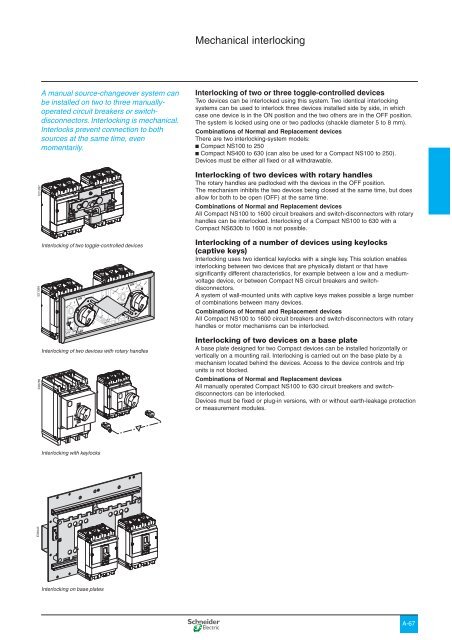
A manual source-changeover system can<br />
be installed on two to three manuallyoperated<br />
circuit breakers or switchdisconnectors.<br />
Interlocking is mechanical.<br />
Interlocks prevent connection to both<br />
sources at the same time, even<br />
momentarily.<br />
Interlocking of two toggle-controlled devices<br />
I<br />
ON<br />
ON<br />
ON<br />
I<br />
I<br />
O<br />
OFF<br />
tripped tripped<br />
reset<br />
reset<br />
O<br />
OFF<br />
Interlocking of two devices with rotary handles<br />
ON<br />
I<br />
reset<br />
I<br />
O<br />
O<br />
OFF<br />
ON<br />
O<br />
OFF<br />
OFF<br />
Interlocking of two or three toggle-controlled devices<br />
Two devices can be interlocked using this system. Two identical <strong>interlocking</strong><br />
systems can be used to interlock three devices installed side by side, in which<br />
case one device is in the ON position and the two others are in the OFF position.<br />
The system is locked using one or two padlocks (shackle diameter 5 to 8 mm).<br />
Combinations of Normal and Replacement devices<br />
There are two <strong>interlocking</strong>-system models:<br />
b Compact NS100 to 250<br />
b Compact NS400 to 630 (can also be used for a Compact NS100 to 250).<br />
Devices must be either all fixed or all withdrawable.<br />
Interlocking of two devices with rotary handles<br />
The rotary handles are padlocked with the devices in the OFF position.<br />
The mechanism inhibits the two devices being closed at the same time, but does<br />
allow for both to be open (OFF) at the same time.<br />
Combinations of Normal and Replacement devices<br />
All Compact NS100 to 1600 circuit breakers and switch-disconnectors with rotary<br />
handles can be interlocked. Interlocking of a Compact NS100 to 630 with a<br />
Compact NS630b to 1600 is not possible.<br />
Interlocking of a number of devices using keylocks<br />
(captive keys)<br />
Interlocking uses two identical keylocks with a single key. This solution enables<br />
<strong>interlocking</strong> between two devices that are physically distant or that have<br />
significantly different characteristics, for example between a low and a mediumvoltage<br />
device, or between Compact NS circuit breakers and switchdisconnectors.<br />
A system of wall-mounted units with captive keys makes possible a large number<br />
of combinations between many devices.<br />
Combinations of Normal and Replacement devices<br />
All Compact NS100 to 1600 circuit breakers and switch-disconnectors with rotary<br />
handles or motor mechanisms can be interlocked.<br />
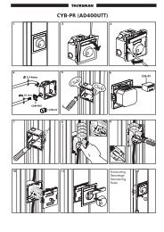
Interlocking of two devices on a base plate<br />
A base plate designed for two Compact devices can be installed horizontally or<br />
vertically on a mounting rail. Interlocking is carried out on the base plate by a<br />
mechanism located behind the devices. Access to the device controls and trip<br />
units is not blocked.<br />
Combinations of Normal and Replacement devices<br />
All manually operated Compact NS100 to 630 circuit breakers and switchdisconnectors<br />
can be interlocked.<br />
Devices must be fixed or plug-in versions, with or without earth-leakage protection<br />
or measurement modules.<br />
O<br />
OFF<br />
Interlocking with keylocks<br />
E33943<br />
Interlocking on base plates<br />
A-67
Functions and<br />
characteristics<br />
Source-changeover systems<br />
<strong>Electric</strong>al <strong>interlocking</strong><br />
<strong>Electric</strong>al <strong>interlocking</strong> is used with the<br />
mechanical <strong>interlocking</strong> system. It<br />
electrically interlocks the two circuit<br />
breakers and implements the time delays<br />
required for proper operation of the system.<br />
An automatic controller may be added to<br />
take into account information from the<br />
distribution system.<br />
<strong>Electric</strong>al <strong>interlocking</strong> is carried out by an electrical control device.<br />
For Compact NS up to 630 A, electrical <strong>interlocking</strong> is implemented by the IVE unit<br />
integrating control circuits and an external terminal block. The integrated control<br />
circuits implement the time delays required for correct source transfer.<br />
For Compact NS630b to 1600, this function can be implemented in one of two<br />
ways:<br />
b using the IVE unit<br />
b by an electrician based on the diagrams presented in the “<strong>Electric</strong>al diagrams”<br />
part of this catalogue.<br />
Characteristics of the IVE unit<br />
b external connection terminal block:<br />
v inputs: circuit breaker control signals<br />
v outputs: status of the SDE contacts on the “Normal” and “Replacement” source<br />
circuit breakers<br />
b 2 connectors for the two “Normal” and “Replacement” source circuit breakers:<br />
v inputs:<br />
- status of the OF contacts on each circuit breaker (ON or OFF)<br />
- status of the SDE contacts on the “Normal” and “Replacement” source circuit<br />
breakers<br />
v outputs: power supply for operating mechanisms<br />
b control voltage:<br />
v 24 to 250 V DC<br />
v 48 to 415 V 50/60 Hz - 440 V 60 Hz.<br />
The IVE unit control voltage must be same as that of the circuit breaker operating<br />
mechanisms.<br />
DB101573<br />
IVE unit.<br />
Necessary equipment<br />
For Compact NS100 to 630, each circuit breaker must be equipped with:<br />
b a motor mechanism<br />
b an OF contact<br />
b an SDE contact.<br />
The components are supplied ready for assembly and the circuit breakers<br />
prewired. The prewiring must not be modified.<br />
For Compact NS630b to 1600, each circuit breaker must be equipped with:<br />
b a motor mechanism<br />
b an available OF contact<br />
b a CE connected-position contact (carriage switch) on withdrawable circuit<br />
breakers<br />
b an SDE contact.<br />
A-68
Standard configurations<br />
DB110903<br />
Compact NS<br />
Types of mechanical <strong>interlocking</strong> Possible combinations Typical electrical diagrams Diagram no.<br />
2 devices<br />
QN QR Compact NS100 to 630:<br />
0 0 b electrical <strong>interlocking</strong> without emergency<br />
1 0 power off (EPO) auxiliaries: 51201177<br />
0 1 v with EPO by MN 51201178<br />
v with EPO by MX 51201179<br />
Compact NS630b to 1600:<br />
b electrical <strong>interlocking</strong> with lockout after fault:<br />
v permanent replacement source (without IVE) 51201180<br />
v with EPO by MX (without IVE) 51201181<br />
v with EPO by MN (without IVE) 51201182<br />
v permanent replacement source (with IVE) 51201183<br />
v with EPO by MX (with IVE) 51201184<br />
v with EPO by MN (with IVE) 51201185<br />
b automatic control without lockout after fault:<br />
v permanent replacement source (without IVE) 51201186<br />
v engine generator set (without IVE) 51201187<br />
A-69
push O F<br />
I<br />
push O F<br />
I<br />
push ON<br />
push ON<br />
O O F<br />
O O F<br />
discharged<br />
discharged<br />
0 1 2 5 3<br />
0 1 2 5 3<br />
push O F<br />
I<br />
push ON<br />
push O F<br />
I<br />
push ON<br />
O O F<br />
discharged<br />
O O F<br />
discharged<br />
0 1 2 5 3<br />
0 1 2 5 3<br />
Test<br />
Test<br />
stop<br />
N<br />
stop<br />
UN<br />
ON / I<br />
fault<br />
UN<br />
ON / I<br />
fault<br />
R<br />
R<br />
UR<br />
ON / I<br />
fault<br />
test<br />
R<br />
UR<br />
ON / I<br />
fault<br />
auto<br />
test<br />
0,5s<br />
0,5s<br />
R<br />
R<br />
Functions and<br />
characteristics<br />
Source-changeover systems<br />
Remote-operated systems<br />
PB100930-67<br />
Source-changeover system without a controller<br />
In this case, the automatic-control system to initiate changeovers between the<br />
Normal and Replacement sources under predefined conditions must be provided<br />
by the installation designer.<br />
Remote-operated source-changeover system<br />
053060<br />
053058<br />
Auxiliary control plate Controller<br />
E79368<br />
E79369<br />
O<br />
O<br />
Compact NS630b to 1600<br />
Interlocking by rods<br />
Interlocking by cables<br />
O<br />
O<br />
E32701 E32700<br />
E32699<br />
3<br />
1<br />
QN<br />
Source-changeover system with a controller<br />
In this case, changeovers between the Normal and Replacement sources under<br />
predefined conditions are initiated by a Merlin Gerin controller.<br />
5<br />
0 . OFF<br />
0 . OFF<br />
MERLIN GERIN<br />
N N<br />
manu<br />
OFF / O<br />
MERLIN GERIN<br />
OFF / O<br />
N N<br />
manu<br />
OFF / O<br />
N R<br />
OFF / O<br />
UN = O<br />
UN = 1<br />
UN = O<br />
UN = 1<br />
STOP generator<br />
B U S<br />
6<br />
Coupling accessory<br />
This accessory may be used with the source-changeover system (with or without<br />
a controller) to facilitate connections.<br />
4<br />
QR<br />
2<br />
7<br />
A remote-operated source-changeover system is made up of:<br />
1 circuit breaker QN equipped with a motor mechanism and auxiliary contacts, connected to<br />
the Normal source<br />
2 circuit breaker QR equipped with a motor mechanism and auxiliary contacts, connected to<br />
the Replacement source<br />
3 mounting base plate with mechanical <strong>interlocking</strong> (NS100 to 630) or an <strong>interlocking</strong> system<br />
using rods or cables (NS630b to 1600)<br />
4 electrical <strong>interlocking</strong> unit. IVE for NS100 to 630 or an electrical system provided by the<br />
installer for NS630b to 1600. <strong>Electric</strong>al <strong>interlocking</strong> system example: part no. 51156903 in the<br />
source-changeover system catalogue.<br />
Switching between sources can be automated by adding:<br />
5 ACP auxiliary control plate<br />
6 BA or UA controller, or an electrical system provided by the installer for NS630b to 1600.<br />
<strong>Electric</strong>al system example: part no. 51156904 and 51156904 in the sourcechangeover<br />
system catalogue.<br />
Accessory:<br />
7 coupling accessory (downstream connection) for NS100 to 630.<br />
A-70
Associated controllers<br />
PB100855<br />
PB100856<br />
By combining a remote-operated sourcechangeover<br />
system with an integrated BA<br />
or UA automatic controller, it is possible to<br />
automatically control source transfer<br />
according to user-selected sequences.<br />
These controllers can be used on sourcechangeover<br />
systems comprising 2 circuit<br />
breakers.<br />
For source-changeover systems comprising<br />
3 circuit breakers, the automatic control<br />
diagram must be prepared by the installer<br />
as a complement to to diagrams provided in<br />
the “electrical diagrams” section of this<br />
catalogue.<br />
BA controller.<br />
UA controller<br />
Controller BA UA<br />
4-position switch<br />
Compatible circuit breaker<br />
All Compact NS circuit breaker<br />
Automatic operation b b<br />
Forced operation on "Normal" source b b<br />
Forced operation on "Replacement" source b b<br />
Stop (both Normal and Replacement sources OFF) b b<br />
Automatic operation<br />
Monitoring of the "Normal" source and automatic transfer b b<br />
Generator set startup control<br />
b<br />
Delayed shutdown (adjustable) of engine generator set<br />
b<br />
Load shedding and reconnection of non-priority circuits b<br />
Transfer to the “Replacement” source if one of the phases b<br />
of the “Normal” phase is absent<br />
Test<br />
By opening the P25M circuit breaker supplying the controller<br />
By pressing the test button on the front of the controller<br />
Indications<br />
Circuit-breaker status indication on the front of the controller: b b<br />
on, off, fault trip<br />
Automatic mode indication contact b b<br />
Other functions<br />
Selection of type of "Normal" source<br />
b<br />
(single-phase or three-phase) (1)<br />
Voluntary transfer to "Replacement" source b b<br />
(e.g. energy-management commands)<br />
During peak-tariff periods (energy-management commands) b<br />
forced operation on "Normal" source if "Replacement" source<br />
not operational<br />
Additional control contact (not in controller). b b<br />
Transfer to "Replacement" source only if contact closed<br />
(e.g. used to test the frequency of UR)<br />
Setting of maximum startup time for the replacement source b<br />
Options<br />
Communication option<br />
Power supply<br />
Control voltages (2) 110 V b b<br />
220 to 240 V 50/60 Hz b b<br />
380 to 415 V 50/60 Hz b b<br />
440 V 60 Hz b b<br />
Operating thresholds<br />
Undervoltage 0.35 Un y voltage y 0.7 Un b b<br />
Phase failure 0.5 Un y voltage y 0.7 Un b<br />
Voltage presence voltage u 0.85 Un b b<br />
IP degree of protection (EN 60529) and IK degree of protection against<br />
external mechanical impacts (EN 50102)<br />
Front IP40 b b<br />
Side IP30 b b<br />
Connectors IP20 b b<br />
Front IK07 b b<br />
Characteristics of output contacts (dry, volt-free contacts)<br />
Rated thermal current (A) 8<br />
Minimum load<br />
10 mA at 12 V<br />
Output contacts:<br />
Position of the Auto/Stop switch b b<br />
Load shedding and reconnection order<br />
b<br />
Generator set start order<br />
b<br />
AC<br />
DC<br />
Utilisation category (IEC 60947-5-1)<br />
AC12 AC13 AC14 AC15 DC12 DC13<br />
Operational current (A) 24 V 8 7 5 6 8 2<br />
48 V 8 7 5 5 2 -<br />
110 V 8 6 4 4 0.6 -<br />
220/240 V 8 6 4 3 - -<br />
250 V - - - - 0.4 -<br />
380/415 V 5 - - - - -<br />
440 V 4 - - - - -<br />
660/690 V - - - - - -<br />
(1) For example, 220 V single-phase or 220 V three-phase.<br />
(2) The controller is powered by the ACP auxiliaries control plate. The same voltage must be<br />
used for the ACP plate, the IVE unit and the circuit-breaker operating mechanisms. If this<br />
voltage is the same as the source voltage, then the “Normal” and “Replacement” sources can be<br />
used directly for the power supply. If not, an isolation transformer must be used.<br />
b<br />
b<br />
b<br />
A-71
Functions and<br />
characteristics<br />
Communication<br />
Compact NS100 to 630<br />
E91685-54 E90463-25<br />
062052-28<br />
PB101038-26<br />
053172-25<br />
Communication with the circuit breaker or<br />
switch-disconnector is possible using a<br />
number of hardware solutions:<br />
b Advantys OTB Modbus interface module<br />
with built-in inputs/outputs<br />
b Power Meter units (PM700, PM800)<br />
b Micro Power Server MPS100 TCP IP/<br />
Modbus gateway with six digital alarm<br />
inputs.<br />
These solutions are compatible with<br />
existing installations equipped with<br />
communicating contacts.<br />
The Compact NS range can take<br />
advantage of the features of the MPS100,<br />
including automatic notification of alarms<br />
via e-mail and SMS messages.<br />
Advantys OTB Modbus.<br />
Power Meter.<br />
Micro Power Server MPS100.<br />
Compact NS equipped with<br />
communicating auxiliary<br />
contacts and motormechanism<br />
module.<br />
054481-22<br />
Withdrawable Compact NS<br />
on its chassis equipped with<br />
communicating auxiliary<br />
contacts.<br />
In addition to existing communication possibilities, new communication solutions<br />
are available for the range:<br />
b Advantys OTB Modbus interface module with 12 inputs/8 outputs built in and<br />
expandable by adding optional modules from the Twido range<br />
b Power Meter units (PM700, PM800) which can be used to set up four levels of<br />
functional units:<br />
v local display of currents, voltages, power, power factors, energy, total harmonic<br />
distortion (instantaneous and maximum THD values). The Power Meter units must<br />
be used in conjunction with a TCU measurement module,<br />
v remote display of all the above values via a local network or the internet via a<br />
Modbus/TCP IP gateway (type MPS100, EGX200, etc.). The Power Meter units<br />
must be equipped with a Modbus interface,<br />
v status indications. The Power Meter units must be equipped with IO22 alarm<br />
input/output module and the circuit breaker must be equipped with OF (on/off) and<br />
SDE (fault-trip indication) auxiliary contacts,<br />
v remote opening and closing. A motor-mechanism module must be added to the<br />
circuit breaker equipped for status indications<br />
b MPS100 TCP IP/Modbus gateway with six digital inputs to connect OF and SDE<br />
auxiliary contacts (see automatic notification on page A-81).<br />
The existing solutions remain available:<br />
b communicating auxiliaries<br />
They replace the standard auxiliaries and connect directly to the Digipact bus.<br />
Three equipment levels:<br />
v communicating auxiliary contacts, comprising:<br />
- OF (on/off), SD (trip indication) and SDE (fault-trip indication) contacts<br />
- electronic module<br />
- prefabricated wiring.<br />
v communicating auxiliary contacts and motor-mechanism module, comprising:<br />
- OF (on/off), SD (trip indication) and SDE (fault-trip indication) contacts<br />
- MCH motor-mechanism module (220 V AC) (1)<br />
- electronic module<br />
- prefabricated wiring.<br />
v communicating carriage switches for the chassis, comprising:<br />
- CE / CD (connected/disconnected position) contacts<br />
- electronic module<br />
- wiring connector<br />
b SC150 interface<br />
Using the SC150 interface, it is possible to integrate a device equipped with noncommunicating<br />
auxiliaries into a supervison system.<br />
The SC150 interface is used to connect:<br />
v the auxiliary contacts on the circuit breaker (OF, SD, SDE, SDV, CD, CE)<br />
v the remote-operation system (on, off, reset)<br />
v the communication output for the STR53UE and STR43ME electronic trip units<br />
equipped with the COM option.<br />
Software<br />
To make use of the information provided by the communicating devices, it is<br />
necessary to use software incorporating a Modbus driver. <strong>Schneider</strong> <strong>Electric</strong> offers<br />
two solutions: the RCU utility and SMS software.<br />
RCU utility<br />
This is a set of Modbus drivers that, in conjunction with a PC, can be used to:<br />
b view device status (on/off and fault trip),<br />
b view variables: currents, voltages, power, power factors, energy, total harmonic<br />
distortion (instantaneous and maximum THD values),<br />
b remotely open and close the device.<br />
SMS (System Management Software)<br />
SMS is power-management software to control and monitor LV and MV electrical<br />
installations.<br />
The SMS family includes a number of products offering different features for all<br />
types of applications.<br />
SMS can communicate with all intelligent devices in the electrical installation<br />
including:<br />
b Power Meter and Circuit Monitor products<br />
b LV circuit breakers and switch-disconnectors<br />
b Sepam units.<br />
054516-10<br />
SC150 indication and control<br />
interface.<br />
(1) For voltages other than 220 V AC, use a standard motor-mechanism module (noncommunicating)<br />
together with an SC150 indication and control interface.<br />
A-72
Overview of functions<br />
DB112381<br />
: wiring<br />
: communication bus<br />
: Modbus bus<br />
: Ethernet<br />
Compact equipped with:<br />
Advantys OTB PM700/800 Communicating SC150<br />
Modbus + interfaces auxiliaries<br />
Device identification<br />
Address b b b b<br />
Indication of status conditions<br />
OF (on/off) b b b b<br />
SD (trip indication) b - b b<br />
SDE (fault-trip indication) b b b b<br />
CE/CD (connected/disconnected position) b - b b<br />
Controls<br />
ON/OFF - b b b<br />
LED reset - - b b<br />
Protection settings<br />
Reading of the protection settings - - - b<br />
Operating and maintenance aids<br />
Measurements Currents - b - b<br />
Voltages, power, power factors, - b - -<br />
energy, THD - b - -<br />
Fault readings Type of fault - - - b<br />
Indications Operation counter - - - b<br />
A-73
CT<br />
CD<br />
CE<br />
CT<br />
CD<br />
CE<br />
Functions and<br />
characteristics<br />
Communication<br />
Compact NS630b to 1600<br />
COM option in Compact<br />
056431<br />
056401<br />
The COM option is required for integration<br />
of the circuit breaker or switch-disconnector<br />
in a supervision system.<br />
Compact uses the Digipact or Modbus<br />
communications protocol for full<br />
compatibility with the SMS PowerLogic<br />
electrical-installation management systems.<br />
An external gateway is available for<br />
communication on other networks:<br />
b Profibus<br />
b Ethernet…<br />
Digipact "device"<br />
communication module.<br />
Digipact "chassis"<br />
communication module<br />
DB105192<br />
For fixed circuit breakers, the COM option is made up of:<br />
b a "device" communication module, installed behind the Micrologic control unit<br />
and supplied with its set of sensors (OF, SD, SDE micro-contacts for manually<br />
operated devices; OF, SDE micro-contacts for electrically operated devices) and<br />
its kit for connection to a communicating motor-mechanism module.<br />
For withdrawable circuit breakers, the COM option is made up of:<br />
b a "device" communication module, installed behind the Micrologic control unit<br />
and supplied with its set of sensors (OF, SD, SDE micro-contacts for manually<br />
operated devices; OF, SDE micro-contacts for electrically operated devices) and<br />
its kit for connection to a communicating motor-mechanism module<br />
b a "chassis" communication module supplied separately with its set of sensors<br />
(CE, CD and CT contacts).<br />
Status indication by the COM option is independent of the circuit breaker<br />
indication contacts. These contacts remain available for conventional uses.<br />
Digipact or Modbus "device" communication module<br />
This module is independent of the control unit. It receives and transmits<br />
information on the communication network. An infra-red link transmits data<br />
between the control unit and the communication module. Consumption:<br />
30 mA, 24 V.<br />
Digipact or Modbus "chassis" communication module<br />
This module is independent of the control unit. The Modbus "chassis"<br />
communication module makes it possible to address the chassis and to maintain<br />
the address when the circuit breaker is in the disconnected position.<br />
Consumption: 30 mA, 24 V.<br />
Communicating motor-mechanism module<br />
A bus link is used to transmit remote ON/OFF orders to the circuit breaker.<br />
A communicating motor-mechanism module must be used.<br />
The remote-tripping function (MX or MN) is independent of the communication<br />
option. It therefore has no connectors for the "device" communication module.<br />
Communication<br />
bus<br />
Communication<br />
bus<br />
OF<br />
SD<br />
SDE<br />
3<br />
OF<br />
SDE<br />
3<br />
E45183 056431<br />
Modbus "device"<br />
communication module<br />
Modbus "chassis"<br />
communication module<br />
1<br />
1<br />
Manually operated<br />
fixed device<br />
Communication<br />
bus<br />
CCM modbus<br />
CD<br />
+ +<br />
+<br />
CT<br />
CE<br />
OF<br />
SD<br />
SDE<br />
I on<br />
tripped<br />
reset<br />
0 OFF<br />
2<br />
4<br />
3<br />
1<br />
Communication<br />
bus<br />
1<br />
<strong>Electric</strong>ally operated<br />
fixed device<br />
CCM modbus<br />
CD<br />
+ +<br />
+<br />
CE<br />
CT<br />
OF<br />
SDE<br />
5<br />
2<br />
4<br />
3<br />
5<br />
Manually operated<br />
withdrawable device<br />
<strong>Electric</strong>ally operated<br />
withdrawable device<br />
1 "device" communication module<br />
2 "chassis" communication module<br />
3 OF, SD, SDE "device" sensors<br />
4 CE, CD and CT "chassis" sensors<br />
5 communicating motor-mechanism module<br />
A-74
Overview of functions<br />
E47071<br />
POWERLOGIC System Manager Demo<br />
File Edit View Setup Control Display Reports Tools Window Help<br />
Sampling Mode : MANUAL 5 seconds<br />
Time<br />
Event<br />
Module<br />
Phase A-N Voltage - Harmonics Analysis<br />
Phase 1-N<br />
1,20<br />
Harmonics(RMS)<br />
% Fundamental<br />
Fundamental: H1: 118.09<br />
H2: 0.01<br />
1,00<br />
RMS:<br />
H3: 0.45<br />
H4: 0.03<br />
H5: 0.45<br />
RMS-H:<br />
H6: 0.04<br />
H7: 1.27<br />
0,80<br />
Peak:<br />
H8: 0.05<br />
H9: 0.42<br />
CF:<br />
H10: 0.01<br />
H11: 1.03<br />
THD:<br />
H12: 0.07<br />
0,60<br />
OK<br />
0,40<br />
Compact circuit breakers and switch-disconnectors are compatible with the<br />
Digipact or Modbus COM option.<br />
The COM option may be used with all types of control units to:<br />
b identify the device<br />
b indicate status conditions<br />
b control the device.<br />
Depending on the different types of Micrologic (S, A, P) control units, the COM<br />
option also offers:<br />
b setting of the protections functions<br />
b analysis of the AC-power parameters for operating-assistance and maintenance<br />
purposes<br />
0,20<br />
Ready<br />
0,00<br />
H2 H3 H4 H5 H6 H7 H8 H9 H10 H11 H12<br />
Harmonics<br />
ONLINE: DEMO No working system 9:30<br />
Switch-disconnector with Circuit breaker with<br />
communication bus communication bus<br />
Digipact Modbus Digipact Modbus<br />
Device identification<br />
Address b b S A P S A P<br />
Rating - - A P A P<br />
Type of device - - P<br />
Type of control unit - - A P A P<br />
Type of long-time rating plug - - A P A P<br />
Status indications<br />
ON/OFF OF b b S A P S A P<br />
SD (trip indication) b b S A P S A P<br />
SDE (fault-trip indication) - - S A P S A P<br />
CE/CD (connected/ b b S A P S A P<br />
disconnected position)<br />
Protections settings<br />
Reading of protections settings A P A P<br />
Writing of fine settings in the range P P<br />
imposed by the adjustment dials<br />
Reading/writing of alarms P P<br />
(load shedding and reconnect, etc.)<br />
Operating and maintenance aids<br />
Measurements<br />
current A P A P<br />
voltages, frequency, power, etc. P P<br />
programming of demand metering<br />
P<br />
Fault readings<br />
type of fault A P<br />
interrupted current<br />
P<br />
Histories and logs<br />
trip history<br />
P<br />
alarm history<br />
P<br />
event logs<br />
P<br />
Indicators<br />
counter operation A P A P<br />
Maintenance register<br />
P<br />
Note:<br />
S = Micrologic 2.0 and 5.0<br />
A = Micrologic with ammeter<br />
P = Micrologic "Power"<br />
See the description of the Micrologic control units for further details on protection.<br />
A-75
pulsar SV<br />
OK<br />
e ror<br />
N°1 N°1<br />
BBus<br />
com<br />
24V<br />
com<br />
e ror<br />
JBus<br />
Functions and<br />
characteristics<br />
Communication<br />
Compact NS630b to 1600 (cont.)<br />
Compact in a communication network<br />
E94525<br />
Software<br />
Communication<br />
interface<br />
RS 232C, Ethernet<br />
RS 485<br />
Communication<br />
bus<br />
MERLIN GERIN<br />
1 3<br />
Data concentrator<br />
DC150<br />
Device<br />
Digipact Bus<br />
Modbus Bus<br />
Compact<br />
Compact<br />
Devices<br />
Circuit breakers equipped with Micrologic control units may be connected to either<br />
a Digipact or Modbus communication bus. The information made available<br />
depends on the type of Micrologic control unit (A, P) and on the type of<br />
communication bus (Digipact or Modbus).<br />
Switch-disconnectors can be connected to the Digipact or Modbus communication<br />
bus. The information made available is the status of the switch-disconnector.<br />
Communication bus<br />
Digipact bus<br />
The Digipact bus is the internal bus of the low-voltage switchboard in which the<br />
Digipact communicating devices are installed (Compact with Digipact COM,<br />
PM150, SC150, UA150, etc.). This bus must be equipped with a DC150 data<br />
concentrator (see the Powerlogic System catalogue).<br />
Addresses<br />
Addressing is carried out by the DC150 data concentrator.<br />
Number of devices<br />
The maximum number of devices that may be connected to the Digipact bus is<br />
calculated in terms of “communication points”. These points correspond to the<br />
amount of traffic the bus can handle. The total number of points for the various<br />
devices connected to a single bus must not exceed 100.<br />
If the required devices represent more than 100 points, add a second Digipact<br />
internal bus.<br />
Communicating device Number of points<br />
DC150 data concentrator 4<br />
Micrologic + Digipact COM 4<br />
PM150 4<br />
SC150 4<br />
UA150 4<br />
Length of bus<br />
The maximum recommended length for the Digipact internal bus is 200 meters.<br />
Bus power source<br />
Power is supplied by the DC150 data concentrator (24 V).<br />
A-76
Modbus bus<br />
The Modbus RS 485 (RTU protocol) system is an open bus on which<br />
communicating Modbus devices (Compact with Modbus COM, Power Meter<br />
PM700, PM800, Sepam, Vigilohm, etc.) are installed. All types of PLCs and<br />
microcomputers may be connected to the bus.<br />
Addresses<br />
The Modbus parameters (address, baud rate, parity) are entered using the keypad<br />
on the Micrologic A, P. For a switch-disconnector, it is necessary to use the RSU<br />
(Remote Setting Utility) Micrologic utility.<br />
The software layer of the Modbus protocol can manage up to 255 addresses<br />
(1 to 255).<br />
The “device” communication module comprises three addresses linked to:<br />
b circuit-breaker manager<br />
b measurement manager<br />
b protection manager.<br />
The “chassis” communication module comprises one address linked to:<br />
b the chassis manager.<br />
The division of the system into four managers secures data exchange with the<br />
supervision system and the circuit-breaker actuators.<br />
The manager addresses are automatically derived from the circuit-breaker<br />
address @xx entered via the Micrologic control unit (the default address is 47).<br />
logic addresses<br />
@xx Circuit-breaker manager (1 to 47)<br />
@xx + 50 Chassis manager (51 to 97)<br />
@xx + 200 Measurement manager (201 to 247)<br />
@xx + 100 Protection manager (101 to 147)<br />
Number of devices<br />
The maximum number of devices that may be connected to the Modbus bus<br />
depends on the type of device (Compact with Modbus COM, PM700, PM800,<br />
Sepam, Vigilohm, etc.), the baud rate (19200 is recommended), the volume of<br />
data exchanged and the desired response time. The RS 485 physical layer offers<br />
up to 32 connection points on the bus (1 master, 31 slaves).<br />
A fixed device requires only one connection point (communication module on the<br />
device).<br />
A drawout device uses two connection points (communication modules on the<br />
device and on the chassis).<br />
The number must never exceed 31 fixed devices or 15 drawout devices.<br />
Length of bus<br />
The maximum recommended length for the Modbus bus is 1200 meters.<br />
Bus power source<br />
A 24 V DC power supply is required (less than 20 % ripple, insulation class II).<br />
Communication interface<br />
The Modbus bus may be connected to the central processing device in any of<br />
three manners:<br />
b direct link to a PLC. The communication interface is not required if the PLC is<br />
equipped with a Modbus port;<br />
b direct link to a computer. The Modbus (RS 485) / Serial port (RS 232)<br />
communication interface is required;<br />
b connection to a TCP/IP (Ethernet) network. The Modbus (RS 485) / TCP/IP<br />
(Ethernet) communication interface is required.<br />
Software<br />
To make use of the information provided by the communicating devices, software<br />
with a Modbus driver must be used.<br />
Micrologic utilities<br />
This is a set of Modbus drivers that may be used with a PC to:<br />
b display the variables (I, U, P, E, etc.) with the RDU (Remote Display Utility)<br />
b read/write the settings with the RSU (Remote Setting Utility)<br />
b remotely control (ON / OFF) the device with the RCU (Remote Control Utility).<br />
These utilities are available on request.<br />
System Manager Software (SMS)<br />
SMS is a power management software for the control and monitoring of LV and MV<br />
electrical installations.<br />
The SMS family includes a number of products for all types of applications, from<br />
standalone systems to networked power management of multiple buildings.<br />
SMS can communicate with all intelligent devices of the electrical installation<br />
including:<br />
b Power Meter and Circuit Monitor products<br />
b LV circuit breakers and switch-disconnectors<br />
b Sepam units.<br />
A-77
Functions and<br />
characteristics<br />
Communication<br />
Compact NS1600b to 3200<br />
COM option in Compact<br />
The COM option is required for integration<br />
of the circuit breaker or switch-disconnector<br />
in a supervision system.<br />
Compact uses the Digipact or Modbus<br />
communications protocol for full<br />
compatibility with the SMS PowerLogic<br />
electrical-installation management systems.<br />
An external gateway is available for<br />
communication on other networks:<br />
b Profibus<br />
b Ethernet…<br />
E59438<br />
For fixed circuit breakers, the COM option is made up of a "device" communication<br />
module, installed behind the Micrologic control unit and supplied with its set of<br />
sensors (OF, SD, SDE micro-contacts).<br />
Status indication by the COM option is independent of the circuit breaker<br />
indication contacts. These contacts remain available for conventional uses.<br />
Digipact or Modbus "device" communication module<br />
This module is independent of the control unit. It receives and transmits<br />
information on the communication network. An infra-red link transmits data<br />
between the control unit and the communication module.<br />
Consumption: 30 mA, 24 V.<br />
Communication<br />
bus<br />
056431<br />
Digipact "device"<br />
communication module.<br />
OF<br />
SD<br />
SDE<br />
2<br />
1<br />
OFF OFF<br />
COM<br />
module<br />
056431<br />
Modbus "device"<br />
communication module<br />
1 "Device" communication module<br />
2 OF, SD, SDE "device" sensors<br />
A-78
Overview of functions<br />
E47071<br />
POWERLOGIC System Manager Demo<br />
File Edit View Setup Control Display Reports Tools Window Help<br />
Sampling Mode : MANUAL 5 seconds<br />
Time<br />
Event<br />
Module<br />
Phase A-N Voltage - Harmonics Analysis<br />
Phase 1-N<br />
1,20<br />
Harmonics(RMS)<br />
% Fundamental<br />
Fundamental: H1: 118.09<br />
H2: 0.01<br />
1,00<br />
RMS:<br />
H3: 0.45<br />
H4: 0.03<br />
H5: 0.45<br />
RMS-H:<br />
H6: 0.04<br />
H7: 1.27<br />
0,80<br />
Peak:<br />
H8: 0.05<br />
H9: 0.42<br />
CF:<br />
H10: 0.01<br />
H11: 1.03<br />
THD:<br />
H12: 0.07<br />
0,60<br />
OK<br />
0,40<br />
Compact circuit breakers and switch-disconnectors are compatible with the<br />
Digipact or Modbus COM option.<br />
The COM option may be used with all types of control units to:<br />
b identify the device<br />
b indicate status conditions<br />
b control the device.<br />
Depending on the different types of Micrologic (S, A) control units, the COM option<br />
also offers:<br />
b setting of the protections functions<br />
b analysis of the AC-power parameters for operating-assistance and maintenance<br />
purposes<br />
Ready<br />
0,20<br />
0,00<br />
H2 H3 H4 H5 H6 H7 H8 H9 H10 H11 H12<br />
Harmonics<br />
ONLINE: DEMO No working system 9:30<br />
Switch-disconnector with Circuit breaker with<br />
communication bus communication bus<br />
Digipact Modbus Digipact Modbus<br />
Device identification<br />
Address b b S A S A<br />
Rating - - A A<br />
Type of control unit - - A A<br />
Type of long-time rating plug - - A A<br />
Status indications<br />
ON/OFF OF b b S A S A<br />
SD (trip indication) b b S A S A<br />
SDE (fault-trip indication) - - S A S A<br />
Protections settings<br />
Reading of protections settings A A<br />
Operating and maintenance aids<br />
Measurements<br />
current A A<br />
Fault readings<br />
type of fault<br />
A<br />
Indicator<br />
counter operation A A<br />
Note:<br />
S = Micrologic 2.0 and 5.0<br />
A = Micrologic with ammeter<br />
See the description of the Micrologic control units for further details on protection.<br />
A-79
Functions and<br />
characteristics<br />
Communication<br />
Compact and the MPS100<br />
Micro Power Server<br />
E90463<br />
E91685-60<br />
DB100435 056993<br />
The MPS100 Micro Power Server:<br />
b notifies maintenance staff when<br />
any preset alarm or trip is activated<br />
by the Micrologic trip unit, automatically<br />
sending an e-mail and/or SMS<br />
b data logs are periodically forwarded<br />
by e-mail<br />
b the e-mails are sent via an Ethernet local<br />
area network (LAN) or remotely<br />
via modem.<br />
MPS100 Micro Power Server.<br />
Main LV switchboard.<br />
Micro Power Server makes data collection easy<br />
for monitoring Masterpact / Compact circuit breakers<br />
Now, more than ever, there is a need to monitor electrical distribution systems in<br />
industrial and large commercial applications. The key to managing all equipment,<br />
maximising efficiencies, reducing costs and increasing up time is having the right<br />
tools.<br />
Micro Power Server MPS100 is designed to withstand harsh electrical<br />
environments and provide a consistent flow of easy to interpret information.<br />
Micro Power Server is designed for unattended operation<br />
within the main LV switchboard<br />
The MPS100 is a self-contained facility information server that serves as a standalone<br />
device for power system monitoring.<br />
It is used to transfer power system information via a standard web browser over<br />
an Ethernet local area network (LAN) or via modem, making it possible to view<br />
power system information on a PC with an Ethernet connection.<br />
In either capacity, the Micro Power Server functions as a web server for Micrologic<br />
trip unit and Power Meter supervision, automatically notifying (e-mail<br />
and/or SMS) maintenance staff when any preset alarm or trip is activated in<br />
the Micrologic trip unit.<br />
Benefits<br />
b view your main LV switchboard without installing software on your local PC,<br />
eliminating the need for a dedicated PC with specific software<br />
b Micro Power Server allows centralised monitoring, so you no longer waste<br />
precious time walking around the facility to collect data<br />
b view your main LV switchboard via a modem connection (GSM or switched<br />
network), avoiding the need for a LAN<br />
b maintenance people are automatically notified at any time, wherever they are,<br />
so you do not have to stay in front of a monitor all day long<br />
b data logs can be periodically forwarded by sending e-mails to the relevant<br />
people (maintenance, accounting, application service provider) automatically<br />
b possibility to monitor/notify six external events (limit switches, auxiliary<br />
switches...)<br />
b back-up of Micrologic trip unit settings in the memory of the MPS100, so you<br />
know where to retrieve it when necessary.<br />
Monitoring of the main LV switchboard via Web pages<br />
embedded in the MPS100 and accessible via a standard Web<br />
browser.<br />
A-80
Typical architecture<br />
056993-34<br />
Automatic notification<br />
Modbus I/O MPS100<br />
+ -<br />
+ -<br />
+ -<br />
Modem<br />
GSM<br />
SMS<br />
ISP WEB<br />
Modem<br />
OF<br />
SDE<br />
e-mail<br />
Monitoring from office PC<br />
Modbus I/O MPS100<br />
Hub<br />
LAN<br />
LAN<br />
Monitoring from home PC<br />
Modbus I/O MPS100<br />
DB103808<br />
Modem<br />
GSM<br />
Modem<br />
It is possible to combine the different types of architecture.<br />
E89544-14<br />
E95405R<br />
Micrologic trip unit.<br />
PB100708<br />
Power Meter.<br />
Main switchboard at<br />
Plaza hotel.<br />
Air conditioning breaker<br />
tripped on ground fault<br />
Ig = 350 A.<br />
06:37 on 10/12/2002<br />
Supported Modbus devices<br />
b Micrologic trip units<br />
b Power Meters (PM700, PM800).<br />
Maximum recommended connected devices is 10.<br />
Features<br />
b access to the power system via a standard PC web browser<br />
b real-time data displayed with an intuitive and user friendly interface<br />
(dashboard)<br />
b Ethernet Modbus TCP/IP connectivity directly to the LAN or via modem (Point to<br />
Point Protocol services)<br />
b SMTP (Simple Mail Transfer Protocol) client (capacity to send e-mail)<br />
b local logging of data such as energy, power, current…<br />
b set-up and system configuration through MPS100 embedded HTML pages<br />
b user interface translatable in any language, factory settings in English and<br />
French<br />
b 6 inputs/2 outputs (no-volt contact)<br />
b DHCP (Dynamic Host Configuration Protocol) client.<br />
Technical characteristics<br />
Power supply<br />
24 V DC ±15 %, consumption = 250 mA<br />
Operating temperature 0 to +50 °C<br />
Rugged compact metal housing 35 x 218 x 115 mm (H x W x D)<br />
Additional information available at: http://194.2.245.4/mkt/microser.nsf<br />
User name: MPS, Password: MPS100<br />
Short Message Service (SMS).<br />
A-81
65<br />
25<br />
push<br />
to<br />
trip<br />
1<br />
1<br />
Functions and<br />
characteristics<br />
<strong>Electric</strong>al and mechanical<br />
accessories<br />
Compact NS80H-MA<br />
E58516<br />
Sealable terminal<br />
shield<br />
DIN-rail<br />
plate<br />
compact<br />
NS 80 H-MA<br />
Ui750V. Uimp 8kV.<br />
Ue (V) Icu (kA)<br />
220/240 100<br />
380/415 70<br />
440<br />
500/525<br />
660/690<br />
250<br />
cat A<br />
Ics = 100% Icu<br />
IEC 947.2<br />
10 6<br />
UTE VDE BS CEI UNE<br />
Auxiliary<br />
contact<br />
Direct rotary<br />
handle<br />
ON<br />
I<br />
push<br />
to<br />
trip<br />
O<br />
OFF<br />
2<br />
push<br />
to<br />
trip<br />
2<br />
ON<br />
I<br />
C1 C2<br />
MX/SHT<br />
220-240V/50-60Hz<br />
Voltage release<br />
tripped<br />
reset<br />
O<br />
OFF<br />
∅5 .8<br />
Sealable terminal<br />
shield<br />
Extended rotary<br />
handle<br />
Auxiliary<br />
contact<br />
A-82
440<br />
125<br />
25<br />
16<br />
10<br />
5<br />
440<br />
125<br />
25<br />
16<br />
10<br />
5<br />
Compact NSC100N, NSA160<br />
Front accessory for NSC100N (45 mm standard door cutout)<br />
E58517<br />
compact<br />
NSA 125E<br />
U 500V. Uimp 6kV.<br />
Ue (V) Icu (kA)<br />
220/240<br />
380/415<br />
Ics = 50% Icu<br />
IEC 947.2<br />
UTE VDE BS CEI UNE<br />
45 mm front<br />
E58518<br />
Sealable terminal<br />
shield<br />
compact<br />
NSA 125E<br />
U 500V. Uimp 6kV.<br />
Ue (V) Icu (kA)<br />
220/240<br />
380/415<br />
Auxiliary<br />
contact<br />
Ics = 50% Icu<br />
IEC 947.2<br />
UTE VDE BS CEI UNE<br />
ON<br />
I<br />
C1 C2<br />
MX/SHT<br />
220-240V/50-60Hz<br />
Voltage release<br />
tripped<br />
reset<br />
O<br />
OFF<br />
∅5 .8<br />
Extended rotary<br />
handle<br />
Sealable terminal<br />
shield<br />
A-83
push<br />
to<br />
trip<br />
Functions and<br />
characteristics<br />
<strong>Electric</strong>al and mechanical<br />
accessories<br />
Compact NS80H-MA, NSC100N and NSA160<br />
E59278<br />
Installation positions<br />
Installation<br />
Compact NS80H-MA and NSC100N circuit breakers may be mounted vertically,<br />
horizontally or flat on their back without any derating of characteristics. They are<br />
designed for easy installation in the various types of switchboards of each market<br />
and country.<br />
Mounting on a DIN rail is possible using a special adapter.<br />
The NSA160 circuit breaker may be mounted exclusively on a DIN rail.<br />
These three circuit breakers are available in the fixed, front-connection version.<br />
E43595<br />
E43596<br />
E43597<br />
O F F<br />
NS80H-MA and NSC100N:<br />
mounting on backplate or<br />
mounting plate.<br />
NS80H-MA and NSC100N:<br />
mounting on DIN rail<br />
(optional).<br />
NSA160: mounting on DIN<br />
rail (standard).<br />
Standard 45 mm front,<br />
optional on NSC100N,<br />
standard on NSA160.<br />
E54455<br />
Front connection of bare cables<br />
Compact NS80H-MA, NSC100N and NSA160 circuit breakers are equipped as<br />
standard with connectors for bare copper or<br />
aluminium cables from 1.5 to<br />
70 mm 2 .<br />
Distribution connector<br />
This connector screws directly to the standard<br />
connectors. It is used to connect up to three cables:<br />
b flexible cables from 1 to 10 mm 2<br />
b rigid cables from 1.5 to 16 mm 2<br />
b with crimped or self-crimping ferrules from 1.5 to<br />
4 mm 2 .<br />
E39432<br />
Distribution connector<br />
Insulation of live parts<br />
Terminal shields<br />
Insulating accessories used for protection against<br />
direct contact with power circuits (degree of protection<br />
IP40, IK07). They are supplied with sealing<br />
accessories.<br />
For voltages u 500 V, terminal shields are mandatory.<br />
E58553<br />
Terminal shields<br />
A-84
044314<br />
Indication contacts<br />
Common-point changeover contacts provide remote circuitbreaker<br />
status information. They can be used for indications,<br />
electrical locking, relaying, etc.<br />
Indication contacts<br />
A single type of contact, complying with the IEC 60947-5 international<br />
recommendation, provides different indication functions, depending on where it is<br />
inserted in the device.<br />
b OF (ON/OFF) - indicates the position of the circuit breaker contacts<br />
b SD (trip indication) - indicates that the circuit breaker has tripped due to:<br />
v an overload<br />
v a short-circuit<br />
v an earth-leakage fault (Compact NSC100N and NSA160)<br />
v operation of a voltage release.<br />
Returns to de-energised state when the circuit breaker is reset.<br />
b SDV (earth-leakage fault indication) - inserted in the Vigi module on Compact<br />
NSC100N and NSA160 devices, it indicates that the circuit breaker has tripped<br />
due to an earth fault. Returns to de-energised state when the circuit breaker is<br />
reset.<br />
All the above auxiliary contacts are also available in “low-level” versions capable of<br />
switching very low loads (e.g. for the control of PLCs or electronic circuits).<br />
Characteristics<br />
Contacts Standard Low level<br />
Rated thermal current (A) 6 5<br />
Minimum load 100 mA at 24 V 1 mA at 4 V<br />
Utilisation cat. (IEC 60947-5-1) AC12 AC15 DC12 DC14 AC12 AC15 DC12 DC14<br />
Operational 24 V 6 6 6 1 5 3 5 1<br />
current (A) 48 V 6 6 2.5 0.2 5 3 2.5 0.2<br />
110 V 6 5 0.6 0.05 5 2.5 0.6 0.05<br />
220/240 V 6 4 - - 5 2 - -<br />
250 V - - 0.3 0.03 5 - 0.3 0.03<br />
380/440 V 6 2 - - 5 1.5 - -<br />
480 V 6 1.5 - - 5 1 - -<br />
660/690 V 6 0.1 - - - - - -<br />
054550<br />
MX or MN voltage release<br />
Remote tripping<br />
MX or MN voltage releases are used to trip the circuit breaker.<br />
MN undervoltage release<br />
This release trips the circuit breaker when the control voltage drops below a<br />
tripping threshold:<br />
b tripping threshold between 0.35 and 0.7 times the rated voltage<br />
b circuit breaker closing is possible only if the voltage exceeds 0.85 times the<br />
rated voltage.<br />
Circuit breaker tripping by an MN release meets the requirements of standard<br />
IEC 60947-2.<br />
Time-delay unit for an MN release (Compact NS80H-MA)<br />
Eliminates nuisance tripping due to transient voltage dips lasting y 200 ms:<br />
It is used in conjunction with:<br />
b a 250 V DC MN release, control voltage 220/240 V AC<br />
b a 48 V DC MN release, control voltage 48 V AC.<br />
MX shunt release<br />
Trips the circuit breaker when the control voltage rises above 0.7 x Un.<br />
Control signals can be of the impulse type (u 20 ms) or maintained.<br />
Operation<br />
When the circuit breaker has been tripped by an MN or MX release, it must be<br />
reset locally.<br />
MN or MX tripping takes priority over manual closing.<br />
In the presence of a standing trip order, closing of the contacts, even temporary,<br />
is not possible.<br />
<strong>Mechanical</strong> characteristics<br />
b endurance is equal to 50 % of the mechanical endurance of the circuit breaker<br />
b the releases clip in behind the front cover<br />
b connection using wires up to 1.5 mm 2 to integrated terminal blocks.<br />
<strong>Electric</strong>al characteristics<br />
b consumption:<br />
v pick-up (MX): < 5 VA<br />
v seal-in (MN): < 5 VA<br />
b response time: < 50 ms.<br />
A-85
Functions and<br />
characteristics<br />
<strong>Electric</strong>al and mechanical<br />
accessories<br />
Compact NS80H-MA, NSC100N and NSA160<br />
(cont.)<br />
054558<br />
054563<br />
Compact NS80H-MA with a direct rotary handle<br />
Compact NS80H-MA with an extended rotary handle<br />
Rotary handles<br />
There are two types of rotary handle:<br />
b direct rotary handle<br />
b extended rotary handle.<br />
There are two models:<br />
b standard with a black handle<br />
b VDE with a red handle and yellow front for machine-tool control.<br />
Direct rotary handle (NS80H-MA and NSC100N)<br />
Degree of protection IP40, IK07.<br />
The direct rotary handle maintains:<br />
b visibility of and access to trip unit settings<br />
b suitability for isolation<br />
b indication of the three positions O (OFF), I (ON) and tripped<br />
b access to the “push to trip” button<br />
b circuit breaker locking capability in the OFF position by one to three padlocks,<br />
shackle diameter Ø 5 to 8 mm (not supplied).<br />
It replaces the circuit-breaker front cover.<br />
Accessories transform the standard direct rotary handle for the following<br />
situations:<br />
b motor control centre (MCC) switchboards:<br />
v door opening disabled when the circuit breaker is ON<br />
v circuit-breaker closing is disabled if the door is open<br />
b a higher degree of protection (IP43, IK07)<br />
b machine-tool control, complying with CNOMO E03.81.501, IP54, IK08.<br />
Extended rotary handle<br />
Degree of protection IP55, IK08.<br />
This handle makes it possible to operate circuit breakers installed at the back of<br />
switchboards, from the switchboard front.<br />
It maintains:<br />
b suitability for isolation<br />
b indication of the three positions O (OFF), I (ON) and tripped<br />
b access to trip unit settings, when the switchboard door is open<br />
b circuit breaker locking capability in the OFF position by one to three padlocks,<br />
shackle diameter 5 to 8 mm (not supplied).<br />
The door cannot be opened if the circuit breaker is ON or locked.<br />
The extended rotary handle is made up of:<br />
b a unit that replaces the front cover of the circuit breaker (secured by screws)<br />
b an assembly (handle and front plate) on the door that is always secured in the<br />
same position, whether the circuit breaker is installed vertically or horizontally<br />
b an extension shaft that must be adjusted to the distance (min/max distance<br />
between back of circuit breaker and door is 185/600 mm).<br />
A-86
Locking systems<br />
Locking in the OFF position guarantees isolation as per IEC 60947-2.<br />
Padlocking systems can receive up to three padlocks with shackle diameters<br />
ranging from 5 to 8 mm (padlocks not supplied).<br />
E58552<br />
Toggle locking using a removable device<br />
Outgoing-circuit identification<br />
Compact NS80H-MA and NSC100N devices come with clip-in labels for handwritten<br />
indications.<br />
It is also possible to use pre-printed Telemecanique labels<br />
(part number AB1-** (8 digits)).<br />
E18595<br />
D E P. P O M P<br />
DEP.<br />
P<br />
push<br />
to<br />
trip<br />
O<br />
Identification accessories<br />
A-87
220/<br />
240<br />
380/<br />
415<br />
440<br />
500/<br />
Ics=10<br />
ca<br />
UTE VDE<br />
U<br />
e<br />
3<br />
2<br />
1.5<br />
xIr<br />
Im<br />
4 5<br />
8<br />
10<br />
6<br />
0<br />
6<br />
1<br />
0<br />
7<br />
Ic<br />
u<br />
In=250A<br />
3<br />
2<br />
1.5<br />
xIr<br />
Ir<br />
Im<br />
4 5<br />
8<br />
10<br />
Im<br />
6<br />
Im<br />
Ir<br />
2<br />
3<br />
Im<br />
1<br />
.<br />
x 250A<br />
.<br />
I<br />
9<br />
p us<br />
8<br />
10 5<br />
7<br />
x 250A<br />
alarm<br />
90<br />
105 %Ir<br />
Im<br />
4 5<br />
8<br />
10<br />
xIr<br />
6<br />
.85 .9<br />
.8 .95<br />
.98<br />
.7<br />
.63 1<br />
xIn<br />
+ -<br />
3<br />
2<br />
1.5<br />
xIr<br />
alarm<br />
90<br />
105 %Ir<br />
6<br />
1<br />
I<br />
I<br />
test<br />
Im<br />
4 5<br />
8<br />
10<br />
6<br />
+ -<br />
alarm<br />
90<br />
3<br />
2<br />
1.5<br />
xIr<br />
4 5<br />
8<br />
10<br />
6<br />
test<br />
+ -<br />
test<br />
avant<br />
test<br />
diélec<br />
trique<br />
enlev<br />
0<br />
H<br />
1<br />
6<br />
3<br />
5<br />
3<br />
0<br />
0,<br />
1<br />
I∆<br />
v<br />
∆t<br />
2 4 6<br />
v<br />
N<br />
5<br />
20<br />
ect<br />
ava<br />
nt<br />
test<br />
diél<br />
-<br />
U<br />
20<br />
/24<br />
0<br />
380<br />
/41<br />
5<br />
ca<br />
Ics =<br />
IEC<br />
947-2<br />
com<br />
NS2<br />
Icu<br />
1<br />
5<br />
0<br />
1<br />
5<br />
0<br />
L L L<br />
20/6<br />
r<br />
U<br />
20<br />
/24<br />
0<br />
380<br />
/41<br />
5<br />
ca<br />
Ics =<br />
IEC<br />
947-2<br />
com<br />
NS2<br />
Icu<br />
1<br />
5<br />
0<br />
1<br />
5<br />
0<br />
r<br />
t<br />
r<br />
p<br />
∅<br />
∅<br />
U<br />
20<br />
/24<br />
0<br />
380<br />
/41<br />
5<br />
ca<br />
Ics =<br />
IEC<br />
947-2<br />
com<br />
NS2<br />
Icu<br />
1<br />
5<br />
0<br />
1<br />
5<br />
0<br />
p<br />
p<br />
∅<br />
1<br />
2<br />
Functions and<br />
characteristics<br />
<strong>Electric</strong>al and mechanical<br />
accessories<br />
Compact NS100 to 630 (fixed version)<br />
DB105106<br />
Rear insulating<br />
screens<br />
Sealable terminal<br />
shield<br />
Voltage-presence<br />
indicator<br />
Rear connectors<br />
Connectors<br />
One-piece<br />
spreader<br />
terminal extensions<br />
and spreaders<br />
Interphase barriers<br />
comp<br />
NB250NH<br />
Ui 750V.<br />
IEC947-2<br />
I T M<br />
Ui Uim<br />
O<br />
N<br />
p<br />
us O<br />
. O<br />
N<br />
2<br />
Ui Uim<br />
O<br />
N<br />
u<br />
s O<br />
Direct rotary<br />
handle<br />
Ui Uim<br />
m a<br />
O d<br />
Motor-mechanism<br />
module<br />
O<br />
I<br />
Auxiliary contact<br />
Voltage release<br />
O<br />
N<br />
O<br />
Extended rotary<br />
handle<br />
Ir STR 22 SE<br />
105 %Ir<br />
Ir 1.5<br />
STR 22 SE<br />
4<br />
8<br />
1<br />
0<br />
A<br />
Trip units<br />
STR 22 SE<br />
Ammeter module<br />
Current-transformer<br />
module<br />
Insulation-monitoring<br />
module<br />
Rear insulating<br />
screens<br />
Sealable terminal<br />
shield<br />
A-88
440<br />
250<br />
cat A<br />
Ue<br />
(V)<br />
Icu<br />
(kA)<br />
100<br />
70<br />
65<br />
50<br />
10<br />
85<br />
1<br />
.9<br />
x 250A<br />
.8<br />
push<br />
to<br />
trip<br />
Im<br />
9<br />
8<br />
10 5<br />
7<br />
x 250A<br />
6<br />
Ir<br />
Im<br />
250A/40°C<br />
Compact NS100 to 630<br />
(plug-in and withdrawable versions)<br />
DB105105<br />
Plug-in base<br />
sealable<br />
terminal shield<br />
Interphase barriers<br />
Crimp lugs<br />
Crimp lugs<br />
Connectors<br />
Terminal extensions<br />
and spreaders<br />
Terminal<br />
extensions<br />
and<br />
spreaders<br />
Connectors<br />
Plug-in base<br />
shield adapter<br />
Connected /<br />
disconnected<br />
contacts<br />
Plug-in base<br />
Manual auxiliary connector<br />
Sealable terminal<br />
shield<br />
Drawout<br />
control<br />
wires<br />
Chassis<br />
side plate<br />
Plug-in base<br />
shield adapter<br />
Control-wire<br />
connection plate<br />
Power<br />
connections<br />
Voltage-presence<br />
indicator<br />
Vigicompact<br />
power connections<br />
Interphase<br />
barriers<br />
compact<br />
NB250NH<br />
Ui 750V. Uimp 8kV.<br />
220/240<br />
380/415<br />
500/525<br />
660/690<br />
Ics=100% Icu<br />
IEC947-2<br />
UTE VDE BS CEI UNE NEMA<br />
125/160<br />
Ir TM 250 D<br />
Circuit-breaker<br />
side plate<br />
Plug-in base<br />
sealable<br />
terminal shield<br />
Circuit-breaker<br />
side plate<br />
Sealable terminal<br />
shield<br />
These withdrawable circuit breakers can be equipped with the same rotary<br />
handles, motor mechanisms and measurement and indication modules<br />
as the fixed versions.<br />
A-89
Functions and<br />
characteristics<br />
<strong>Electric</strong>al and mechanical<br />
accessories<br />
Compact NS100 to 630<br />
045345<br />
Installation<br />
Fixed circuit breakers<br />
Compact circuit breakers may be mounted vertically, horizontally or flat on their<br />
back without any derating of characteristics. They are designed for easy<br />
installation in the various types of switchboards of each market and country.<br />
Mounting on a backplate<br />
(solid or slotted)<br />
Mounting on rails<br />
Circuit breaker on a plug-in base<br />
041632<br />
E18850<br />
E58529<br />
E58530<br />
E58714<br />
Fixed Compact NS250H<br />
E59278<br />
Installation positions<br />
Mounting on DIN rail (with<br />
adapter)<br />
The plug-in configuration makes it possible<br />
to:<br />
b extract and/or rapidly replace the circuit<br />
breaker without having to touch<br />
connections<br />
b allow for the addition of future circuits<br />
at a later date.<br />
Mounting on a Prisma functional mounting plate.<br />
E21017<br />
E21018<br />
E21019<br />
E59279<br />
Compact NS250H on a plug-in base<br />
Installation positions<br />
Mounting on a backplate<br />
Mounting through a front<br />
panel<br />
Mounting on rails<br />
Protection against direct contacts with power circuits<br />
b circuit breaker plugged in = IP4<br />
b circuit breaker removed = IP2<br />
b circuit breaker removed, base equipped with shutters = IP4<br />
Parts of a plug-in configuration<br />
b Compact circuit breaker<br />
b set of power connectors added to the circuit breaker<br />
b plug-in base for mounting on a backplate or on rails<br />
b insulating screen, for use when the circuit breaker is installed on a backplate<br />
with front connections<br />
b safety trip, installed on the circuit breaker, that causes automatic tripping if the<br />
circuit breaker is ON, before engaging or withdrawing it. The safety trip does not<br />
prevent circuit breaker operation, even when it has been removed.<br />
b mandatory short terminal shields.<br />
Accessories<br />
Insulating accessories can be used to:<br />
b protect against direct contact<br />
b increase insulation between phases.<br />
A-90
041879<br />
b disconnected position - the power circuits<br />
are disconnected, but the circuit breaker is<br />
still on the chassis and may still be operated<br />
(ON, OFF, push-to-trip).<br />
b the circuit breaker may be locked using<br />
1 to 3 padlocks (shackle diameter 5 to<br />
8 mm), to prevent connection.<br />
b the auxiliaries can be tested (with manual<br />
auxiliary connector).<br />
E21282<br />
Circuit breaker on a withdrawable chassis<br />
Connected Disconnected Removed<br />
The chassis is made up of two side plates installed on the base and two other<br />
plates mounted on the circuit breaker.<br />
Accessories<br />
b auxiliary contacts for installation on the fixed part, indicating the “connected” and<br />
“disconnected” positions<br />
b toggle collar for circuit breakers with a toggle mounted through a front panel,<br />
intended to maintain the degree of protection whatever the position of the circuit<br />
breaker (supplied with a toggle extension)<br />
b keylock which, depending on the bolt fitted, can be used to:<br />
v prevent insertion for connection<br />
v lock the circuit breaker in the connected or disconnected positions.<br />
b telescopic shaft for extended rotary handles.<br />
Compact NS250H on a withdrawable chassis<br />
Front and rear connections<br />
Fixed, plug-in and withdrawable Compact devices may all be equipped with front<br />
and rear connections.<br />
Fixed device<br />
E58733<br />
E58716<br />
Front connection<br />
Rear connection<br />
Plug-in and withdrawable devices<br />
E58718<br />
E58717<br />
E58719<br />
E59279<br />
Installation positions<br />
Front connection Rear connection Rear connection through<br />
a backplate<br />
A-91
Functions and<br />
characteristics<br />
<strong>Electric</strong>al and mechanical<br />
accessories<br />
Compact NS100 to 630 (cont.)<br />
E54456<br />
E58531<br />
E58720<br />
E58532<br />
Connection of fixed devices<br />
Front connection of bars or cables<br />
with lugs<br />
The Compact NS100 to NS630 devices are equipped<br />
as standard with terminals comprising snap-in nuts<br />
with screws (M8 for NS100 to 250, M10 for NS400 to<br />
630) for direct connection to insulated bars or cables<br />
with lugs.<br />
Additional terminal extensions (right-angle, edgewise,<br />
spreaders) are available for all connection<br />
requirements. Spreaders (52.5 or 70 mm pitch) may<br />
be fitted on the Compact NS400 to 630.<br />
Lugs<br />
Lugs are different for copper and aluminium cables.<br />
They are supplied with interphase barriers and are<br />
compatible with the long terminal shields.<br />
b the small lugs for copper cables may be used for<br />
cables with the following cross-sectional areas:<br />
v 120, 150 or 185 mm 2 (NS100 to 250)<br />
v 240 or 300 mm 2 (NS400 to 630).<br />
Crimping by hexagonal barrels or punching.<br />
b the small lugs for aluminium cables may be used for<br />
cables with the following cross-sectional areas:<br />
v 150 or 185 mm 2 (NS100 to 250)<br />
v 240 or 300 mm 2 (NS400 to 630).<br />
Crimping by hexagonal barrels.<br />
Spreaders<br />
Spreaders increase the pitch of the terminals.<br />
They are not compatible with terminal shields on the<br />
Compact NS100 to 250.<br />
The one-piece spreader increases the pitch, thus<br />
making it possible to use the connection accessories<br />
of a larger device (e.g. a Compact NS100 to 250 can<br />
be fitted with the accessories of a Compact NS400 to<br />
630). The one-piece spreader also provides protection<br />
against direct contact (see page A-95).<br />
E58534<br />
E58535<br />
E58536<br />
E58537<br />
E58538<br />
Right-angle terminal<br />
extensions<br />
Straight terminal extensions<br />
for NS100 to 250<br />
Edgewise terminal<br />
extensions for NS400 to 630<br />
Small lug for copper cables<br />
Small lug for aluminium<br />
cables<br />
E58539<br />
Spreaders<br />
E58721<br />
E58533<br />
One-piece spreader<br />
A-92
E54457<br />
E58540<br />
E58722<br />
Front connection of bare cables<br />
Bare-cable connectors for Compact NS devices may<br />
be used for both copper and aluminium cables.<br />
1-cable connectors for Compact NS100 to 250<br />
The connectors snap directly on to the device<br />
terminals or clip onto right-angle and straight terminal<br />
extensions as well as spreaders.<br />
1-cable and 2-cable connectors for Compact<br />
NS400 to 630<br />
The connectors are screwed to device terminals or<br />
right-angle terminal extensions.<br />
Distribution connectors for Compact NS100 to 250<br />
These connectors are screwed directly to device<br />
terminals. Interphase barriers are supplied with<br />
distribution connectors, but may be replaced by long<br />
terminal shields. Each connector can receive six<br />
cables with cross-sectional areas ranging from 1.5 to<br />
35 mm 2 each.<br />
Polybloc distribution block for Compact NS100 to 630<br />
The Polybloc connects directly to the device terminals<br />
and is used to connect up to six or nine flexible or<br />
rigid cables with cross-sectional areas not exceeding<br />
10 mm 2 , to each pole. Connection is made to spring<br />
terminals without screws.<br />
E54472 E54471<br />
E54470 E54469 E54468<br />
1-cable connector<br />
for NS100 to 250<br />
1-cable connector<br />
for NS400 to 630<br />
2-cable connector<br />
for NS400 to 630<br />
Distribution connector<br />
for NS100 to 250<br />
Polybloc distribution block<br />
for NS100 to 250<br />
E54456<br />
E58723<br />
Rear connection<br />
Rear connections for bars or cables with lugs are<br />
available in two lengths. Bars may be positioned flat,<br />
on edge or at 45° angles depending on how the rear<br />
connections are positioned.<br />
The rear connections are simply fitted to the device<br />
connection terminals. All combinations of rear<br />
connection lengths and positions are possible on a<br />
given device. The device is mounted on a backplate.<br />
For the connection of cables without lugs, the 1-cable<br />
connectors for Compact NS100 to 250 may be simply<br />
clipped onto the rear connections.<br />
E58725 E58724<br />
Two lengths<br />
Four positions<br />
E58726<br />
Connection<br />
of bare cables<br />
to NS100 to 250.<br />
A-93
Functions and<br />
characteristics<br />
<strong>Electric</strong>al and mechanical<br />
accessories<br />
Compact NS100 to 630 (cont.)<br />
E54456<br />
Connection of plug-in devices<br />
Connection of bars or cables with lugs<br />
The plug-in base is equipped with terminals which, depending on their orientation,<br />
serve for front and rear connection. For rear connection of a base mounted on a<br />
backplate, the terminals must be replaced by insulated, long right-angle terminal<br />
extensions.<br />
For Compact NS630 devices, connection most often requires the 52.5 or 70 mm<br />
pitch spreaders.<br />
Connection accessories<br />
See the “Connection of fixed devices” section.<br />
Connection of bare cables<br />
All terminals may be equipped with bare-cable connectors. See the “Connection of<br />
fixed devices” section.<br />
DB105158<br />
E58729<br />
E58718<br />
E58717<br />
E58727<br />
Front connection<br />
Front connection with<br />
spreaders<br />
Rear connection<br />
E58719<br />
Rear connection of a base<br />
mounted on a backplate<br />
E54457<br />
Plug-in base for Compact<br />
NS100 to 250 equipped with<br />
1-cable connectors<br />
Plug-in base for Compact<br />
NS400 to 630 equipped with<br />
2-cable connectors<br />
A-94
056384<br />
One-piece spreader<br />
One-piece spreader<br />
Connection of large cables may require an increase in<br />
the distance between the device terminals. The onepiece<br />
spreader is an accessory that can also be fitted<br />
on Interpact INS switch-disconnectors. It offers the<br />
following features:<br />
b increases the pitch of the circuit-breaker terminals<br />
to correspond to that of the next largest frame size<br />
b compatible with all the connection accessories<br />
available for the next largest frame size (connectors,<br />
terminal extensions, etc.)<br />
b enhances insulation between phases in comparison<br />
with standard spreaders.<br />
NS100 to 250 NS400 to 630<br />
Pitch without 35 45<br />
spreaders (mm)<br />
Pitch with standard 45 52.5 or 70<br />
spreaders (mm)<br />
Pitch with one-piece 45 -<br />
spreader (mm)<br />
Mounting<br />
When equipped with a one-piece spreader, Compact<br />
NS circuit breakers may be installed either at the back<br />
of a switchboard or on the front panel with a raiser.<br />
b devices with different frame sizes can thus be<br />
aligned in the switchboard<br />
b the same mounting plate can be used for all devices<br />
(including Interpact INS switch-disconnectors).<br />
E58730<br />
E58731<br />
E58732<br />
Connection and insulation<br />
accessories are identical to<br />
those for Interpact INS<br />
switch-disconnectors<br />
Mounting at the back of a<br />
switchboard<br />
Mounting behind the front<br />
panel with a raiser<br />
A-95
Functions and<br />
characteristics<br />
<strong>Electric</strong>al and mechanical<br />
accessories<br />
Compact NS100 to 630 (cont.)<br />
049221<br />
Insulation of live parts<br />
Compact NS equipped with terminal shields.<br />
Terminal shields<br />
Terminal shields are sealable insulating accessories<br />
used for protection against direct contact with power<br />
circuits (degree of protection IP40, IK07). They are<br />
supplied with sealing accessories.<br />
Terminal-shield selection<br />
b fixed circuit breaker, front connection - long terminal<br />
shields<br />
b fixed circuit breaker, rear connection - short<br />
terminal shields<br />
b for voltages u 500 V, terminal shields are mandatory<br />
b for voltages > 600 V, special connection kit with<br />
terminal shields and insulating screens<br />
b for Compact NS400 to 630 with spreaders, special<br />
terminal shields for spreaders<br />
b for withdrawable circuit breaker (plug-in and chassis<br />
type), short terminal shields on the device are<br />
mandatory. Terminal shields on the base are possible.<br />
Long terminal shields for plug-in bases are used to:<br />
b protect against direct contact with power circuits<br />
(degree of protection IP40, IK07)<br />
b increase insulation between phases.<br />
Insulating accessories for plug-in bases include:<br />
b an adapter offering the same connection<br />
possibilities as the circuit breaker<br />
b long terminal shields for the plug-in base.<br />
E58541<br />
E58542<br />
Terminal shields<br />
Interphase barriers<br />
Interphase barriers<br />
Safety accessories for maximum insulation at the<br />
power-connection points:<br />
b they clip easily onto the circuit breaker<br />
b not compatible with terminal shields<br />
b special version for plug-in bases.<br />
E58543<br />
Rear insulating screens<br />
Safety accessories for insulation between<br />
connections and the backplate. Compatible with<br />
terminal shields or interphase barriers.<br />
Rear insulating screens<br />
A-96
E28443<br />
OF1 SD SDE OF2<br />
Connection of electrical auxiliaries<br />
MN/MX<br />
motor mechanism<br />
OR<br />
rotary handle<br />
Fixed configuration<br />
Auxiliary circuits exit the device through a knock-out in the front cover.<br />
SDV<br />
Compact NS100/160/250<br />
E28444<br />
E18585<br />
OF1 OF2 OF3 SD SDE<br />
Plug-in and withdrawable configurations<br />
MN/MX<br />
motor mechanism<br />
OR<br />
rotary handle<br />
E18586<br />
SDV<br />
Compact NS400 to 630<br />
Automatic auxiliary connectors<br />
Auxiliary circuits exit the circuit breaker via one to three automatic auxiliary<br />
connectors (nine wires each). These are made up of:<br />
b a moving part, connected to the circuit breaker via a support (one support per<br />
circuit breaker)<br />
b a fixed part, mounted on the plug-in base, equipped with connectors for bare<br />
cables up to 2.5 mm 2 .<br />
Selection of automatic auxiliary connectors.<br />
For Compact NS400 to 630, connection wires for the options installed with trip unit<br />
STR53UE also exit via the automatic auxiliary connectors.<br />
E21397<br />
E21398<br />
connector 1<br />
OF1<br />
SD<br />
MN/MX<br />
connector 2<br />
OF2/SDV<br />
SDE/MT<br />
MT<br />
connector 3<br />
OF3/SDV<br />
connector 2<br />
connector 1<br />
COM<br />
OF2<br />
OF1<br />
T<br />
SDE/MT<br />
SD MT<br />
MN/MX<br />
Compact NS100 to 250 Compact NS400 to 630<br />
Manual auxiliary connector for withdrawable configurations<br />
Withdrawable circuit breakers may be equipped with one to three plugs with nine<br />
wires each. In “disconnected” position, the auxiliaries remain connected and can<br />
therefore be tested by operating the circuit breaker.<br />
E18587<br />
Each auxiliary is equipped with a terminal block with numbered<br />
terminals for connection of wires up to:<br />
b 1.5 mm 2 for auxiliary contacts and voltage releases<br />
b 2.5 mm 2 for the motor-mechanism module.<br />
Nine-wire manual auxiliary<br />
connector<br />
A-97
Functions and<br />
characteristics<br />
<strong>Electric</strong>al and mechanical<br />
accessories<br />
Compact NS100 to 630 (cont.)<br />
044314<br />
Changeover contacts<br />
All the auxiliary contacts opposite are also available<br />
in “low-level” versions capable of switching very low<br />
loads (e.g. for the control of PLCs or electronic<br />
circuits).<br />
Indication contacts<br />
Common-point changeover contacts are used to remote circuit-breaker status<br />
information and can thus be used for indications, electrical locking, relaying, etc.<br />
They comply with the IEC 60947-5 international recommendation.<br />
Functions<br />
b OF (ON/OFF) - indicates the position of the circuit breaker contacts<br />
b SD (trip indication) - indicates that the circuit breaker has tripped due to:<br />
v an overload<br />
v a short-circuit<br />
v an earth-leakage fault<br />
v operation of a voltage release<br />
v operation of the “push to trip” button<br />
v disconnection when the device is ON.<br />
Returns to de-energised state when the circuit breaker is reset.<br />
b SDE (fault indication) - indicates that the circuit breaker has tripped due to:<br />
v an overload<br />
v a short-circuit<br />
v an earth-leakage fault.<br />
Returns to de-energised state when the circuit breaker is reset.<br />
b SDV (Earth-leakage fault indication) - indicates that the circuit breaker has<br />
tripped due to an earth fault.<br />
Returns to de-energised state when the circuit breaker is reset.<br />
b CAM (early-make or early-break function) - indicates the position of the rotary<br />
handle. Used in particular for advanced opening of safety trip devices (early break)<br />
or to energise a control device prior to circuit-breaker closing (early make)<br />
b CE / CD (connected/disconnected position) - microswitch type carriage switches<br />
for withdrawable circuit breakers<br />
Installation<br />
b OF, SD, SDE and SDV functions - a single type of contact provides all these<br />
different indication functions, depending on where it is inserted in the device. The<br />
contacts clip into slots behind the front cover of the circuit breaker (or the Vigi<br />
module for the SDV function).<br />
The SDE function on a circuit breaker equipped with a thermal-magnetic trip unit<br />
requires the SDE actuator.<br />
b CAM function - the contact fits into the rotary-handle unit (direct or extended).<br />
b CE / CD (connected/disconnected) function - two parts must be fitted on the<br />
fixed and moving parts of the chassis.<br />
<strong>Electric</strong>al characteristics of auxiliary contacts<br />
Contacts Standard Low level<br />
Rated thermal current (A) 6 5<br />
Minimum load 100 mA at 24 V 1 mA at 4 V<br />
Utilisation cat. (IEC 60947-5-1) AC12 AC15 DC12 DC14 AC12 AC15 DC12 DC14<br />
Operational 24 V 6 6 6 1 5 3 5 1<br />
current (A) 48 V 6 6 2.5 0.2 5 3 2.5 0.2<br />
110 V 6 5 0.6 0.05 5 2.5 0.6 0.05<br />
220/240 V 6 4 - - 5 2 - -<br />
250 V - - 0.3 0.03 5 - 0.3 0.03<br />
380/440 V 6 2 - - 5 1.5 - -<br />
480 V 6 1.5 - - 5 1 - -<br />
660/690 V 6 0.1 - - - - - -<br />
A-98
045349<br />
Rotary handles<br />
There are two types of rotary handle:<br />
b direct rotary handle<br />
b extended rotary handle.<br />
There are two models:<br />
b standard with a black handle<br />
b VDE with a red handle and yellow front for machine-tool control.<br />
044316<br />
Compact NS250L with a direct rotary handle<br />
Compact NS250L with an extended rotary handle<br />
Direct rotary handle<br />
Degree of protection IP40, IK07.<br />
The direct rotary handle maintains:<br />
b visibility of and access to trip unit settings<br />
b suitability for isolation<br />
b indication of the three positions O (OFF), I (ON) and tripped<br />
b access to the “push to trip” button<br />
b circuit breaker locking capability in the OFF position by one to three padlocks,<br />
shackle diameter 5 to 8 mm (not supplied).<br />
It replaces the circuit-breaker front cover.<br />
Accessories transform the standard direct rotary handle for the following<br />
situations:<br />
b motor control centre (MCC) switchboards:<br />
v door opening disabled when the circuit breaker is ON<br />
v circuit-breaker closing is disabled if the door is open<br />
b a higher degree of protection (IP43, IK07)<br />
b machine-tool control, complying with CNOMO E03.81.501, IP54, IK08.<br />
Extended rotary handle<br />
Degree of protection IP 55, IK08.<br />
This handle makes it possible to operate circuit breakers installed at the back of<br />
switchboards, from the switchboard front.<br />
It maintains:<br />
b suitability for isolation<br />
b indication of the three positions O (OFF), I (ON) and tripped<br />
b access to trip unit settings, when the switchboard door is open<br />
b circuit breaker locking capability in the OFF position by one to three padlocks,<br />
shackle diameter 5 to 8 mm (not supplied).<br />
The door cannot be opened if the circuit breaker is ON or locked.<br />
The extended rotary handle is made up of:<br />
b a unit that replaces the front cover of the circuit breaker (secured by screws)<br />
b an assembly (handle and front plate) on the door that is always secured in the<br />
same position, whether the circuit breaker is installed vertically or horizontally<br />
b an extension shaft that must be adjusted to the distance. The min/max distance<br />
between the back of circuit breaker and door is:<br />
v 185 to 600 mm for Compact NS100 to 250<br />
v 210 to 625 mm for Compact NS400 to 630.<br />
For withdrawable configurations, the extended rotary handle is also available with<br />
a telescopic shaft with two stable positions.<br />
A-99