Garrett Catalog - RB Racing
Garrett Catalog - RB Racing
Garrett Catalog - RB Racing

Create successful ePaper yourself
Turn your PDF publications into a flip-book with our unique Google optimized e-Paper software.
<strong>Garrett</strong> ® -Sponsored Drivers<br />
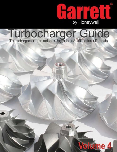
<strong>Garrett</strong> ®<br />
by Honeywell<br />
<br />
www.TurboBy<strong>Garrett</strong>.com<br />
Honeywell
<strong>Garrett</strong> ®<br />
by Honeywell<br />
Table of Contents<br />
Why <strong>Garrett</strong> ® ? - History and Testing.................................................pg 4<br />
<strong>Garrett</strong> ® Technology..........................................................................pg 5<br />
Turbo Basics.....................................................................................pg 6<br />
Turbo Tech; How to Choose the Right Turbo - Gasoline ..................pg 9<br />
Turbo Tech; How to Choose the Right Turbo - Diesel.......................pg 13<br />
Turbo System Optimization ..............................................................pg 16<br />
Troubleshooting.................................................................................pg 19<br />
Displacement Charts ........................................................................pg 20<br />
<strong>Garrett</strong> ® GT & GTX Turbochargers...................................................pg 21<br />
T-Series Ball Bearing Upgrades........................................................pg 76<br />
Mitsubishi Evolution X Upgrade Kit...................................................pg 77<br />
Diesel PowerMax TM Upgrade Kits.....................................................pg 78<br />
Drag <strong>Racing</strong>-Specific Turbos............................................................pg 81<br />
Turbocharger Connection Sizes & Dimensions.................................pg 82<br />
Wastegates & Blow-Off Valves.........................................................pg 87<br />
<strong>Garrett</strong> ® Accessories.........................................................................pg 88<br />
Intercoolers.......................................................................................pg 89<br />
<strong>Garrett</strong> ® GT Turbocharger Index.......................................................pg 90<br />
Honeywell<br />
www.TurboBy<strong>Garrett</strong>.com
Why <strong>Garrett</strong> ® ?<br />
<strong>Garrett</strong> ®<br />
by Honeywell<br />
<strong>Garrett</strong> ® History<br />
The heritage of the turbo business began in 1936 when<br />
young Cliff <strong>Garrett</strong> formed his company in a tiny, one-room<br />
office in Los Angeles. With encouragement and financial<br />
support from friends like Jack<br />
Northrop and Harry Wetzel, plus<br />
$5,000 he borrowed on his own,<br />
<strong>Garrett</strong> founded the company that<br />
would later become the <strong>Garrett</strong><br />
Corporation. Number of employees:<br />
1. Number of customers: 1.<br />
Today, that business couldn’t<br />
be more different. Over time, the<br />
turbocharging business spun off to<br />
establish itself as a serious player<br />
in the engine boosting industry.<br />
<strong>Garrett</strong> ® product is produced by over 6,000 employees and<br />
serves the leading global engine and vehicle manufacturers,<br />
including Audi, BMW, Chrysler, Daimler Benz, DDC, Fiat,<br />
Ford, General Motors, International Truck Co, Nissan,<br />
Peugeot, Renault, Saab and Volkswagen.<br />
Through names such as AiResearch, AlliedSignal, and the<br />
Honeywell of today, <strong>Garrett</strong> ® has sustained its reputation for<br />
revolutionizing turbocharger technologies generation after<br />
generation. From its long list of industry firsts to its leadingedge<br />
patented dual-ball bearing turbos for high performance<br />
vehicles, <strong>Garrett</strong> ® develops and manufactures the same<br />
cutting-edge boosting expertise that goes into all <strong>Garrett</strong> ®<br />
products. The fact that <strong>Garrett</strong> ® turbochargers are the<br />
preferred choice of leading original equipment manufacturers<br />
and many top race teams in World Rally, American Le Mans,<br />
24 Hours of Le Mans, and Pikes Peak is a telling example.<br />
Today, <strong>Garrett</strong> ® continues to redefine the art and science<br />
of boosting technology with advanced air management<br />
systems for the full spectrum of modern engines. With over<br />
30,000 turbos produced EVERY DAY, you know the <strong>Garrett</strong> ®<br />
name is one you can trust.<br />
<strong>Garrett</strong> ® Testing<br />
A turbocharger is a highly technical product that requires<br />
superior design and intensive capital to produce. It must<br />
meet the most severe requirements that only a world-class<br />
manufacturer like Honeywell’s <strong>Garrett</strong> ® brand can achieve.<br />
<strong>Garrett</strong> ® is one of the few brands that subjects its turbos<br />
to several OE qualification tests that ensure that “<strong>Garrett</strong>” is<br />
only stamped on safe and reliable turbos! Some of these<br />
tests include:<br />
* On-Engine Durability - A 1,000-hour general turbocharger<br />
durability test that is run on-engine in an engineering<br />
laboratory.<br />
* Compressor & Turbine Housing Containment - A compressor/turbine<br />
wheel is set to “hub” burst at a specific speed.<br />
No portion of the wheel is allowed to penetrate a “containment<br />
shroud” surrounding the turbocharger; a test to ensure<br />
safety.<br />
* Shaft Motion - The<br />
maximum tolerances<br />
of the bearing system<br />
are tested for rotordynamic<br />
stability beyond<br />
the maximum<br />
turbocharger operating<br />
speed. This means no<br />
bearing problems and<br />
a long turbo life.<br />
* Compressor & Turbine Performance - The entire operating<br />
range of both the compressor and turbine are mapped on a<br />
“Performance Gas Stand.” These test cells are calibrated to<br />
strict standards to assure accuracy and consistency.<br />
* Heat Soakback - A turbocharger instrumented with thermocouples<br />
is taken<br />
beyond maximum operating<br />
temperature<br />
and shut down hard!<br />
Repeat this test four<br />
more times and make<br />
sure maximum temperatures<br />
stay within<br />
strict limits to avoid oil<br />
“coking” or build up inside<br />
the center housing. This is particularly critical for high<br />
temperature gasoline applications.<br />
* Thermal Cycle - A 200-hour endurance test that cycles the<br />
turbocharger from low temperature to “glowing red” every 10<br />
minutes. To ensure long turbo life, no cracking of the turbine<br />
housing or distortion of the heat shroud is accepted.<br />
* Rotor Inertia - A measurement made to document the rotational<br />
inertia of the compresor and turbine wheels. <strong>Garrett</strong> ®<br />
brand products are known for their high flow / low inertia<br />
characteristics.<br />
Vistit www.TurboBy<strong>Garrett</strong>.com for complete test list.<br />
<br />
www.TurboBy<strong>Garrett</strong>.com<br />
Honeywell
<strong>Garrett</strong> ®<br />
by Honeywell<br />
<strong>Garrett</strong> ® Technology<br />
<strong>Garrett</strong> ® GTX Turbochargers<br />
The next step in the evolution of the turbocharger is here!<br />
<strong>Garrett</strong> ® GTX Turbos feature all new compressor wheels with<br />
next generation aerodynamics and improved efficiency to<br />
deliver wicked performance!<br />
<strong>Garrett</strong> ® GTX Turbochargers provide higher flow and greater<br />
boost pressure ratios beyond the world-class <strong>Garrett</strong> ® GT<br />
Series compressor wheels.<br />
* 10%+ Gain in flow over traditional GT compressor<br />
wheel designs<br />
* 10%+ Higher pressure ratio compared to traditional GT<br />
compressor wheel designs<br />
* Forged, fully machined wheels<br />
(billet) for expedited release<br />
* 11 Full-blade design for<br />
improved efficiency and ultra<br />
quiet operation<br />
* Outline interchangeable with<br />
<strong>Garrett</strong> ® GT Series turbos<br />
* <strong>Garrett</strong> ® OE-quality for<br />
unbeatable reliability<br />
<strong>Garrett</strong> ® Dual Ball Bearing<br />
The journal bearing has long been the workhorse of the<br />
turbocharger. However, in the 1990’s, <strong>Garrett</strong> ® engineers developed<br />
a radically new and extremely efficient turbocharger.<br />
With wheel and bearing advances that provide crisp and strong<br />
throttle response up to 15% faster than traditional bearings, a<br />
<strong>Garrett</strong> ® turbo will accelerate your vehicle more quickly than<br />
ever.<br />
The patented dual ball bearing design also requires less oil to<br />
provide adequate lubrication. This in turn lowers oil volume and<br />
the chances for seal leakage. The lessened need for oil also<br />
makes the bearings more tolerant to marginal lube conditions<br />
and diminishes the possibility of turbocharger failure on engine<br />
shut down.<br />
The <strong>Garrett</strong> ® dual ball bearing cartridge gives better damping<br />
and control over shaft motion allowing enhanced reliability for both everyday and extreme driving conditions. The opposed<br />
angular contact bearing cartridge eliminates the need for the thrust bearing, commonly the weak link in the turbo bearing<br />
system. The bearing system in the GT turbocharger allows for improved shaft stability and less drag throughout the speed<br />
range.<br />
While T-series turbos typically contain 54 components, GT turbos have an average of only 29. The 45% decrease in parts<br />
diminishes the opportunity for failure and results in smoother operation.<br />
A <strong>Garrett</strong> ® Turbo for Your Vehicle?<br />
<strong>Garrett</strong> ® is the only brand to offer a searchable database for turbo kits using its product.<br />
Visit www.TurboBy<strong>Garrett</strong>.com and enter your vehicle into our Turbo Application Search Engine (TASE) to find a turbo kit<br />
available for it using <strong>Garrett</strong> ® turbochargers!<br />
Honeywell<br />
www.TurboBy<strong>Garrett</strong>.com
Turbo Basics<br />
<strong>Garrett</strong> ®<br />
by Honeywell<br />
How a Turbo System Works<br />
Engine power is proportional to the<br />
amount of air and fuel that can get into<br />
the cylinders. All else being equal,<br />
larger engines flow more air and as<br />
such will produce more power.<br />
If we want our small engine to<br />
perform like a big engine, or simply<br />
make our bigger engine produce<br />
more power, our ultimate objective is<br />
to draw more air into the cylinder. By<br />
installing a <strong>Garrett</strong> ® turbocharger, the<br />
power and performance of an engine<br />
can be dramatically increased.<br />
The layout of the turbocharger<br />
in a given application is critical to a<br />
properly performing system.<br />
So how does a turbocharger get<br />
more air into the engine? Let us first<br />
look at the schematic to the upper<br />
right.<br />
• Ambient air passes through the air<br />
filter (not shown) before entering the<br />
compressor [1].<br />
• The air is then compressed which<br />
raises the air’s density<br />
(mass / unit volume) [2].<br />
• Many turbocharged engines have a<br />
charge air cooler (aka intercooler)<br />
[3] that cools the compressed air to<br />
further increase its density and to<br />
increase resistance to detonation.<br />
• After passing through the intake<br />
manifold [4], the air enters<br />
the engine’s cylinders, which<br />
contain a fixed maximum<br />
volume. Since the air is at an<br />
elevated density, each cylinder<br />
can contain an increased mass<br />
of air. Higher air mass flow<br />
rate allows a higher fuel flow<br />
rate (with similar air/fuel ratio).<br />
Combusting more fuel results in<br />
more power being produced for<br />
a given size or displacement.<br />
• After the fuel is burned in<br />
the cylinder, it is expelled<br />
during the cylinder’s exhaust<br />
stroke into the exhaust manifold<br />
[5].<br />
• The high temperature gas<br />
then continues on to the<br />
turbine [6]. The turbine creates<br />
backpressure on the engine<br />
which means engine exhaust<br />
pressure is higher than<br />
atmospheric pressure.<br />
• A pressure and temperature<br />
drop occurs (expansion) across<br />
the turbine [7], which harnesses<br />
the energy of the exhaust gas to<br />
provide the power necessary to drive<br />
the compressor.<br />
What are the Components of a<br />
Turbocharger?<br />
• Compressor Housing<br />
• Turbine Housing<br />
• Center Housing and Rotating<br />
Assembly (CHRA)<br />
•<br />
•<br />
•<br />
•<br />
•<br />
•<br />
Compressor Wheel<br />
Turbine Wheel Assembly<br />
(wheel and shaft)<br />
Backplate<br />
Bearing System<br />
Oil Inlet<br />
Oil Outlet<br />
<br />
www.TurboBy<strong>Garrett</strong>.com<br />
Honeywell
<strong>Garrett</strong> ®<br />
by Honeywell<br />
Turbo Basics<br />
How Do I Choose the Right Turbo?<br />
Selecting the proper turbocharger for your specific<br />
application requires many inputs. With decades of collective<br />
turbocharging experience, the <strong>Garrett</strong> ® Performance<br />
Distributors can assist in selecting the right turbocharger for<br />
your application.<br />
The primary input in determining which turbocharger<br />
is appropriate is to have a target horsepower in mind.<br />
This should be as realistic as possible for the application.<br />
Remember that engine power is generally proportional to<br />
air and fuel flow. Thus, once you have a target power level<br />
identified, you begin to hone in on the turbocharger size,<br />
which is highly dependent on air flow requirements.<br />
Other important factors include the type of application. An<br />
autocross car, for example, requires rapid boost response.<br />
A smaller turbocharger or smaller turbine housing would be<br />
most suitable for this application. While this will sacrifice<br />
ultimate power due to increased exhaust backpressure at<br />
higher engine speeds, boost response of the small turbo will<br />
be excellent.<br />
Alternatively, on a car dedicated to track days, peak<br />
horsepower is a higher priority than low-end torque. Plus,<br />
engine speeds tend to be consistently higher. Here, a<br />
larger turbocharger or turbine housing will provide reduced<br />
backpressure but less immediate low-end response. This<br />
is a welcome trade-off given the intended operating<br />
conditions.<br />
Selecting the turbocharger for your application goes<br />
beyond “how much boost” you want to run. Defining your<br />
target power level and the primary use for the application<br />
are the first steps in selecting the best <strong>Garrett</strong> ® Turbo<br />
for your vehicle. This catalog includes the formulas and<br />
considerations needed to corectly match a turbo to either<br />
your gasoline or diesel engine!<br />
What is A/R?<br />
A/R describes a geometric characteristic of all compressor<br />
and turbine housings. It is defined as the inlet cross-sectional<br />
area divided by the radius from the turbo centerline to the<br />
centroid of that area.<br />
Compressor A/R - Compressor performance is largely<br />
insensitive to changes in A/R, but generally larger A/R housings<br />
are used to optimize the performance for low boost applications,<br />
and smaller housings<br />
are used for high boost<br />
applications. Usually there<br />
are not A/R options available<br />
for compressor housings.<br />
Turbine A/R – Turbine<br />
performance is greatly<br />
affected by changing the<br />
A/R of the housing. Turbine<br />
A/R is used to adjust the<br />
flow capacity of the turbine.<br />
Using a smaller A/R will increase the exhaust gas velocity<br />
into the turbine wheel, causing the wheel to spin faster at<br />
lower engine RPMs giving a quicker boost rise. This will<br />
also tend to increase exhaust backpressure and reduce the<br />
max power at high RPM. Conversely, using a larger A/R<br />
will lower exhaust gas velocity and delay boost rise, but the<br />
lower backpressure will give better high-RPM power. When<br />
deciding between A/R options, be realistic with the intended<br />
vehicle use and use the A/R to bias the performance toward<br />
the desired powerband.<br />
What is Wheel Trim?<br />
Trim is an area ratio used to describe both turbine and<br />
compressor wheels. Trim is calculated using the inducer and<br />
exducer diameters.<br />
Trim = (Inducer 2 /Exducer 2 ) x 100<br />
Example:<br />
Inducer diameter = 88mm<br />
Exducer diameter = 117.5mm<br />
Trim = (88 2 /117.5 2 ) x 100= 56 Trim<br />
As trim is increased, the wheel can support more air/gas flow.<br />
Compressor Wheel Trim = (Inducer 2 /Exducer 2 ) x 100<br />
Turbine Wheel Trim = (Exducer 2 /Inducer 2 ) x 100<br />
Honeywell<br />
www.TurboBy<strong>Garrett</strong>.com
Turbo Basics<br />
<strong>Garrett</strong> ®<br />
by Honeywell<br />
Other Components<br />
Blow-Off (Bypass) Valves<br />
The blow-off valve (BOV) is a<br />
pressure relief device on the intake<br />
tract to prevent the turbo’s compressor<br />
from going into surge. The BOV should<br />
be installed between the compressor<br />
discharge and the throttle body,<br />
preferably downstream of the charge<br />
air cooler (if equipped).<br />
When the throttle is closed rapidly, the<br />
this energy (e.g. exhaust flow) reduces<br />
the power driving the turbine wheel<br />
to match the power required for a<br />
given boost level. Similar to the BOV,<br />
the wastegate uses boost pressure<br />
and spring force to regulate the flow<br />
bypassing the turbine.<br />
<strong>Garrett</strong> ® ball bearing turbochargers<br />
require less oil than journal bearing<br />
turbos. Therefore an oil inlet restrictor<br />
is recommended if you have oil<br />
pressure over approximately 40 psig.<br />
The oil outlet should be plumbed to the<br />
oil pan above the oil level (for wet sump<br />
systems). Since the oil drain is gravity<br />
fed, it is important that the oil outlet<br />
points downward, and that the drain<br />
tube does not become horizontal or go<br />
“uphill” at any point.<br />
airflow is quickly reduced, causing flow<br />
instability and pressure fluctuations.<br />
These rapidly cycling pressure<br />
fluctuations are the audible evidence<br />
of surge. Surge can eventually lead to<br />
bearing failure due to the high loads<br />
associated with it.<br />
Blow-off valves use a combination<br />
of manifold pressure signal and spring<br />
force to detect when the throttle is<br />
closed. When the throttle is closed<br />
rapidly, the BOV vents boost from<br />
the intake tract to atmosphere or<br />
recirculates it to relieve the pressure<br />
from the turbo, eliminating surge.<br />
Wastegates<br />
On the exhaust side, a wastegate<br />
provides a means to control the boost<br />
pressure generated by the turbocharger<br />
by controlling the turbocharger shaft<br />
speed. Some commercial diesel<br />
applications do not use a wastegate at<br />
all. This type of system is called a free<br />
floating turbocharger.<br />
However, the vast majority of gasoline<br />
performance applications require a<br />
wastegate. There are two configurations<br />
of wastegates: internal and external.<br />
Both internal and external wastegates<br />
provide a means for exhaust gas to<br />
bypass the turbine wheel. Bypassing<br />
Internal wastegates are built into<br />
the turbine housing and consist of a<br />
“flapper” valve, crank arm, rod end,<br />
and pneumatic actuator. It is important<br />
to connect this actuator only to boost<br />
pressure since it is not designed to<br />
handle vacuum and as such should<br />
not be referenced to an intake<br />
manifold.<br />
External wastegates are added<br />
to the exhaust plumbing on the<br />
exhaust manifold or header. The<br />
advantage of external wastegates<br />
is that the bypassed flow can<br />
be reintroduced into the exhaust<br />
stream further downstream of the<br />
turbine. This improves the turbine’s<br />
performance. On racing applications,<br />
this wastegated exhaust flow can be<br />
vented directly to atmosphere.<br />
Oil & Water Plumbing<br />
The intake and exhaust plumbing<br />
often receives the focus, leaving the<br />
oil and water plumbing neglected.<br />
Following a hot shutdown of a<br />
turbocharger, heat soak begins. This<br />
means that the heat in the head, exhaust<br />
manifold, and turbine housing raises<br />
the temperature of the turbo’s center<br />
housing. These extreme temperatures<br />
can result in oil coking.<br />
Water-cooled center housings<br />
were introduced to minimize the<br />
effects of heat soak-back. These<br />
use unpressurized coolant from the<br />
engine to act as a heat sink after<br />
engine shutdown, preventing the oil<br />
from coking. The water lines utilize<br />
a thermal siphon effect to reduce the<br />
peak heat soak-back temperature after<br />
key-off. The layout of the pipes should<br />
eliminate peaks and troughs with the<br />
(cool) water inlet on the low side. To<br />
help this along, it is advantageous to<br />
tilt the turbocharger approximately 25°<br />
about the axis of shaft rotation.<br />
<strong>Garrett</strong> ® offers many turbos that are<br />
water-cooled for enhanced durability.<br />
Want to learn more?<br />
Visit http://www.TurboBy<strong>Garrett</strong>.com<br />
and check out the Turbo Tech section<br />
for more great articles!<br />
<br />
www.TurboBy<strong>Garrett</strong>.com<br />
Honeywell
<strong>Garrett</strong> ®<br />
by Honeywell<br />
Turbo Selection - Gas<br />
This article is more involved and will describe parts of the<br />
compressor map, how to estimate pressure ratio and mass flow<br />
rate for your engine as well as how to plot the points on the maps to<br />
help choose the right turbocharger. Have your calculator handy!<br />
Parts of the Compressor Map<br />
The compressor map is a graph that describes a particular compressor’s<br />
performance characteristics, including efficiency, mass<br />
flow range, boost pressure capability, and turbo speed. Shown below<br />
is a figure that identifies aspects of a typical compressor map:<br />
Pressure Ratio<br />
Pressure Ratio ( ) is defined as the Absolute outlet pressure<br />
divided by the Absolute Inlet Pressure.<br />
Where:<br />
= Pressure Ratio<br />
P1c = Compressor Inlet<br />
Pressure<br />
P2c = Compressor Discharge<br />
Pressure<br />
It is important to use<br />
units of Absolute Pressure<br />
for both P1c and<br />
P2c. Remember that<br />
Absolute Pressure at<br />
sea level is 14.7 psia (in<br />
units of psia, the “a” refers<br />
to “absolute”). This<br />
is referred to as standard<br />
atmospheric pressure at<br />
standard conditions.<br />
Gauge Pressure (in<br />
units of psig, the g refers<br />
to “gauge”) measures the pressure above atmospheric, so a<br />
Gauge Pressure reading at atmospheric conditions will read zero.<br />
Boost gauges measure the manifold pressure relative to atmospheric<br />
pressure, and thus are measuring Gauge Pressure. This<br />
is important when determining P2c. For example, a reading of 12<br />
psig on a boost gauge means that the air pressure in the manifold<br />
is 12 psi above atmospheric pressure.<br />
For a day at standard atmospheric conditions:<br />
12 psig + 14.7 psia = 26.7 psi Absolute Pressure in the manifold,<br />
the Pressure Ratio at this condition can now be calculated:<br />
26.7 psia / 14.7 psia = 1.82<br />
However, this assumes there is no adverse impact of the air filter<br />
assembly at the compressor inlet.<br />
In determining Pressure Ratio, the Absolute Pressure at the<br />
compressor inlet (P2c) is often LESS than the Ambient Pressure,<br />
especially at high load. Why is this? Any restriction (caused by<br />
the air filter or restrictive ducting) will result in a “depression,”<br />
or pressure loss, upstream of the compressor that needs to be<br />
accounted for when determining pressure ratio. This depression<br />
can be 1 psig or more on some intake systems. In this<br />
case P1c on a standard day is:<br />
14.7psia – 1 psig = 13.7 psia at compressor inlet<br />
Taking into account the 1 psig intake depression, the pressure<br />
ratio is now.<br />
(12 psig + 14.7 psia) / 13.7 psia = 1.95.<br />
That’s great, but what if you’re not at sea level? In this case,<br />
simply substitute the actual atmospheric pressure in place of the<br />
14.7 psi in the equations above to give a more accurate calculation.<br />
At higher elevations, this can have a significant effect on pressure<br />
ratio.<br />
For example, at Denver’s 5000 feet elevation, the atmospheric<br />
pressure is typically around 12.4 psia. In this case, the pressure<br />
ratio calculation, taking into account the intake depression, is:<br />
(12 psig + 12.4 psia) / (12.4 psia – 1 psig) = 2.14<br />
Compared to the 1.82 pressure ratio calculated originally, this<br />
is a big difference.<br />
As you can see in these examples, pressure ratio depends on a<br />
lot more than just boost.<br />
Mass Flow Rate<br />
Mass Flow Rate is the mass of air flowing through a compressor<br />
(and engine!) over a given period of time and is commonly<br />
expressed as lb/min (pounds per minute). Mass flow can be<br />
physically measured, but in many cases it is sufficient to estimate<br />
the mass flow for choosing the proper turbo.<br />
Many people use Volumetric Flow Rate (expressed in cubic feet<br />
per minute, CFM or ft 3 /min) instead of mass flow rate. Volumetric<br />
flow rate can be converted to mass flow by multiplying by the air<br />
density. Air density at sea level is 0.076lb/ft 3 .<br />
What is my mass flow rate? As a very general rule, turbocharged<br />
gasoline engines will generate 9.5-10.5 horsepower (as measured<br />
at the flywheel) for each lb/min of airflow. So, an engine with a target<br />
peak horsepower of 400 HP will require 36-44 lb/min of airflow to<br />
achieve that target. This is just a rough first approximation to help<br />
narrow the turbo selection options.<br />
Surge Line<br />
Surge is the left hand boundary of the compressor map.<br />
Operation to the left of this line represents a region of flow<br />
instability. This region is characterized by mild flutter to wildly<br />
fluctuating boost and “barking” from the compressor. Continued<br />
operation within this region can lead to premature turbo failure<br />
due to heavy thrust loading.<br />
Surge is most commonly experienced when one of two<br />
situations exist. The first and most damaging is surge under load.<br />
It can be an indication that your compressor is too large. Surge<br />
is also commonly experienced when the throttle is quickly closed<br />
after boosting. This occurs because mass flow is drastically<br />
reduced as the throttle is closed, but the turbo is still spinning<br />
and generating boost. This immediately drives the operating<br />
point to the far left of the compressor map, right into surge. Surge<br />
will decay once the turbo speed finally slows enough to reduce<br />
the boost and move the operating point back into the stable<br />
region. This situation is commonly addressed by using a Blow-<br />
Off Valve (BOV) or bypass valve. A BOV functions to vent intake<br />
pressure to atmosphere so that the mass flow ramps down<br />
smoothly, keeping the compressor out of surge. In the case of a<br />
recirculating bypass valve, the airflow is recirculated back to the<br />
compressor inlet.<br />
Honeywell<br />
www.TurboBy<strong>Garrett</strong>.com
Turbo Selection - Gas<br />
<strong>Garrett</strong> ®<br />
by Honeywell<br />
A Ported Shroud Compressor (see Fig. 2) is a feature that is<br />
incorporated into the compressor housing. It functions to move<br />
the surge line further to the left (see Fig. 3) by allowing some<br />
airflow to exit the wheel through the port to keep surge from<br />
occurring. This provides additional useable range and allows<br />
a larger compressor to be used for higher flow requirements<br />
without risking running the compressor into a dangerous surge<br />
condition. The presence of<br />
the ported shroud usually<br />
has a minor negative impact<br />
on compressor efficiency.<br />
The Choke Line is the<br />
right hand boundary of<br />
the compressor map. For<br />
<strong>Garrett</strong> ® maps, the choke<br />
line is typically defined by the<br />
point where the efficiency<br />
drops below 58%. In<br />
addition to the rapid drop of<br />
compressor efficiency past<br />
this point, the turbo speed<br />
Fig 2<br />
will also be approaching or<br />
exceeding the allowable limit.<br />
If your actual or predicted<br />
operation is beyond this<br />
limit, a larger compressor is<br />
necessary.<br />
Turbo Speed Lines are<br />
lines of constant turbo speed.<br />
Turbo speed for points<br />
between these lines can be<br />
estimated by interpolation. As<br />
turbo speed increases, the<br />
pressure ratio increases and/<br />
or mass flow increases. As<br />
indicated above in the choke<br />
line description, the turbo<br />
Fig 3<br />
speed lines are very close together at the far right edge of the<br />
map. Once a compressor is operating past the choke limit, turbo<br />
speed increases very quickly and a turbo over-speed condition is<br />
very likely.<br />
Efficiency Islands are concentric regions on the maps that<br />
represent the compressor efficiency at any point on the map. The<br />
smallest island near the center of the map is the highest or peak<br />
efficiency island. As the rings move out from there, the efficiency<br />
drops by the indicated amount until the surge and choke limits are<br />
reached.<br />
Plotting Your Data on the Compressor Map<br />
In this section, methods to calculate mass flow rate and boost<br />
pressure required to meet a horsepower target are presented.<br />
This data will then be used to choose the appropriate compressor<br />
and turbocharger. Having a Horsepower Target in mind is a vital<br />
part of the process. In addition to being necessary for calculating<br />
mass flow and boost pressure, a Horsepower Target is required<br />
for choosing the right fuel injectors, fuel pump and regulator, and<br />
other engine components.<br />
Estimating Required Air Mass Flow and Boost Pressures to<br />
reach a Horsepower Target.<br />
Things you need to know:<br />
-Horsepower Target<br />
-Engine Displacement<br />
-Maximum RPM<br />
-Ambient conditions (temperature and barometric<br />
pressure. Barometric pressure is usually given as inches of mercury<br />
and can be converted to psi by dividing by 2)<br />
Things you need to estimate:<br />
· Engine Volumetric Efficiency. Typical numbers for peak Volumetric<br />
Efficiency (VE) range in the 95%-99% for modern 4-valve heads, to<br />
88%-95% for 2-valve designs. If you have a torque curve for your<br />
engine, you can use this to estimate VE at various engine speeds.<br />
On a well-tuned engine, the VE will peak at the torque peak, and<br />
this number can be used to scale the VE at other engine speeds.<br />
A 4-valve engine will typically have higher VE over more of its rev<br />
range than a 2-valve engine.<br />
· Intake Manifold Temperature. Compressors with higher efficiency<br />
give lower manifold temperatures. Manifold temperatures of<br />
intercooled setups are typically 100 - 130 degrees F, while nonintercooled<br />
values can reach from 175-300 degrees F.<br />
· Brake Specific Fuel Consumption (BSFC). BSFC describes the<br />
fuel flow rate required to generate each horsepower. General<br />
values of BSFC for turbocharged gasoline engines range from 0.50<br />
to 0.60 and higher.<br />
The units of BSFC are<br />
Lower BSFC means that the engine requires less fuel to generate<br />
a given horsepower. Race fuels and aggressive tuning are required<br />
to reach the low end of the BSFC range described above.<br />
For the equations below, we will divide BSFC by 60 to convert<br />
from hours to minutes.<br />
To plot the compressor operating point, first calculate airflow:<br />
Where:<br />
Wa= Airflow actual (lb/min)<br />
HP = Horsepower Target (flywheel)<br />
= Air/Fuel Ratio<br />
= Brake Specific Fuel Consumption = ( ) ÷ 60 (to<br />
convert from hours to minutes)<br />
EXAMPLE:<br />
I have an engine that I would like to make 400HP, I want to<br />
choose an air/fuel ratio of 12 and use a BSFC of 0.55. Plugging<br />
these numbers into the formula from above:<br />
of air.<br />
Thus, a compressor map that has the capability of at least 44<br />
pounds per minute of airflow capacity is a good starting point.<br />
Note that nowhere in this calculation did we enter any engine<br />
displacement or RPM numbers. This means that for any engine,<br />
in order to make 400 HP, it needs to flow about 44 lb/min (this<br />
assumes that BSFC remains constant across all engine types).<br />
Naturally, a smaller displacement engine will require more boost or<br />
higher engine speed to meet this target than a larger engine will. So<br />
how much boost pressure would be required?<br />
10 www.TurboBy<strong>Garrett</strong>.com<br />
Honeywell
<strong>Garrett</strong> ®<br />
by Honeywell<br />
Turbo Selection - Gas<br />
Calculate manifold pressure required to meet the Horsepower, or<br />
flow target:<br />
Where:<br />
· MAPreq = Manifold Absolute Pressure (psia) required to meet the<br />
horsepower target<br />
· Wa = Airflow actual(lb/min)<br />
· R = Gas Constant = 639.6<br />
· Tm = Intake Manifold Temperature (degrees F)<br />
· VE = Volumetric Efficiency<br />
· N = Engine speed (RPM)<br />
· Vd = engine displacement (Cubic Inches, convert from liters to CI<br />
by multiplying by 61.02, ex. 2.0 liters * 61.02 = 122 CI)<br />
EXAMPLE:<br />
To continue the example above, let’s consider a 2.0 liter engine<br />
with the following description:<br />
· Wa = 44 lb/min as previously calculated<br />
· Tm = 130 degrees F<br />
· VE = 92% at peak power<br />
· N = 7200 RPM<br />
· Vd = 2.0 liters * 61.02 = 122 CI<br />
= 41.1 psia (remember, this is<br />
Absolute Pressure. Subtract Atmospheric Pressure to get Gauge<br />
Pressure (aka boost):<br />
41.1 psia – 14.7 psia (at sea level) = 26.4 psig boost<br />
As a comparison let’s repeat the calculation for a larger<br />
displacement 5.0L (4942 cc/302 CI) engine.<br />
Where:<br />
· Wa = 44 lb/min as previously calculated<br />
· Tm = 130 degrees F<br />
· VE = 85% at peak power (it is a pushrod V-8)<br />
· N = 6000 RPM<br />
· Vd = 4.942*61.02= 302 CI<br />
= 21.6 psia (or 6.9 psig boost)<br />
This example illustrates that in order to reach the horsepower<br />
target of 400 hp, a larger engine requires lower manifold pressure<br />
but still needs 44lb/min of airflow. This can have a very significant<br />
effect on choosing the correct compressor.<br />
With Mass Flow and Manifold Pressure, we are nearly ready to<br />
plot the data on the compressor map. The next step is to determine<br />
how much pressure loss exists between the compressor and the<br />
manifold. The best way to do this is to measure the pressure<br />
drop with a data acquisition system, but many times that is not<br />
practical.<br />
Depending upon flow rate, charge air cooler characteristics,<br />
piping size, number/quality of the bends, throttle body restriction,<br />
etc., the plumbing pressure drop can be estimated. This can be 1<br />
psi or less for a very well designed system. On certain restrictive<br />
OEM setups, especially those that have now higher-than-stock<br />
airflow levels, the pressure drop can be 4 psi or greater.<br />
For our examples we will assume that there is a 2 psi loss. So to<br />
determine the Compressor Discharge Pressure (P2c), 2 psi will be<br />
added to the manifold pressure calculated above.<br />
Where:<br />
· P2c = Compressor Discharge Pressure (psia)<br />
· MAP = Manifold Absolute Pressure (psia)<br />
· ΔPloss = Pressure Loss Between the Compressor and the<br />
Manifold (psi)<br />
For the 2.0 L engine:<br />
For the 5.0 L engine:<br />
= 43.1 psia<br />
= 23.6 psia<br />
Remember our discussion on inlet depression in the Pressure<br />
Ratio discussion earlier, we said that a typical value might be 1 psi,<br />
so that is what will be used in this calculation. For this example,<br />
assume that we are at sea level, so Ambient Pressure is 14.7<br />
psia.<br />
We will need to subtract the 1 psi pressure loss from the ambient<br />
pressure to determine the Compressor Inlet Pressure (P1).<br />
Where:<br />
· P1c = Compressor Inlet Pressure (psia)<br />
· Pamb = Ambient Air Pressure (psia)<br />
· ΔPloss = Pressure Loss due to Air Filter/Piping (psi)<br />
P1c = 14.7 - 1 = 13.7 psia<br />
With this, we can calculate Pressure Ratio ( ) using the<br />
equation.<br />
For the 2.0 L engine: = 3.14<br />
For the 5.0 L engine: = 1.72<br />
We now have enough information to plot these operating points<br />
on the compressor map. First we will try a GT2860RS. This turbo<br />
has a 60mm, 60 trim compressor wheel.<br />
Clearly this<br />
c o m p r e s s o r<br />
is too small,<br />
as both points<br />
are positioned<br />
far to the right<br />
and beyond the<br />
c o m p r e s s o r ’s<br />
choke line.<br />
Honeywell<br />
www.TurboBy<strong>Garrett</strong>.com<br />
11
Turbo Selection - Gas<br />
<strong>Garrett</strong> ®<br />
by Honeywell<br />
Another potential<br />
candidate might<br />
be the <strong>Garrett</strong> ®<br />
GT3076R. This<br />
turbo has a 76mm,<br />
56 trim compressor<br />
wheel.<br />
This is much<br />
better; at least both<br />
points are on the<br />
map! Let’s look at<br />
each point in more<br />
detail.<br />
For the 2.0L<br />
engine this point is<br />
in a very efficient<br />
area of the map,<br />
but since it is in the<br />
center of the map,<br />
there would be a<br />
concern that at lower<br />
engine speeds that it would be near or over the surge line. This<br />
might be ok for a high-rpm-biased powerband that might be used<br />
on a racing application, but a street application would be better<br />
served by a different compressor.<br />
For the 5.0L engine, this looks like a very good street-biased<br />
powerband, with the lower engine speeds passing through the<br />
highest efficiency zone on the map, and plenty of margin to stay<br />
clear of surge. One area of concern would be turbo overspeed when<br />
revving the engine past peak power. A larger compressor would<br />
place the operating<br />
point nearer to the<br />
center of the map<br />
and would give some<br />
additional benefit to<br />
a high-rpm-biased<br />
powerband. We’ll<br />
look at a larger<br />
compressor for the<br />
5.0L after we figure<br />
out a good street<br />
match for the 2.0L<br />
engine.<br />
So now lets look at<br />
a <strong>Garrett</strong> ® GT3071R,<br />
which uses a 71mm,<br />
56 trim compressor<br />
wheel.<br />
For the 2.0L<br />
engine, this is a better<br />
mid-range-oriented<br />
compressor. The operating point is shifted a bit towards the choke<br />
side of the map and this provides additional surge margin. The<br />
lower engine speeds will now pass through the higher efficiency<br />
zones and give excellent performance and response.<br />
For the 5.0L engine, the compressor is clearly too small and<br />
would not be considered.<br />
Now that we have arrived at an acceptable compressor for the<br />
2.0L engine, lets calculate a lower rpm point to plot on the map to<br />
better get a feel for what the engine operating line will look like. We<br />
can calculate this using the following formula:<br />
We’ll choose the engine speed at which we would expect to see<br />
peak torque, based on experience or an educated guess. In this<br />
case we’ll choose 5000rpm.<br />
Where:<br />
· Wa = Airflow actual (lb/min)<br />
· MAP = Manifold Absolute Pressure (psia) =41.1 psia<br />
· R = Gas Constant = 639.6<br />
· Tm = Intake Manifold Temperature (degrees F) =130<br />
· VE = Volumetric Efficiency = 0.92<br />
· N = Engine speed (RPM) = 5000rpm<br />
· Vd = engine displacement (Cubic Inches, convert from liters to CI<br />
by multiplying by 61, ex. 2.0 liters * 61 = 122 CI)<br />
= 34.1 lb/min<br />
Plotting this on the GT3071R compressor map demonstrates the<br />
following operating points.<br />
This provides a good<br />
representation of the<br />
operating line at that<br />
boost level, which is<br />
well suited to this map.<br />
At engine speeds lower<br />
than 5000 rpm the boost<br />
pressure will be lower,<br />
and the pressure ratio<br />
would be lower, to keep<br />
the compressor out of<br />
surge.<br />
Back to the 5.0L<br />
engine. Let’s look at<br />
a larger compressor’s<br />
map. This time we<br />
will try a GT3582R<br />
with an 82mm, 56 trim<br />
compressor.<br />
Here, compared to<br />
the GT3076R, we can<br />
see that this point is not<br />
quite so deep into choke<br />
and will give better highrpm<br />
performance than<br />
the 76mm wheel. A<br />
further increase in wheel<br />
size would provide<br />
even better high-rpm<br />
performance, but at the<br />
cost of low- and midrange<br />
response and<br />
drivability.<br />
Hopefully this<br />
provided a basic idea of<br />
what a compressor map<br />
displays and how to<br />
choose a compressor. If<br />
real data is available to<br />
be substituted in place of estimation, more accurate results can<br />
be generated.<br />
12 www.TurboBy<strong>Garrett</strong>.com<br />
Honeywell
<strong>Garrett</strong> ®<br />
by Honeywell<br />
Turbo Selection -Diesel<br />
Today’s diesel engines represent the state of the art in technology<br />
with high power density, excellent drivability, and good fuel<br />
economy. Fortunately for the diesel enthusiast, they are easier<br />
to upgrade for additional performance and the aftermarket is<br />
responding with more options for your high performance needs.<br />
As the major air system component, the turbocharger is a vital part<br />
of the performance equation and choosing the right turbo is critical<br />
to meeting your performance targets.<br />
So why would I want to upgrade my Turbo Diesel engine?<br />
Better towing performance -- Maybe you bought your truck to tow<br />
that gooseneck for work, to get your 5th wheel to the next resort or<br />
your boat to the lake. It sure would be nice to get up to freeway<br />
speeds quickly and maintain highway speeds in hilly terrain. With<br />
the right upgrades, that can be done safely and efficiently.<br />
power target. Since turbochargers are sized by how much air they<br />
can deliver and airflow is proportional to engine power, a realistic<br />
horsepower goal is critical to make the right choice.<br />
The concept of a realistic goal needs to be stressed in order to<br />
ensure maximum performance and satisfaction. Sure, everyone<br />
would like to have a mega-horsepower vehicle but past a reasonable<br />
limit, as the power goes up, the reliability, drivability and day-to-day<br />
utility is diminished. Things are more likely to go wrong, wear out<br />
and break down as the power output climbs.<br />
Most project vehicles fall into one of the following general<br />
categories:<br />
Great, So what turbo do I choose?<br />
Competition Use -- More and more enthusiasts are interested in<br />
heavily modifying their vehicles for competition use. Some are<br />
weekend warriors that use their vehicles during the week for routine<br />
duty then go to the track on the weekends while others are building<br />
strictly race vehicles that give up streetability for the demands of<br />
the track.<br />
More fun -- For many, making modifications for increased<br />
performance is a way of personalizing the vehicle and to have a<br />
bit more fun with the daily drive. There is a satisfaction that comes<br />
from modifications that put you back into your seat a little harder<br />
when the light turns green. And, there are always the grudge<br />
matches at the local drag strip.<br />
What do I need to know to choose the right diesel upgrade<br />
turbocharger?<br />
The amount of power that a diesel engine makes is directly<br />
proportional to the amount of fuel injected into the cylinder and that<br />
fuel needs sufficient air for complete combustion. For smoke-free<br />
performance, the engine needs about 18 times more air (by mass)<br />
than fuel. So clearly, as more fuel is added, additional air needs<br />
to be added also. In most applications, the stock turbo has some<br />
additional capacity for increased power, but as the compressor<br />
reaches the choke limit (maximum flow), the turbo speed increases<br />
rapidly, the efficiency drops dramatically, and the compressor<br />
discharge temperature ramps up very quickly. This creates a<br />
“snowball” effect in that the higher discharge temps mean higher<br />
intake manifold temps and higher exhaust gas temps. The lower<br />
efficiency means that more turbine power is required to reach the<br />
same boost causing higher back pressure in the exhaust manifold.<br />
This can usually be seen on an engine with a performance chip<br />
(at the highest power setting) and maybe an intake or exhaust<br />
upgrade. Under heavy acceleration, smoke is pouring from the<br />
tailpipe as the EGT’s and turbo speeds are climbing into the danger<br />
zone requiring a prudent driver to back off the accelerator pedal<br />
early to keep from damaging the engine. Under these conditions,<br />
the stock turbo is running on borrowed time. With an upgrade<br />
turbocharger selected to compliment the extra fuel, smoke is<br />
drastically reduced, EGT’s are under control and, since the turbo<br />
is operating in a more efficient range, horsepower and drivability<br />
are enhanced. When the modifications get more serious, a bigger<br />
turbo is a must-have to compliment even more fuel.<br />
In order to decide on the appropriate turbocharger for your diesel<br />
engine, the very first thing that needs to be established is the<br />
Let’s take each case and calculate a turbo choice based on the<br />
intended power increase. The first step is to read the catalog<br />
section “Turbo Selection - Gasoline” (pages 8-11). This article<br />
explains the reading of a compressor map and the equations<br />
needed to properly match a turbo. The examples given, however,<br />
are for gasoline engines, so the additional examples here will be<br />
using those same equations but with a diesel engine. Matches<br />
will be calculated with an Air Fuel Ratio (AFR) of 22:1 for low or<br />
no smoke performance. Likewise a typical Brake Specific Fuel<br />
Consumption (BSFC) is in the range of 0.38. Let’s get started!<br />
The first example will be for the Daily Driver/Work Truck/Tow<br />
Vehicle category. This includes vehicles up to 150HP over stock.<br />
But wait, this power level can be accomplished with just a chip or<br />
tuning module. So why bother with a new upgrade turbo? An upgrade<br />
turbo will enhance the gains made by installing the chip and<br />
other upgrades. The extra air and lower backpressure provided<br />
by the upgrade turbo will lower EGTs, allow more power with less<br />
smoke and address durability issues with the stock turbo at higher<br />
boost pressures and power levels. Because this will be a mild<br />
upgrade, boost response and drivability will be improved across<br />
the board.<br />
EXAMPLE:<br />
I have a 6.6L diesel engine that makes a claimed 325 flywheel<br />
horsepower (about 275 wheel Horsepower as measured on a<br />
chassis dyno). I would like to make 425 wheel HP; an increase of<br />
150 wheel horsepower. Plugging these numbers into the formula<br />
and using the AFR and BSFC data from above:<br />
Honeywell<br />
www.TurboBy<strong>Garrett</strong>.com<br />
13
Turbo Selection - Diesel<br />
<strong>Garrett</strong> ®<br />
by Honeywell<br />
Recall from Turbo Selection - Gasoline:<br />
Where:<br />
Wa = Airflowactual (lb/min)<br />
HP = Horsepower Target<br />
= Air/Fuel Ratio<br />
= Brake Specific Fuel Consumption ( ) ÷ 60<br />
(to convert from hours to minutes)<br />
of air.<br />
So we will need to choose a compressor map that has a capability<br />
of at least 59.2 pounds per minute of airflow capacity. Next,<br />
how much boost pressure will be needed?<br />
Calculate the manifold pressure required to meet the horsepower<br />
target.<br />
Where:<br />
MAPreq = Manifold Absolute Pressure (psia) required to<br />
meet the horsepower target<br />
Wa = Airflowactual (lb/min)<br />
R = Gas Constant = 639.6<br />
Tm = Intake Manifold Temperature (degrees F)<br />
VE = Volumetric Efficiency<br />
N = Engine speed (RPM)<br />
Vd = engine displacement (Cubic Inches, convert from li<br />
ters to CI by multiplying by 61, ex. 2.0 liters*61 = 122 CI)<br />
For our project engine:<br />
Wa = 59.2 lb/min as previously calculated<br />
Tm = 130 degrees F<br />
VE = 98%<br />
N = 3300 RPM<br />
Vd = 6.6 liters * 61 = 400 CI<br />
To get the correct inlet condition, it is now necessary to estimate<br />
the air filter or other restrictions. In the Pressure Ratio discussion<br />
earlier we said that a typical value might be 1 psi, so that is what<br />
will be used in this calculation. Also, we are going to assume that<br />
we are at sea level, so we are going to use an ambient pressure<br />
of 14.7 psia. We will need to subtract the 1 psi pressure loss from<br />
the Ambient Pressure to determine the Compressor Inlet Pressure<br />
(P1).<br />
Where:<br />
P1c = Compressor Inlet Pressure (psia)<br />
Pamb = Ambient Air pressure (psia)<br />
Ploss = Pressure loss due to Air Filter/Piping (psi)<br />
= 13.7 psia<br />
With this, we can calculate Pressure Ratio (<br />
equation.<br />
For the 2.0L engine:<br />
) using the<br />
= 2.7<br />
We now have enough information to plot these operating points<br />
on the compressor map. First we will try a GT3788R. This turbo<br />
has an 88mm tip diameter 52 trim compressor wheel with a<br />
64.45mm inducer.<br />
As you can see, this point falls nicely on the map with some additional<br />
room for increased boost and mass flow if the horsepower<br />
target climbs. For this<br />
reason, the GT37R turbo<br />
family is applied on<br />
many of the <strong>Garrett</strong> ®<br />
PowerMax TM turbo kits<br />
that are sized for this<br />
horsepower range.<br />
= 34.5 psia (remember, this is Absolute Pressure; subtract Atmospheric<br />
Pressure to get Gauge Pressure, 34.5 psia – 14.7 psia (at<br />
sea level) = 19.8 psig).<br />
So now we have a Mass Flow and Manifold Pressure. We are<br />
almost ready to plot the data on the compressor map. Next step<br />
is to determine how much pressure loss exists between the compressor<br />
and the manifold. The best way to do this is to measure<br />
the pressure drop with a data acquisition system, but many times<br />
that is not practical. Depending upon flow rate and charge air cooler<br />
size, piping size and number/quality of the bends, throttle body<br />
restriction, etc., you can estimate from 1 psi (or less) up to 4 psi<br />
(or higher). For our examples we will estimate that there is a 2 psi<br />
loss. Therefore we will need to add 2 psi to the manifold pressure<br />
in order to determine the Compressor Discharge Pressure (P2c).<br />
Where:<br />
P2c = Compressor Discharge Pressure (psia)<br />
MAP = Manifold Absolute Pressure (psia)<br />
Ploss = Pressure loss between the Compressor and<br />
the Manifold (psi)<br />
= 36.5 psia<br />
For the next example,<br />
let’s look at the Weekend<br />
Warrior. This category<br />
is for daily driven<br />
vehicles that have up<br />
to 250 horsepower<br />
over stock or 525 wheel<br />
horsepower.<br />
Plugging that power<br />
target into our formula<br />
yields an airflow requirement of:<br />
And a pressure ratio of:<br />
of air flow.<br />
= 43.5 psia<br />
= 45.5 psia<br />
= 3.3<br />
14 www.TurboBy<strong>Garrett</strong>.com<br />
Honeywell
<strong>Garrett</strong> ®<br />
by Honeywell<br />
Turbo Selection - Diesel<br />
Looking at the previous map, the compressor does not flow<br />
enough to support this requirement, so we must look at the next<br />
larger size compressor. (Technically, the engine could probably<br />
easily make this power with the previous compressor, but it would<br />
be at risk of more smoke, higher EGT’s and backpressure; kind of<br />
like pushing a stock compressor too far…) The next larger turbo is<br />
a <strong>Garrett</strong> ® GT4094R. Another option that could also be considered<br />
is the GT4294R which has<br />
a slightly larger inducer<br />
compressor and the next<br />
larger frame size turbine<br />
wheel. The larger wheel’s<br />
inertia will slow down the<br />
response a bit, but provide<br />
better performance at the<br />
top end of the rpm range.<br />
For the next example,<br />
let’s look at the Extreme<br />
P e r f o r m a n c e . T h i s<br />
category is for real hot rod<br />
vehicles that have up to<br />
350 horsepower over stock<br />
and owners that are willing<br />
to give up some of the daily utility in order to achieve higher power<br />
gains.<br />
Plugging that power target into our formula yields an airflow<br />
requirement of:<br />
of air<br />
And a pressure ratio of :<br />
= 50.8 psia<br />
= 52.8 psia<br />
= 3.8<br />
For this flow and pressure ratio, the GT4202R is appropriate and<br />
is shown below. Since this is approaching a pressure ratio of 4-<br />
to-1, we are about at the limit of a single turbo on an engine of this<br />
size.<br />
Additional power gains can be had with more boost or a larger<br />
single turbo, but it is<br />
getting close to the edge<br />
of the envelope in terms of<br />
efficiency and turbo speed.<br />
The final case is the<br />
Competition category.<br />
Since this is a special case<br />
and there are so many ways<br />
to go about an ultimate<br />
power diesel application,<br />
it is not possible to cover it<br />
adequately in this article.<br />
There are, however, some<br />
general guidelines. At<br />
this power level, as stated<br />
above, it is a good idea<br />
to consider a series turbo<br />
application. This is a situation where one turbo feeds another turbo,<br />
sharing the work of compressing the air across both compressors.<br />
A larger turbo is designated as the “low-pressure” turbo and the<br />
smaller secondary stage as the “high pressure” turbo. The lowpressure<br />
compressor feeds the high-pressure compressor which<br />
then feeds the intake. On the turbine-side the exhaust first passes<br />
through the high-pressure turbine and then on to the low-pressure<br />
turbine before being routed out through the tailpipe. We can still<br />
calculate the required mass flow, but the pressure ratio is more<br />
involved and questions should be discussed with your local <strong>Garrett</strong> ®<br />
PowerMax TM distributor. To calculate the required mass flow, we<br />
use the normal equation. This time the power target will be 500<br />
wheel horsepower over stock, for a total of 775 wheel horsepower.<br />
of air flow.<br />
This air flow rate will apply only to the low-pressure compressor<br />
as the high-pressure compressor will be smaller because it is further<br />
pressurizing already compressed air. In most cases, the highpressure<br />
turbo tends to be about two frame sizes smaller than the<br />
low pressure stage. So in this case, after selecting the appropriate<br />
low-pressure turbo (hint: look at the GT4718R compressor map), a<br />
GT4088R or GT4094R would be the likely candidates.<br />
One more comment on<br />
choosing a properly sized<br />
turbine housing A/R. A<br />
smaller A/R will help the<br />
turbo come up on boost<br />
sooner and provide a better<br />
responding turbo application,<br />
but at the expense<br />
of higher back pressure in<br />
the higher rpm zones and,<br />
in some cases, a risk of<br />
pushing the compressor<br />
into surge if the boost rises<br />
too rapidly. On the other<br />
hand, a larger A/R will respond<br />
slower, but with better<br />
top end performance<br />
and reduced risk of running<br />
the compressor into<br />
surge. Generally speaking,<br />
the proper turbine housing<br />
is the largest one that<br />
will give acceptable boost<br />
response on the low end<br />
while allowing for more optimal<br />
top end performance.<br />
This information should<br />
be used as a starting point<br />
for making decisions on<br />
proper turbo sizing.<br />
For more specific<br />
information on your<br />
engine, consult a <strong>Garrett</strong> ®<br />
PowerMax TM Distributor.<br />
Find your <strong>Garrett</strong> ®<br />
PowerMax TM Distributor<br />
at<br />
www.TurboBy<strong>Garrett</strong>.com.<br />
Honeywell<br />
www.TurboBy<strong>Garrett</strong>.com<br />
15
Turbo System Optimization<br />
<strong>Garrett</strong> ®<br />
by Honeywell<br />
This section is intended to cover many of the auxiliary systems in a<br />
more complete and in-depth manner. With this additional section, you<br />
will better understand how to optimize your turbo system.<br />
Turbo System Optimization will cover:<br />
1. Application Information<br />
2. Turbo Match<br />
3. System Components<br />
- Air Filter<br />
- Oil Supply & Drain<br />
- Water Lines<br />
- Charge Tubing & Charge-Air-Cooler<br />
- BOV<br />
- Wastegate<br />
4. Common Causes of Oil Leakage<br />
5. System Testing/Monitoring<br />
6. 11-Point Checklist<br />
1. Application Information<br />
The most important thing to understand before designing a system<br />
is the application. Is it going to be used for road racing, drag racing or<br />
drifting or maybe it will be primarily a street driven car. The intended use<br />
greatly affects the turbo selection as well as the system components. A<br />
turbo system that works well for a 9 second drag car is most likely not<br />
going to work well for a drift car or road race car.<br />
You need to have a target flywheel horsepower in mind. It will be used<br />
to help design the entire system.<br />
2. Turbo Match<br />
• Visit the Turbo Tech Section of www.TurboBy<strong>Garrett</strong>.com.<br />
• Or use the Turbo Selection sections of this catalog.<br />
• Using formulas in Turbo Selection, calculate mass flow and<br />
pressure ratio (PR) at redline for your specific application.<br />
• Plot mass flow and PR on several compressor maps to<br />
determine the best fit.<br />
• For the example in this presentation, the “application” will<br />
be a 400 flywheel hp street car using pump gas, therefore<br />
the estimated mass flow ~ 40 lbs/min<br />
3. System Components<br />
Air Filter<br />
It is important to appropriately size the air filter for the maximum flow<br />
rate of the application. For our specific example, we are looking for target<br />
face velocity of ≤130 ft/min at redline to minimize restriction so as to<br />
provide the turbo with all the air necessary for it to function optimally.<br />
If the turbo does not have access to the proper amount of air, excessive<br />
restriction can occur and cause:<br />
• Oil leakage from the compressor side piston ring, which<br />
results in oil loss, a fouled CAC and potentially smoke out<br />
of the tailpipe.<br />
• Increased pressure ratio, which can lead to turbo overspeed.<br />
• Overspeed will reduce turbo durability and could result in<br />
an early turbo failure.<br />
Determining the correct air filter size<br />
Example:<br />
Face Velocity = 130 ft/min<br />
Mass Flow = 40 lbs/min<br />
Air density = 0.076 lbs/ft 3<br />
Mass Flow (lbs/min)=Volumetric Flow Rate (CFM) x Air Density (lbs/ft 3 )<br />
Volumetric Flow Rate (CFM) = Mass Flow (lbs/min)<br />
Air Density (lbs/ft 3 )<br />
Volumetric Flow Rate = 526 CFM<br />
**For twin turbo setups, simply divide the flow rate by two.<br />
Face Velocity (ft/min) = Volumetric Flow rate (CFM) / Area (ft 2 )<br />
Area (ft 2 ) = Volumetric Flow rate (CFM) / Face Velocity (ft/min)<br />
Area (ft 2 ) = 526 / 130 = 4.05<br />
Area (in 2 ) = 4.05 x 144<br />
Area = 582 in 2<br />
Now that we know the required surface area that our air filter must have,<br />
we need to determine the correct air filter size using information provided by<br />
the filter manufacturer. We will need to know the following information about<br />
the filters we are considering:<br />
• Pleat height<br />
• Pleat depth<br />
• Number of pleats<br />
Example:<br />
Pleat Height = 9.00 in.<br />
Pleat Depth = 0.55 in.<br />
# of Pleats = 60<br />
Area (in 2 ) = pleat height x pleat depth x # of pleats x 2<br />
Area (in 2 ) = 9.00 x 0.55 x 60 x 2<br />
Area = 594 in 2<br />
Actual Filter Area (594 in 2 ) > Calculated Area (582 in 2 )<br />
Since the actual filter area (594 in 2 ) is greater than the required area, this<br />
air filter will work for our application.<br />
Oil Supply & Drainage<br />
Journal Bearing Turbo<br />
Journal-bearings function similarly to rod or crank bearings in an engine:<br />
oil pressure is required to keep components separated. An oil restrictor is<br />
generally not needed except for oil pressure-induced leakage.<br />
The recommended oil feed for journal bearing turbochargers is -4AN or<br />
hose/tubing with an ID of approximately 0.25”.<br />
Be sure to use an oil filter that meets or exceeds the OEM specifications.<br />
Ball Bearing Turbo<br />
An oil restrictor is recommended for optimal performance with ball bearing<br />
turbochargers. Oil pressure of 40 – 45 psi at maximum engine speed is<br />
recommended to prevent damage to the turbocharger’s internals. In order to<br />
achieve this pressure, a restrictor with a 0.040” orifice will normally suffice,<br />
but you should always verify the oil pressure entering the turbo after the restrictor<br />
in insure that the components are functioning properly.<br />
Recommended oil feed is -3AN or -4AN line or hose/tubing with a similar ID.<br />
As always, use an oil filter that meets or exceeds the OEM specifications.<br />
OIL LEAKAGE SHOULD NOT OCCUR ON A PROPERLY FUNCTION-<br />
ING SYSTEM IF RESTRICTOR IS NOT USED UNLESS THE SYSTEM<br />
PRESSURE IS EXCESSIVELY HIGH.<br />
Oil Drain<br />
In general, the larger the oil drain, the better. However, a -10AN is typically<br />
sufficient for proper oil drainage, but try not to have an inner diameter smaller<br />
than the drain hole in the housing as this will likely cause the oil to back up<br />
in the center housing. Speaking of oil backing up in the center housing, a<br />
gravity feed needs to be just that! The oil outlet should follow the direction of<br />
gravity +/-35° when installed in the vehicle on level ground. If a gravity feed<br />
is not possible, a scavenge pump should be used to insure that oil flows freely<br />
away from the center housing.<br />
Avoid:<br />
• Undulations in the line or extended lengths parallel to the ground<br />
• Draining into oil pan below oil level<br />
• Dead heading into a component behind the oil pan<br />
• Area behind the oil pan (windage tray window) where oil sling<br />
occurs from crankshaft<br />
When installing your turbocharger, insure that the turbocharger axis of rotation<br />
is parallel to the level ground within +/- 15°. This means that the oil<br />
inlet/outlet should be within 15° of being perpendicular to level ground.<br />
Water Lines<br />
Water cooling is a key design feature for improved durability and we recommend<br />
that if your turbo has an allowance for water-cooling, hook up the<br />
water lines. Water cooling eliminates the destructive occurrence of oil coking<br />
by utilizing the Thermal Siphon Effect to reduce the Peak Heat Soak Back<br />
Temperature on the turbine side after shut-down.<br />
In order to get the greatest benefit from your water-cooling system, avoid<br />
undulations in the water lines to maximize the Thermal Siphon Effect.<br />
16 www.TurboBy<strong>Garrett</strong>.com<br />
Honeywell
<strong>Garrett</strong> ®<br />
by Honeywell<br />
Turbo System Optimization<br />
• Available packaging space in the vehicle usually dictates<br />
certain designs<br />
Selecting a Charge Air Cooler (aka intercooler) has been made simple<br />
with www.TurboBy<strong>Garrett</strong>.com ‘s intercooler core page. Each core is rated<br />
for horsepower, making it as easy as matching your desired power target<br />
to the core. In general, use the largest core that will fit within the packaging<br />
constraints of the application.<br />
Negative degrees: water outlet of center housing is lower than water inlet<br />
Positive degrees: water outlet of center housing is higher than water inlet<br />
For our example:<br />
Another important factor in selecting the correct intercooler is the end tank<br />
design. Proper manifold shape is critical in both minimizing charge air pressure<br />
drop and providing uniform flow distribution. Good manifold shapes minimize<br />
losses and provide fairly even flow distribution. The over-the-top design<br />
can starve the top tubes however. The side entry is ideal for both pressure<br />
drop and flow distribution, but it is usually not possible due to vehicle space<br />
limitations.<br />
For best results, set the orientation of the center housing to 20°.<br />
Significant damage to the turbo can occur from improper water line<br />
setups.<br />
Charge Tubing<br />
The duct diameter should be sized with the capability to flow approximately<br />
200 - 300 ft/sec. Selecting a flow diameter less than the calculated<br />
value results in the flow pressure dropping due to the restricted<br />
flow area. If the diameter is instead increased above the calculated<br />
value, the cooling flow expands to fill the larger diameter, which slows<br />
the transient response.<br />
For bends in the tubing, a good design standard is to size the bend<br />
radius such that it is 1.5 times greater than the tubing diameter.<br />
The flow area must be free of restrictive elements such as sharp transitions<br />
in size or configuration.<br />
For our example:<br />
• Tubing Diameter: velocity of 200 – 300 ft/sec is desirable.<br />
Too small a diameter will increase pressure drop.<br />
Too large can slow transient response.<br />
• Velocity (ft/min) = Volumetric Flow rate (CFM) / Area (ft 2 )<br />
Again, for twin turbo setups, divide the flow rate by (2).<br />
Charge tubing design affects the overall performance, so there are<br />
a few points to keep in mind to get the best performance from your<br />
system.<br />
• Duct bend radius:<br />
-Radius/diameter > 1.5<br />
• Flow area:<br />
-Avoid area changes, sharp transitions, shape changes<br />
Proper mounting of the intercooler increases the durability of the system.<br />
Air to air charge air coolers are typically “soft-mounted”, meaning they use<br />
rubber isolation grommets. This type of mounting is also used for the entire<br />
cooling module. The design guards against vibration failure by providing<br />
dampening of vibration loads. It also reduces thermal loads by providing for<br />
thermal expansion.<br />
Benefits of Isolation:<br />
• Guards against vibration by damping loads<br />
• Reduces thermal loading by providing for thermal expansion<br />
Blow Off Valves (BOV)<br />
Using the proper blow off valve (BOV) affects the system performance.<br />
There are two main types to consider.<br />
MAP (Manifold Absolute Pressure) sensor uses either a<br />
vent-to-atmosphere valve or a recirculation valve.<br />
- Connect signal line to manifold source<br />
- Surge can occur if spring rate is too stiff<br />
Honeywell<br />
www.TurboBy<strong>Garrett</strong>.com<br />
17
Turbo System Optimization<br />
<strong>Garrett</strong> ®<br />
by Honeywell<br />
MAF (Mass Air Flow) sensor uses a recirculation (bypass) valve for<br />
best drivability.<br />
- Connect signal line to manifold source<br />
- Position valve close to the turbo outlet for<br />
best performance (if valve can handle<br />
high temp).<br />
- Surge can occur if valve and/or outlet plumbing are restrictive.<br />
Wastegates<br />
Internal wastegates are part of the turbo and integrated<br />
into the turbine housing. Two connection possibilities exist<br />
for signal line. The first is to connect line from compressor<br />
outlet (not manifold - vacuum) to the actuator. The second is<br />
to connect a line from compressor outlet to boost controller<br />
(PWM valve) and then to the actuator.<br />
Manifold pressure is limited by the spring rate of the<br />
actuator.<br />
Most OEM style actuators are not designed for vacuum,<br />
and thus, the diaphragm can be damaged resulting in excessive<br />
manifold pressure and engine damage.<br />
External wastegates are separate from the turbo and<br />
integrated into the exhaust manifold rather than the turbine<br />
housing.<br />
Connection to the manifold greatly affects flow capability,<br />
and correct orientation of the wastegate to the manifold<br />
is essential. For example, placing the wastegate at 90° to<br />
the manifold will reduce flow capacity by up to 50%! This<br />
greatly reduces the control that you have over the system<br />
and puts your entire drivetrain at risk. Instead, the ideal<br />
connection is at 45° with a smooth transition.<br />
There are two connection possibilities for signal line:<br />
• Connect a line from the compressor outlet<br />
(not manifold - vacuum) to the actuator<br />
• Connect a line from the compressor outlet to a boost<br />
controller (PWM valve) and then to the actuator<br />
Again, manifold pressure is limited by spring rate of actuator.<br />
4. Common Causes of Oil Leakage<br />
A properly installed turbo should NOT leak oil.<br />
There are, however, instances where oil leaks occur. The most<br />
common causes, depending on the location of the leak, are:<br />
Leakage from compressor and turbine seals<br />
- Excessively high oil pressure<br />
- Inadequate drain – drain is too small, does not go<br />
continuously downhill, drain is below the oil level in the pan<br />
or the location of the drain inside the<br />
oil pan is located in a section that has oil slung from the<br />
crank causing oil to back up in drain tube. Always place<br />
oil drain into oil pan in a location that oil from crank is<br />
blocked by windage tray.<br />
- Improper venting of crankcase pressure.<br />
- Excessive crankcase pressure.<br />
- Oil drain rotated past the recommended 35°.<br />
Leakage from compressor seal<br />
Excessive pressure across the compressor housing inlet caused<br />
by:<br />
- Air filter is too small.<br />
- Charge air tubing too small or has too many bends<br />
between the air filter and compressor housing .<br />
- Clogged air filter.<br />
Leakage from Turbine seal<br />
- Collapsed turbine piston ring from excessive EGT’s.<br />
- Turbo tilted back on its axis past recommended 15°.<br />
5. System Testing and Monitoring<br />
Testing<br />
Many problems with turbo systems can be solved before the catastrophic<br />
happens through simple system testing.<br />
Pressurize system to test for leaks<br />
• Clamps<br />
-Check tightness<br />
• Couplers<br />
- Check for holes or tears<br />
• CAC core / end tanks<br />
- Check for voids in welds<br />
Monitoring<br />
The turbo system in your car should be monitored to insure that every aspect<br />
is functioning properly to give you trouble-free performance.<br />
Instrumentation used to monitor / optimize system<br />
1. Oil Pressure (Required to monitor engine operation)<br />
2. Oil Temperature (Required to monitor engine operation)<br />
3. Water Temperature (Required to monitor engine operation)<br />
4. A/F Ratio (such as a wideband sensor; required to monitor<br />
engine operation)<br />
5. Manifold Pressure<br />
6. Turbine Inlet Pressure<br />
7. Exhaust Gas Temperature<br />
8. Turbo Speed Sensor<br />
• The most accurate way to calibrate and optimize a<br />
system is through datalogging!<br />
Manifold Pressure<br />
- Calibrate actuator setting to achieve manifold pressure<br />
required to meet hp target<br />
- Detect over-boost condition<br />
- Detect damaged actuator diaphragm<br />
Back Pressure<br />
- Monitor pressure changes in turbine housing inlet<br />
- Affect of different turbine housing A/R’s<br />
- Increased back pressure decreases Volumetric Efficiency<br />
thus decreasing ultimate power<br />
Pyrometer<br />
- Monitor exhaust gas temperature (EGT) in manifold / turbine housing<br />
- Adjust calibration based on temperature rating of turbine<br />
housing material or other exhaust components<br />
Turbo Speed<br />
- Determine operating points on compressor map<br />
- Determine if the current turbo is correct for the application<br />
and target hp<br />
- Avoid turbo over-speed condition, which could damage turbo<br />
6. 11 Point Checklist<br />
1. Application Information – target horsepower, intended use of<br />
vehicle, etc.<br />
2. Air filter sizing - determine size for application needs<br />
3. Oil Supply - restrictor for ball-bearing turbo<br />
4. Oil Drain – proper size and routing<br />
5. Water Lines - set up for greatest thermal siphon effect<br />
6. Charge Tubing – determine diameter for application needs<br />
7. Charge-Air-Cooler - determine core size for application needs,<br />
design manifolds for optimal flow, mount for durability<br />
8. BOV – VTA for MAP engines and by-pass for MAF engines<br />
9. Wastegate – connect signal line to compressor outlet, smooth<br />
transition to external wastegate<br />
10. System Testing – pressurize system to check for leakage,<br />
periodically check clamp tightness and the condition of couplers<br />
11. System Monitoring – proper gauges/sensors to monitor engine for<br />
optimal performance and component durability<br />
18 www.TurboBy<strong>Garrett</strong>.com<br />
Honeywell
<strong>Garrett</strong> ®<br />
by Honeywell<br />
Troubleshooting<br />
Troubleshooting<br />
Nearly all turbocharger-related problems are the result of a handful of causes. Knowing how to recognize the<br />
symptoms of these issues early and link them with causes will help you save (down) time and money.<br />
The chart below outlines the probable causes and noticeable conditions of the most common turbocharger maladies<br />
as well as what you can do to solve them.<br />
By using this chart, most turbocharger problems can be easily identified and rectified. However, if a problem falls outside of<br />
your comfort level for service, contact a <strong>Garrett</strong> ® Performance Distributor or a <strong>Garrett</strong> ® Master Distributor for assistance.<br />
Honeywell<br />
www.TurboBy<strong>Garrett</strong>.com<br />
19
Displacement Chart<br />
<strong>Garrett</strong> ®<br />
by Honeywell<br />
<strong>Garrett</strong> ® Turbocharger Displacement Chart<br />
Chart represents approximations. See your <strong>Garrett</strong> ® distributor for proper sizing.<br />
20 www.TurboBy<strong>Garrett</strong>.com<br />
Honeywell
<strong>Garrett</strong> ®<br />
by Honeywell<br />
Turbochargers<br />
TU<strong>RB</strong>OCHARGERS<br />
Proven performance<br />
The <strong>Garrett</strong> ® dual ball bearing cartridge has proven its worth in the highest level of motorsports where it has been the<br />
bearing system of choice in everything from the 24 Hours of Le Mans to drag racing. These premier racing customers<br />
demand no less than the best in durability, reliability, and power on demand. One key contributor to this performance lies in<br />
the ball bearing cartridge where it is, by design, surrounded by a thin film of oil. The oil film damps out destructive vibrations<br />
that would otherwise compromise turbo durability.<br />
A clear demonstration of the inherent superiority of the <strong>Garrett</strong> ® ball bearing design is in the launch of a turbocharged drag<br />
race car. The two-step rev limiters used to build boost on the line expose the turbo to the harshest imaginable conditions of<br />
pressure spikes and scorching temperatures. Where lesser turbos often fail catastrophically, <strong>Garrett</strong> ® ball bearing turbos<br />
regularly shrug off these brutal conditions time after time. In fact, many drag racers running <strong>Garrett</strong> ® ball bearing turbos<br />
have not needed to rebuild or replace their turbos for multiple seasons. Can you say that about your turbo?<br />
Combined with the aerodynamically advanced <strong>Garrett</strong> ® GT and all-new GTX wheel designs, <strong>Garrett</strong> ® ball bearing turbos<br />
provide improved drivability and power on demand.<br />
<strong>Garrett</strong> ® GT & GTX-Series Turbochargers - the standard by which all others are judged.<br />
Small Frame<br />
GT12 - GT15 - GT20 - GT22<br />
The fun starts here. A range of<br />
modern wastegated turbochargers<br />
ideally suited for small-displacement<br />
applications including motorcycles,<br />
snowmobiles and more.<br />
Medium Frame<br />
GT25 - GT28 - GT30 - GTX30- GT32<br />
- GT35 - GTX35<br />
A huge selection of journal bearing<br />
turbos, housing options, and our<br />
proven, patented ball-bearing turbos.<br />
Wastegated or free-floating; from<br />
the quick-spooling GT2560R to the<br />
competition-crushing GTX3582R,<br />
you’ll find your best options here<br />
whether you want 170 hp or 600 hp.<br />
Large Frame<br />
GT37 - GT40 - GT42 - GTX42 - GT45<br />
- GTX45 - GT47 - GT55 - GT60<br />
Best suited for large-displacement<br />
engines, drag racing vehicles,<br />
and other applications that require<br />
significant airflow. There are<br />
wastegated or free-floating units here,<br />
plus our exclusive large-frame<br />
ball-bearing CHRAs.<br />
Using the <strong>Garrett</strong> ® Turbo <strong>Catalog</strong><br />
This catalog provides images and descriptions of a representative of each family in the <strong>Garrett</strong> ® lineup. Compressor maps<br />
are provided to assist in sizing your <strong>Garrett</strong> ® turbo to your engine and turbine maps are provided at www.TurboBy<strong>Garrett</strong>.<br />
com. This guide also gives you the inlet and outlet geometry drawings for every turbo represented. Be aware that some<br />
turbo family members not appearing in this catalog may have different flanges. References to these drawings are found in<br />
the Flange Dimensions table on each page and are linked to the Sizes & Dimensions index beginning on page 47 by the<br />
numbering system of page number - drawing number.<br />
Ball Bearing ServiceProgram<br />
A great deal of pride is taken in the quality of <strong>Garrett</strong> ® turbochargers and they are tested extensively. However, sometimes<br />
the unthinkable happens and a turbo fails. There is now an option for the exchange of a failed or used <strong>Garrett</strong> ®<br />
CHRA on credit toward a new CHRA at an affordable price!<br />
The program requires you take the following steps:<br />
1. Make sure your unit is covered by the program by contacting a <strong>Garrett</strong> ® Performance Distributor.<br />
2. Send your damaged CHRA* to a <strong>Garrett</strong> ® Performance Distributor for inspection.<br />
3. Purchase a new CHRA at a discounted price!<br />
*At a minimum, the center housing must be re-usable to qualify for this program. The <strong>Garrett</strong> ® Performance Distributor will determine the condition upon<br />
receiving the CHRA and has final say in the applicability of a CHRA for this program.<br />
Visit www.TurboBy<strong>Garrett</strong>.com to see the entire <strong>Garrett</strong> ® GT-Series and GTX-Series line of turbochargers<br />
and to get the latest turbo product, tutorials and racing updates.<br />
Honeywell<br />
www.TurboBy<strong>Garrett</strong>.com<br />
21
GT1241<br />
<strong>Garrett</strong> ®<br />
by Honeywell<br />
2000<br />
1900<br />
1800<br />
1700<br />
1600<br />
1500<br />
1400<br />
1300<br />
1200<br />
1100<br />
1000<br />
900<br />
800<br />
700<br />
600<br />
500<br />
400<br />
300<br />
200<br />
100<br />
0<br />
HORSEPOWER 50 - 130<br />
DISPLACEMENT 0.4L - 1.2L<br />
FLANGE INLET Inlet OUTLET Outlet<br />
Component Page Diagram Page Diagram<br />
Compressor 82 13 82 09<br />
Turbine 83 07 85 02<br />
Oil 84 10 84 10<br />
Water 86 12 86 12<br />
• Journal bearing, oil & water-cooled CHRA<br />
• Smallest <strong>Garrett</strong> ® turbocharger available<br />
• Excellent for motorcycles or other small<br />
displacement engines<br />
• Internally wastegated turbine housing, complete<br />
with actuator<br />
GT1241 COMPRESSOR TU<strong>RB</strong>INE<br />
Turbo PN CHRA PN Ind Whl Dia Exd Whl Dia Trim A/R Whl Dia Trim A/R<br />
756068-1 757864-1 29.0mm 41.0mm 50 0.33 35.5mm 72 0.43<br />
22 www.TurboBy<strong>Garrett</strong>.com<br />
Honeywell
<strong>Garrett</strong> ®<br />
by Honeywell<br />
GT1544<br />
• Journal bearing, oil-cooled CHRA<br />
• Internally wastegated turbine housing<br />
complete with actuator<br />
• Three bolt 34mm turbine inlet<br />
FLANGE INLET Inlet OUTLET Outlet<br />
Component Page Diagram Page Diagram<br />
Compressor 82 12 See Note<br />
Turbine See Note 85 05<br />
Oil See Note 84 16<br />
Water - - - -<br />
GT1544<br />
COMPRESSOR<br />
TU<strong>RB</strong>INE<br />
Turbo PN CHRA PN Ind Whl Dia Exd Whl Dia Trim A/R Whl Dia Trim A/R<br />
454082-2 433289-116 32.9mm 43.9mm 56 0.33 42.2mm 58 0.34<br />
454083-2 433289-50 32.9mm 43.9mm 56 0.33 42.2mm 58 0.35<br />
DISPLACEMENT 1.0L - 1.6L<br />
HORSEPOWER 100 - 150<br />
2000<br />
1900<br />
1800<br />
1700<br />
1600<br />
1500<br />
1400<br />
1300<br />
1200<br />
1100<br />
1000<br />
900<br />
800<br />
700<br />
600<br />
500<br />
400<br />
300<br />
200<br />
100<br />
0<br />
Dimension Note:<br />
Compressor Outlet: 454082-2: Page 82, Diagram 11<br />
454083-2: Page 82, Diagram 10<br />
Turbine Inlet: 454082-2: Page 83, Diagram 08<br />
454083-2: Page 83, Diagram 09<br />
Oil inlet:<br />
Both PN - M10x1.0 (F) or M14x1.5 (M)<br />
Honeywell<br />
www.TurboBy<strong>Garrett</strong>.com<br />
23
GT1548<br />
<strong>Garrett</strong> ®<br />
by Honeywell<br />
2000<br />
1900<br />
1800<br />
1700<br />
1600<br />
1500<br />
1400<br />
1300<br />
1200<br />
1100<br />
1000<br />
900<br />
800<br />
700<br />
600<br />
500<br />
400<br />
300<br />
200<br />
100<br />
0<br />
HORSEPOWER 100 - 200<br />
DISPLACEMENT 1.0L - 1.6L<br />
FLANGE INLET Inlet OUTLET Outlet<br />
Component Page Diagram Page Diagram<br />
Compressor 82 15 82 15<br />
Turbine 83 01 85 03<br />
Oil 84 11 84 15<br />
Water 86 13 86 13<br />
• Journal bearing, oil & water-cooled CHRA<br />
• Internally wastegated turbine housing, complete<br />
with actuator<br />
• Excellent for motorcycles and other small<br />
displacement engines<br />
GT1548 COMPRESSOR TU<strong>RB</strong>INE<br />
Turbo PN CHRA PN Ind Whl Dia Exd Whl Dia Trim A/R Whl Dia Trim A/R<br />
466755-3 431876-93 37.2mm 48.0mm 60 0.48 41.2mm 72 0.35<br />
24 www.TurboBy<strong>Garrett</strong>.com<br />
Honeywell
<strong>Garrett</strong> ®<br />
by Honeywell<br />
GT2052<br />
• Journal bearing, oil-cooled CHRA<br />
• Internally wastegated turbine housing,<br />
complete with actuator<br />
• Two orientations available<br />
FLANGE INLET Inlet OUTLET Outlet<br />
Component Page Diagram Page Diagram<br />
Compressor 82 20 82 15<br />
Turbine 83 06 85 01<br />
Oil See Note 84 16<br />
Water - - - -<br />
GT2052<br />
COMPRESSOR<br />
TU<strong>RB</strong>INE<br />
Turbo PN CHRA PN Ind Whl Dia Exd Whl Dia Trim A/R Whl Dia Trim A/R<br />
727264-1 451298-43 37.6mm 52.2mm 52 0.51 47.0mm 72 0.50<br />
727264-2 451298-43 37.6mm 52.2mm 52 0.51 47.0mm 72 0.50<br />
DISPLACEMENT 1.4L - 2.0L<br />
HORSEPOWER 140 - 230<br />
2000<br />
1900<br />
1800<br />
1700<br />
1600<br />
1500<br />
1400<br />
1300<br />
1200<br />
1100<br />
1000<br />
900<br />
800<br />
700<br />
600<br />
500<br />
400<br />
300<br />
200<br />
100<br />
0<br />
Dimension Note:<br />
Oil inlet: Both PN - M10x1.0 (F) or M10x1.0 (M)<br />
Honeywell<br />
www.TurboBy<strong>Garrett</strong>.com<br />
25
GT2052<br />
<strong>Garrett</strong> ®<br />
by Honeywell<br />
2000<br />
1900<br />
1800<br />
1700<br />
1600<br />
1500<br />
1400<br />
1300<br />
1200<br />
1100<br />
1000<br />
900<br />
800<br />
700<br />
600<br />
500<br />
400<br />
300<br />
200<br />
100<br />
0<br />
HORSEPOWER 140 - 220<br />
DISPLACEMENT 1.4L - 2.0L<br />
FLANGE INLET Inlet OUTLET Outlet<br />
Component Page Diagram Page Diagram<br />
Compressor 82 20 82 15<br />
Turbine 83 06 85 01<br />
Oil See Note 84 16<br />
Water - - - -<br />
• Journal bearing, oil-cooled CHRA<br />
• Internally wastegated turbine housing, complete<br />
with actuator<br />
• Two orientations available<br />
GT2052<br />
COMPRESSOR<br />
TU<strong>RB</strong>INE<br />
Turbo PN CHRA PN Ind Whl Dia Exd Whl Dia Trim A/R Whl Dia Trim A/R<br />
727264-4 451298-45 36.8mm 52.0mm 50 0.51 47.0mm 72 0.50<br />
727264-5 451298-45 36.8mm 52.0mm 50 0.51 47.0mm 72 0.50<br />
Dimension Note:<br />
Oil Inlet: Both PN - M10x1.0 (F) or M10x1.0 (M)<br />
26 www.TurboBy<strong>Garrett</strong>.com<br />
Honeywell
<strong>Garrett</strong> ®<br />
by Honeywell<br />
GT2052<br />
• Journal bearing, oil-cooled CHRA<br />
• Internally wastegated turbine housing,<br />
complete with actuator<br />
• Two orientations available<br />
FLANGE INLET Inlet OUTLET Outlet<br />
Component Page Diagram Page Diagram<br />
Compressor 82 20 82 15<br />
Turbine 83 06 85 01<br />
Oil See Note 84 16<br />
Water - - - -<br />
GT2052<br />
COMPRESSOR<br />
TU<strong>RB</strong>INE<br />
Turbo PN CHRA PN Ind Whl Dia Exd Whl Dia Trim A/R Whl Dia Trim A/R<br />
727264-3 451298-44 36.1mm 52.2mm 48 0.51 47.0mm 72 0.50<br />
727264-7 451298-44 36.1mm 52.2mm 48 0.51 47.0mm 72 0.50<br />
DISPLACEMENT 1.4L - 2.0L<br />
HORSEPOWER 140 - 210<br />
2000<br />
1900<br />
1800<br />
1700<br />
1600<br />
1500<br />
1400<br />
1300<br />
1200<br />
1100<br />
1000<br />
900<br />
800<br />
700<br />
600<br />
500<br />
400<br />
300<br />
200<br />
100<br />
0<br />
Dimension Note:<br />
Oil Inlet: Both PN - M10x1.0 (F) or M10x1.0 (M)<br />
Honeywell<br />
www.TurboBy<strong>Garrett</strong>.com<br />
27
GT2056<br />
<strong>Garrett</strong> ®<br />
by Honeywell<br />
2000<br />
1900<br />
1800<br />
1700<br />
1600<br />
1500<br />
1400<br />
1300<br />
1200<br />
1100<br />
1000<br />
900<br />
800<br />
700<br />
600<br />
500<br />
400<br />
300<br />
200<br />
100<br />
0<br />
HORSEPOWER 140 - 260<br />
DISPLACEMENT 1.4L - 2.0L<br />
FLANGE INLET Inlet OUTLET Outlet<br />
Component Page Diagram Page Diagram<br />
Compressor 82 18 82 16<br />
Turbine 83 03 85 08<br />
Oil See Note 84 16<br />
Water - - - -<br />
• Journal bearing, oil-cooled CHRA<br />
• Internally wastegated turbine housing, complete<br />
with actuator<br />
GT2056<br />
COMPRESSOR<br />
TU<strong>RB</strong>INE<br />
Turbo PN CHRA PN Ind Whl Dia Exd Whl Dia Trim A/R Whl Dia Trim A/R<br />
751578-2 433289-234 41.5mm 56.0mm 55 0.53 47.0mm 72 0.46<br />
Dimension Note:<br />
Oil Inlet: Both PN - M10x1.0 (F) or M14x1.5 (M)<br />
28 www.TurboBy<strong>Garrett</strong>.com<br />
Honeywell
<strong>Garrett</strong> ®<br />
by Honeywell<br />
GT2252<br />
• Journal bearing, oil-cooled CHRA<br />
• Internally wastegated turbine housing,<br />
complete with actuator<br />
• Free float turbine housing (451503-1)<br />
option available<br />
• Extremely efficient turbo<br />
FLANGE INLET Inlet OUTLET Outlet<br />
Component Page Diagram Page Diagram<br />
Compressor 82 21 82 15<br />
Turbine 83 01 85 10<br />
Oil See Note 84 16<br />
Water - - - -<br />
DISPLACEMENT 1.7L - 2.5L<br />
HORSEPOWER 150 - 260<br />
2000<br />
1900<br />
1800<br />
1700<br />
1600<br />
1500<br />
1400<br />
1300<br />
1200<br />
1100<br />
1000<br />
900<br />
800<br />
700<br />
600<br />
500<br />
400<br />
300<br />
200<br />
100<br />
0<br />
GT2252 COMPRESSOR TU<strong>RB</strong>INE<br />
Turbo PN CHRA PN Ind Whl Dia Exd Whl Dia Trim A/R Whl Dia Trim A/R<br />
452187-6 451298-6 40.2mm 52.0mm 60 0.51 50.3mm 72 0.67<br />
TU<strong>RB</strong>INE HOUSING OPTION OPTIONS<br />
PN<br />
A/R<br />
451503-1 0.56<br />
Dimension Note:<br />
Oil Inlet: Both PN - M10x1.0 (F) or M10x1.0 (M)<br />
Honeywell<br />
www.TurboBy<strong>Garrett</strong>.com<br />
29
GT2259<br />
<strong>Garrett</strong> ®<br />
by Honeywell<br />
2000<br />
1900<br />
1800<br />
1700<br />
1600<br />
1500<br />
1400<br />
1300<br />
1200<br />
1100<br />
1000<br />
900<br />
800<br />
700<br />
600<br />
500<br />
400<br />
300<br />
200<br />
100<br />
0<br />
HORSEPOWER 160 - 280<br />
DISPLACEMENT 1.7L - 2.5L<br />
FLANGE INLET Inlet OUTLET Outlet<br />
Component Page Diagram Page Diagram<br />
Compressor 82 22 82 05<br />
Turbine 83 01 85 06<br />
Oil See Note 84 16<br />
Water - - - -<br />
• Journal bearing, oil-cooled CHRA<br />
• Free floating, non-wastegated turbine housing<br />
• Internally wastegated turbine housing available<br />
(PN 436313-6)<br />
• Extremely efficient turbo<br />
GT2259<br />
COMPRESSOR<br />
TU<strong>RB</strong>INE<br />
Turbo PN CHRA PN Ind Whl Dia Exd Whl Dia Trim A/R Whl Dia Trim A/R<br />
452214-3 451298-9 42.8mm 59.4mm 52 0.42 50.3mm 72 0.56<br />
TU<strong>RB</strong>INE HOUSING OPTION OPTIONS<br />
PN<br />
A/R<br />
436313-6 0.67<br />
Dimension Note:<br />
Oil Inlet: Both PN - M10x1.0 (F) or M14x1.0 (M)<br />
30 www.TurboBy<strong>Garrett</strong>.com<br />
Honeywell
<strong>Garrett</strong> ®<br />
by Honeywell<br />
GT2554R<br />
• Dual ball bearing, oil & water-cooled CHRA<br />
• Internally wastegated turbine housing,<br />
complete with actuator<br />
• Smallest ball bearing turbocharger<br />
• Great size for applications with packaging<br />
constraints<br />
FLANGE INLET Inlet OUTLET Outlet<br />
Component Page Diagram Page Diagram<br />
Compressor 82 22 82 04<br />
Turbine 83 01 85 11<br />
Oil 84 11 84 18<br />
Water 86 13 86 13<br />
DISPLACEMENT 1.4L - 2.2L<br />
HORSEPOWER 170 - 270<br />
2000<br />
1900<br />
1800<br />
1700<br />
1600<br />
1500<br />
1400<br />
1300<br />
1200<br />
1100<br />
1000<br />
900<br />
800<br />
700<br />
600<br />
500<br />
400<br />
300<br />
200<br />
100<br />
0<br />
GT2554R COMPRESSOR TU<strong>RB</strong>INE<br />
Turbo PN CHRA PN Ind Whl Dia Exd Whl Dia Trim A/R Whl Dia Trim A/R<br />
471171-3 446179-24 42.1mm 54.3mm 60 0.80 53.0mm 62 0.64<br />
Honeywell<br />
www.TurboBy<strong>Garrett</strong>.com<br />
31
GT2560R<br />
<strong>Garrett</strong> ®<br />
by Honeywell<br />
2000<br />
1900<br />
1800<br />
1700<br />
1600<br />
1500<br />
1400<br />
1300<br />
1200<br />
1100<br />
1000<br />
900<br />
800<br />
700<br />
600<br />
500<br />
400<br />
300<br />
200<br />
100<br />
0<br />
HORSEPOWER 200 - 330<br />
DISPLACEMENT 1.6L - 2.5L<br />
FLANGE INLET Inlet OUTLET Outlet<br />
Component Page Diagram Page Diagram<br />
Compressor 82 02 82 04<br />
Turbine 83 01 85 11<br />
Oil 84 11 84 18<br />
Water 86 13 86 13<br />
•<br />
•<br />
Dual ball bearing, oil & water-cooled CHRA<br />
Internally wastegated turbine housing complete with<br />
actuator<br />
Turbine housing is cast from high-nickel “Ni-Resist”<br />
material (466541-4 only)<br />
Turbine wheel is cast from “Inconel” material for extreme<br />
applications (466541-4 only)<br />
OEM turbocharger on Nissan SR20DET engine<br />
Upgrade for GT2554R (471171-3), outline interchangeable<br />
•<br />
•<br />
•<br />
•<br />
except compressor inlet<br />
GT2560R<br />
COMPRESSOR<br />
TU<strong>RB</strong>INE<br />
Turbo PN CHRA PN Ind Whl Dia Exd Whl Dia Trim A/R Whl Dia Trim A/R<br />
466541-1 446179-12 46.5mm 60.1mm 60 0.60 53.0mm 62 0.64<br />
466541-4 446179-38 46.5mm 60.1mm 60 0.60 53.0mm 62 0.64<br />
32 www.TurboBy<strong>Garrett</strong>.com<br />
Honeywell
<strong>Garrett</strong> ®<br />
by Honeywell<br />
GT2854R<br />
• Dual ball bearing, oil & water-cooled CHRA<br />
• Internally wastegated turbine housing, complete with<br />
actuator<br />
• Turbine housing is cast from high-nickel “Ni-Resist”<br />
material<br />
• Turbine wheel is cast from “Inconel” material for extreme<br />
applications<br />
• Similar to GT2554R (471171-3) except for slightly larger<br />
turbine wheel, different turbine housing and wheel<br />
materials<br />
FLANGE INLET Inlet OUTLET Outlet<br />
Component Page Diagram Page Diagram<br />
Compressor 82 22 82 04<br />
Turbine 83 01 85 11<br />
Oil 84 11 84 18<br />
Water 86 13 86 13<br />
DISPLACEMENT 1.4L - 2.2L<br />
HORSEPOWER 170 - 270<br />
2000<br />
1900<br />
1800<br />
1700<br />
1600<br />
1500<br />
1400<br />
1300<br />
1200<br />
1100<br />
1000<br />
900<br />
800<br />
700<br />
600<br />
500<br />
400<br />
300<br />
200<br />
100<br />
0<br />
GT2854R COMPRESSOR TU<strong>RB</strong>INE<br />
Turbo PN CHRA PN Ind Whl Dia Exd Whl Dia Trim A/R Whl Dia Trim A/R<br />
471171-9 446179-47 42.1mm 54.3mm 60 0.80 53.9mm 62 0.64<br />
Honeywell<br />
www.TurboBy<strong>Garrett</strong>.com<br />
33
GT2859R<br />
<strong>Garrett</strong> ®<br />
by Honeywell<br />
2000<br />
1900<br />
1800<br />
1700<br />
1600<br />
1500<br />
1400<br />
1300<br />
1200<br />
1100<br />
1000<br />
900<br />
800<br />
700<br />
600<br />
500<br />
400<br />
300<br />
200<br />
100<br />
0<br />
HORSEPOWER 150 - 310<br />
DISPLACEMENT 1.8L - 3.0L<br />
FLANGE INLET Inlet OUTLET Outlet<br />
Component Page Diagram Page Diagram<br />
Compressor 82 02 82 01<br />
Turbine 83 02 85 09<br />
Oil 84 11 84 15<br />
Water 86 13 86 13<br />
•<br />
•<br />
Dual ball bearing, oil & water-cooled CHRA<br />
Internally wastegated turbine housing; 780371-1<br />
complete with actuator, 707160-9 does NOT include<br />
actuator<br />
Turbine housing has a unique “compact” 5-bolt<br />
outlet that is not interchangeable with traditional<br />
T25 5-bolt outlets<br />
Turbine housing cast from high-nickel “Ni-Resist”<br />
material<br />
Turbine wheel is cast from “Inconel” material for<br />
extreme applications<br />
Bolt-on upgrade for Nissan <strong>RB</strong>26DETT<br />
•<br />
•<br />
•<br />
•<br />
GT2859R<br />
COMPRESSOR<br />
TU<strong>RB</strong>INE<br />
Turbo PN CHRA PN Ind Whl Dia Exd Whl Dia Trim A/R Whl Dia Trim A/R<br />
780371-1 446179-65 44.5mm 59.4mm 56 0.42 53.9mm 62 0.64<br />
707160-9 446179-65 44.5mm 59.4mm 56 0.42 53.9mm 62 0.64<br />
TU<strong>RB</strong>INE HOUSING OPTION OPTIONS<br />
PN<br />
A/R<br />
430609-230* 0.64<br />
430609-231* 0.86<br />
* Note: allows turbo to be outline interchangeable with other turbos using the<br />
traditional 5-bolt turbine housing (Diagram 85-11) Housing fits over turbine<br />
wheel but actuator/wastegate fitment may need to be adjusted<br />
34 www.TurboBy<strong>Garrett</strong>.com<br />
Honeywell
<strong>Garrett</strong> ®<br />
by Honeywell<br />
GT2860R<br />
•<br />
•<br />
Dual ball bearing, oil & water-cooled CHRA<br />
Internally wastegated turbine housing complete with<br />
actuator<br />
Turbine housing has a unique “compact” 5-bolt outlet<br />
that is not interchangeable with traditional T25 5-bolt<br />
outlets<br />
Turbine housing cast from high-nickel “Ni-Resist”<br />
material<br />
Turbine wheel is cast from “Inconel” material for<br />
extreme applications<br />
Bolt-on turbo for Nissan <strong>RB</strong>26DETT<br />
•<br />
•<br />
•<br />
•<br />
FLANGE INLET Inlet OUTLET Outlet<br />
Component Page Diagram Page Diagram<br />
Compressor 82 02 82 01<br />
Turbine 83 02 85 09<br />
Oil 84 11 84 15<br />
Water 86 13 86 13<br />
DISPLACEMENT 1.8L - 3.0L<br />
HORSEPOWER 150 - 310<br />
2000<br />
1900<br />
1800<br />
1700<br />
1600<br />
1500<br />
1400<br />
1300<br />
1200<br />
1100<br />
1000<br />
900<br />
800<br />
700<br />
600<br />
500<br />
400<br />
300<br />
200<br />
100<br />
0<br />
GT2860R COMPRESSOR TU<strong>RB</strong>INE<br />
Turbo PN CHRA PN Ind Whl Dia Exd Whl Dia Trim A/R Whl Dia Trim A/R<br />
707160-7 446179-54 44.6mm 60.1mm 55 0.42 53.9mm 62 0.64<br />
Honeywell<br />
www.TurboBy<strong>Garrett</strong>.com<br />
35
GT2860R<br />
<strong>Garrett</strong> ®<br />
by Honeywell<br />
2000<br />
1900<br />
1800<br />
1700<br />
1600<br />
1500<br />
1400<br />
1300<br />
1200<br />
1100<br />
1000<br />
900<br />
800<br />
700<br />
600<br />
500<br />
400<br />
300<br />
200<br />
100<br />
0<br />
HORSEPOWER 250 - 360<br />
DISPLACEMENT 1.8L - 3.0L<br />
FLANGE INLET Inlet OUTLET Outlet<br />
Component Page Diagram Page Diagram<br />
Compressor 82 02 82 01<br />
Turbine 83 02 85 09<br />
Oil 84 11 84 18<br />
Water 86 13 86 13<br />
•<br />
•<br />
Dual ball bearing, oil & water-cooled CHRA<br />
Internally wastegated turbine housing complete with<br />
actuator<br />
Turbine housing has a unique “compact” 5-bolt<br />
outlet that is not interchangeable with traditional<br />
T25 5-bolt outlets<br />
Bolt-on upgrade for Nissan <strong>RB</strong>26DETT<br />
Turbine housing cast from “Ni-Resist”<br />
Turbine wheel is cast from “Inconel”<br />
•<br />
•<br />
•<br />
•<br />
material for extreme applications<br />
GT2860R<br />
COMPRESSOR<br />
TU<strong>RB</strong>INE<br />
Turbo PN CHRA PN Ind Whl Dia Exd Whl Dia Trim A/R Whl Dia Trim A/R<br />
707160-5 446179-51 47.2mm 60.1mm 62 0.60 53.9mm 76 0.64<br />
TU<strong>RB</strong>INE HOUSING OPTION OPTIONS<br />
PN<br />
A/R<br />
430609-230* 0.64<br />
430609-231* 0.86<br />
* Note: allows turbo to be outline interchangeable with other turbos using the<br />
traditional 5-bolt turbine housing (Diagram 85-11). Housing fits over turbine<br />
wheel but actuator/wastegate fitment may need to be adjusted<br />
36 www.TurboBy<strong>Garrett</strong>.com<br />
Honeywell
<strong>Garrett</strong> ®<br />
by Honeywell<br />
GT2860R<br />
•<br />
•<br />
Dual ball bearing, oil & water-cooled CHRA<br />
Internally wastegated turbine housing complete<br />
with actuator<br />
Upgrade turbocharger for GT2554R (471171-3)<br />
and GT2854R (471171-9)<br />
Essentially, a GT2860RS Disco Potato turbo with<br />
a GT2560R compressor housing<br />
Turbine wheel is cast from “Inconel” material for<br />
•<br />
•<br />
•<br />
extreme applications<br />
FLANGE INLET Inlet OUTLET Outlet<br />
Component Page Diagram Page Diagram<br />
Compressor 82 02 82 04<br />
Turbine 83 01 85 11<br />
Oil 84 11 84 18<br />
Water 86 13 86 13<br />
DISPLACEMENT 1.8L - 3.0L<br />
HORSEPOWER 250 - 360<br />
2000<br />
1900<br />
1800<br />
1700<br />
1600<br />
1500<br />
1400<br />
1300<br />
1200<br />
1100<br />
1000<br />
900<br />
800<br />
700<br />
600<br />
500<br />
400<br />
300<br />
200<br />
100<br />
0<br />
GT2860R COMPRESSOR TU<strong>RB</strong>INE<br />
Turbo PN CHRA PN Ind Whl Dia Exd Whl Dia Trim A/R Whl Dia Trim A/R<br />
739548-9 446179-66 47.2mm 60.1mm 62 0.60 53.9mm 76 0.86<br />
TU<strong>RB</strong>INE HOUSING OPTION OPTIONS<br />
PN<br />
A/R<br />
430609-230 0.64<br />
430609-231 0.86<br />
Honeywell<br />
www.TurboBy<strong>Garrett</strong>.com<br />
37
GT2860RS<br />
The “Disco Potato”<br />
2000<br />
1900<br />
1800<br />
1700<br />
1600<br />
1500<br />
1400<br />
1300<br />
1200<br />
1100<br />
1000<br />
900<br />
800<br />
700<br />
600<br />
500<br />
400<br />
300<br />
200<br />
100<br />
0<br />
HORSEPOWER 250 - 360<br />
DISPLACEMENT 1.8L - 3.0L<br />
FLANGE INLET Inlet OUTLET Outlet<br />
Component Page Diagram Page Diagram<br />
Compressor 82 28 82 19<br />
Turbine 83 01 85 11<br />
Oil 84 11 84 18<br />
Water 86 13 86 13<br />
•<br />
•<br />
<strong>Garrett</strong> ®<br />
by Honeywell<br />
Dual ball bearing, oil & water-cooled CHRA<br />
Internally wastegated turbine housing complete<br />
with actuator<br />
Upgrade turbocharger for GT2554R (471171-3) and<br />
GT2560R (466541-1); turbine housing flanges are<br />
outline interchangeable<br />
Turbine wheel is cast from “Inconel” material for<br />
extreme applications<br />
“Disco Potato” refers to the Nissan Sentra (potatoshaped<br />
body) with psychadelic color-change<br />
paint (disco) that was fitted with one of the first<br />
GT2860RS’ in a project car build. The name stuck.<br />
•<br />
•<br />
•<br />
GT2860RS COMPRESSOR<br />
TU<strong>RB</strong>INE<br />
Turbo PN CHRA PN Ind Whl Dia Exd Whl Dia Trim A/R Whl Dia Trim A/R<br />
739548-1 446179-66 47.2mm 60.1mm 62 0.60 53.9mm 76 0.86<br />
739548-5 446179-66 47.2mm 60.1mm 62 0.60 53.9mm 76 0.64<br />
TU<strong>RB</strong>INE HOUSING OPTION OPTIONS<br />
PN<br />
A/R<br />
430609-230 0.64<br />
430609-231 0.86<br />
38 www.TurboBy<strong>Garrett</strong>.com<br />
Honeywell
<strong>Garrett</strong> ®<br />
by Honeywell<br />
GT2871R<br />
•<br />
•<br />
Dual ball bearing, oil & water-cooled CHRA<br />
Internally wastegated turbine housing; 771847-1<br />
complete with adjustable actuator, 472560-15 does<br />
NOT include actuator<br />
Provides better boost response than turbochargers<br />
743347-1 & 743347-2<br />
Direct replacement upgrade for GT2560R<br />
(466541-1 & 4) used on Nissan SR20DET engine<br />
Turbine housing cast from “Ni-Resist” material<br />
Turbine wheel is cast from “Inconel” material for<br />
extreme applications<br />
•<br />
•<br />
•<br />
•<br />
FLANGE INLET Inlet OUTLET Outlet<br />
Component Page Diagram Page Diagram<br />
Compressor 82 02 82 04<br />
Turbine 83 01 85 11<br />
Oil 84 11 84 18<br />
Water 86 13 86 13<br />
GT2871R<br />
COMPRESSOR<br />
TU<strong>RB</strong>INE<br />
Turbo PN CHRA PN Ind Whl Dia Exd Whl Dia Trim A/R Whl Dia Trim A/R<br />
472560-15 446179-67 51.2mm 71.0mm 52 0.60 53.9mm 76 0.64<br />
771847-1 446179-67 51.2mm 71.0mm 52 0.60 53.9mm 76 0.64<br />
TU<strong>RB</strong>INE HOUSING OPTION OPTIONS<br />
PN<br />
A/R<br />
430609-231 0.86<br />
DISPLACEMENT 1.8L - 3.0L<br />
HORSEPOWER 280 - 460<br />
2000<br />
1900<br />
1800<br />
1700<br />
1600<br />
1500<br />
1400<br />
1300<br />
1200<br />
1100<br />
1000<br />
900<br />
800<br />
700<br />
600<br />
500<br />
400<br />
300<br />
200<br />
100<br />
0<br />
Honeywell<br />
www.TurboBy<strong>Garrett</strong>.com<br />
39
GT2871R<br />
<strong>Garrett</strong> ®<br />
by Honeywell<br />
2000<br />
1900<br />
1800<br />
1700<br />
1600<br />
1500<br />
1400<br />
1300<br />
1200<br />
1100<br />
1000<br />
900<br />
800<br />
700<br />
600<br />
500<br />
400<br />
300<br />
200<br />
100<br />
0<br />
HORSEPOWER 280 - 475<br />
DISPLACEMENT 1.8L - 3.0L<br />
FLANGE INLET Inlet OUTLET Outlet<br />
Component Page Diagram Page Diagram<br />
Compressor 82 02 82 01<br />
Turbine 83 02 85 09<br />
Oil 84 11 84 18<br />
Water 86 13 86 13<br />
•<br />
•<br />
Dual ball bearing, oil & water-cooled CHRA<br />
Internally wastegated turbine housing, complete<br />
with actuator<br />
Internally wastegated turbine housing; 780371-2<br />
includes actuator, 707160-10 does NOT include<br />
actuator<br />
Turbine housing cast from high-nickel “Ni-Resist”<br />
material<br />
Turbine wheel is cast from “Inconel” material for<br />
extreme applications<br />
•<br />
•<br />
•<br />
GT2871R<br />
COMPRESSOR<br />
TU<strong>RB</strong>INE<br />
Turbo PN CHRA PN Ind Whl Dia Exd Whl Dia Trim A/R Whl Dia Trim A/R<br />
780371-2 446179-67 51.2mm 71.0mm 52 0.60 53.9mm 76 0.64<br />
707160-10 446179-67 51.2mm 71.0mm 52 0.60 53.9mm 76 0.64<br />
TU<strong>RB</strong>INE HOUSING OPTION OPTIONS<br />
PN<br />
A/R<br />
430609-230* 0.64<br />
430609-231* 0.86<br />
* Note: allows turbo to be outline interchangeable with other turbos using the<br />
traditional 5-bolt turbine housing. Housing fits over turbine wheel but actuator/wastegate<br />
fitment may need to be adjusted<br />
40 www.TurboBy<strong>Garrett</strong>.com<br />
Honeywell
<strong>Garrett</strong> ®<br />
by Honeywell<br />
GT2871R<br />
•<br />
•<br />
•<br />
•<br />
Dual ball bearing, oil & water-cooled CHRA<br />
Internally wastegated turbine housing complete<br />
with actuator<br />
Upgrade turbocharger for GT2860RS (739548-1)<br />
743347-1 features a high boost actuator<br />
adjustable down to 12 psi<br />
743347-3 features a low boost actuator<br />
adjustable down to 6 psi<br />
Turbine wheel is cast from “Inconel” material for<br />
extreme applications<br />
•<br />
•<br />
FLANGE INLET Inlet OUTLET Outlet<br />
Component Page Diagram Page Diagram<br />
Compressor 82 28 82 19<br />
Turbine 83 01 85 11<br />
Oil 84 11 84 18<br />
Water 86 13 86 13<br />
GT2871R<br />
COMPRESSOR<br />
TU<strong>RB</strong>INE<br />
Turbo PN CHRA PN Ind Whl Dia Exd Whl Dia Trim A/R Whl Dia Trim A/R<br />
743347-1 446179-31 49.2mm 71.0mm 48 0.60 53.9mm 76 0.86<br />
743347-3 446179-31 49.2mm 71.0mm 48 0.60 53.9mm 76 0.64<br />
TU<strong>RB</strong>INE HOUSING OPTION OPTIONS<br />
PN<br />
A/R<br />
430609-230 0.64<br />
430609-231 0.86<br />
DISPLACEMENT 1.8L - 3.0L<br />
HORSEPOWER 250 - 400<br />
2000<br />
1900<br />
1800<br />
1700<br />
1600<br />
1500<br />
1400<br />
1300<br />
1200<br />
1100<br />
1000<br />
900<br />
800<br />
700<br />
600<br />
500<br />
400<br />
300<br />
200<br />
100<br />
0<br />
Honeywell<br />
www.TurboBy<strong>Garrett</strong>.com<br />
41
GT2871R<br />
<strong>Garrett</strong> ®<br />
by Honeywell<br />
2000<br />
1900<br />
1800<br />
1700<br />
1600<br />
1500<br />
1400<br />
1300<br />
1200<br />
1100<br />
1000<br />
900<br />
800<br />
700<br />
600<br />
500<br />
400<br />
300<br />
200<br />
100<br />
0<br />
HORSEPOWER 280 - 475<br />
DISPLACEMENT 1.8L - 3.0L<br />
FLANGE INLET Inlet OUTLET Outlet<br />
Component Page Diagram Page Diagram<br />
Compressor 82 28 82 19<br />
Turbine 83 01 85 11<br />
Oil 84 11 84 18<br />
Water 86 13 86 13<br />
•<br />
•<br />
Dual ball bearing, oil & water-cooled CHRA<br />
Internally wastegated turbine housing, complete<br />
with actuator<br />
Direct bolt-on upgrade turbocharger for<br />
GT2860RS (PN 739548-1)<br />
743347-2 features a high boost actuator<br />
adjustable down to 12 psi<br />
743347-4 features a low boost actuator adjustable<br />
down to 6 psi<br />
Turbine wheel is cast from “Inconel” material for<br />
extreme applications<br />
•<br />
•<br />
•<br />
•<br />
GT2871R<br />
COMPRESSOR<br />
TU<strong>RB</strong>INE<br />
Turbo PN CHRA PN Ind Whl Dia Exd Whl Dia Trim A/R Whl Dia Trim A/R<br />
743347-2 446179-32 53.1mm 71.0mm 56 0.60 53.9mm 76 0.86<br />
743347-4 446179-32 53.1mm 71.0mm 56 0.60 53.9mm 76 0.64<br />
TU<strong>RB</strong>INE HOUSING OPTION OPTIONS<br />
PN<br />
A/R<br />
430609-230 0.64<br />
430609-231 0.86<br />
42 www.TurboBy<strong>Garrett</strong>.com<br />
Honeywell
<strong>Garrett</strong> ®<br />
by Honeywell<br />
GT2876R<br />
• Dual ball bearing, oil & water-cooled CHRA<br />
• Internally wastegated turbine housing, actuator<br />
NOT included<br />
• Turbine wheel is cast from “Inconel” material<br />
for extreme applications<br />
FLANGE INLET Inlet OUTLET Outlet<br />
Component Page Diagram Page Diagram<br />
Compressor 82 35 82 24<br />
Turbine 83 01 85 11<br />
Oil 84 11 84 18<br />
Water 86 13 86 13<br />
DISPLACEMENT 1.8L - 3.0L<br />
HORSEPOWER 280 - 480<br />
2000<br />
1900<br />
1800<br />
1700<br />
1600<br />
1500<br />
1400<br />
1300<br />
1200<br />
1100<br />
1000<br />
900<br />
800<br />
700<br />
600<br />
500<br />
400<br />
300<br />
200<br />
100<br />
0<br />
GT2876R<br />
COMPRESSOR<br />
TU<strong>RB</strong>INE<br />
Turbo PN CHRA PN Ind Whl Dia Exd Whl Dia Trim A/R Whl Dia Trim A/R<br />
705330-1 446179-18 52.8mm 76.1mm 48 0.70 53.9mm 76 0.64<br />
705330-2 446179-18 52.8mm 76.1mm 48 0.70 53.9mm 76 0.86<br />
TU<strong>RB</strong>INE HOUSING OPTION OPTIONS<br />
PN<br />
A/R<br />
430609-230 0.64<br />
430609-231 0.86<br />
Honeywell<br />
www.TurboBy<strong>Garrett</strong>.com<br />
43
GT3071R<br />
<strong>Garrett</strong> ®<br />
by Honeywell<br />
2000<br />
1900<br />
1800<br />
1700<br />
1600<br />
1500<br />
1400<br />
1300<br />
1200<br />
1100<br />
1000<br />
900<br />
800<br />
700<br />
600<br />
500<br />
400<br />
300<br />
200<br />
100<br />
0<br />
HORSEPOWER 300 - 460<br />
DISPLACEMENT 1.8L - 3.0L<br />
FLANGE INLET Inlet OUTLET Outlet<br />
Component Page Diagram Page Diagram<br />
Compressor See Note 82 17<br />
Turbine See Note See Note<br />
Oil 84 11 84 18<br />
Water 86 13 86 13<br />
•<br />
•<br />
•<br />
Dual ball bearing, oil & water-cooled CHRA<br />
Compressor and turbine housings sold separately<br />
Customizable with compressor and free float turbine<br />
housing kits<br />
Unit is interchangeable on turbine side with<br />
GT3076R<br />
Turbine wheel is cast from “Inconel” material for<br />
extreme applications<br />
•<br />
•<br />
GT3071R<br />
COMPRESSOR<br />
TU<strong>RB</strong>INE<br />
Turbo PN CHRA PN Ind Whl Dia Exd Whl Dia Trim A/R Whl Dia Trim A/R<br />
- 700177-23 53.1mm 71.0mm 56 - 60.0mm 84 -<br />
COMPRESSOR OPTION HOUSING OPTIONS<br />
PN Inlet Dia Outlet Dia A/R<br />
756021-1 2.75” Hose 2.00” Hose 0.50<br />
756021-2 4.00” Hose 2.00” Hose 0.50<br />
TU<strong>RB</strong>INE OPTION HOUSING OPTIONS<br />
PN A/R Inlet Outlet<br />
740902-1* 1.06 T3 4 Bolt<br />
740902-2* 0.82 T3 4 Bolt<br />
740902-3* 0.63 T3 4 Bolt<br />
740902-7 + 1.06 T3 V Band<br />
740902-8 + 0.82 T3 V Band<br />
740902-9 + 0.63 T3 V Band<br />
740902-13^ 1.06 T4 V Band<br />
740902-14^ 0.82 T4 V Band<br />
740902-15^ 0.63 T4 V Band<br />
Dimension Note: Turbine Housing Options<br />
* Note: Inlet flange: 83-04; Outlet flange: 85-07<br />
+ Note: Inlet flange: 83-04; Outlet flange: 86-13<br />
^ Note: Inlet flange: 83-10; Outlet flange: 86-13<br />
44 www.TurboBy<strong>Garrett</strong>.com<br />
Honeywell
<strong>Garrett</strong> ®<br />
by Honeywell<br />
GT3071R<br />
•<br />
•<br />
Dual ball bearing, oil & water-cooled CHRA<br />
Internally wastegated turbine housing, actuator<br />
NOT included<br />
Wastegated version of the GT3071R uses<br />
specifically-modified GT30 turbine wheels for<br />
use in the T25-style turbine housing<br />
Turbine housing flanges are outline<br />
interchangeable with GT2554R (471171-3),<br />
GT2560R (466541-1) & GT2860RS (739548-1)<br />
Turbine wheel is cast from “Inconel” material<br />
for extreme applications<br />
•<br />
•<br />
•<br />
FLANGE INLET Inlet OUTLET Outlet<br />
Component Page Diagram Page Diagram<br />
Compressor See Note 82 17<br />
Turbine 83 01 85 11<br />
Oil 84 11 84 18<br />
Water 86 13 86 13<br />
GT3071R<br />
COMPRESSOR<br />
TU<strong>RB</strong>INE<br />
Turbo PN CHRA PN Ind Whl Dia Exd Whl Dia Trim A/R Whl Dia Trim A/R<br />
700382-3 700177-3 53.1mm 71.0mm 56 0.50 56.5mm 84 0.64<br />
700382-20 700177-4 53.1mm 71.0mm 56 0.50 56.5mm 90 0.86<br />
DISPLACEMENT 1.8L - 3.0L<br />
HORSEPOWER 280 - 480<br />
2000<br />
1900<br />
1800<br />
1700<br />
1600<br />
1500<br />
1400<br />
1300<br />
1200<br />
1100<br />
1000<br />
900<br />
800<br />
700<br />
600<br />
500<br />
400<br />
300<br />
200<br />
100<br />
0<br />
COMPRESSOR HOUSING OPTIONS<br />
PN Inlet Dia Outlet Dia A/R<br />
756021-1* 2.75” Hose 2.00” Hose 0.50<br />
756021-2+ 4.00” Hose 2.00” Hose 0.50<br />
*Note: allows 700382-20 to use 2.75” hose inlet instead of 4.00”<br />
+Note: allows 700382-3 to use 4.00” hose inlet instead of 2.75”<br />
Dimension Note: Compressor Inlet<br />
700382-3: flange 82-26 ; 756021-1: flange 82-26<br />
700382-20: flange 82-34; 756021-2: flange 82-34<br />
Honeywell<br />
www.TurboBy<strong>Garrett</strong>.com<br />
45
GTX3071R<br />
<strong>Garrett</strong> ®<br />
by Honeywell<br />
2000<br />
1900<br />
1800<br />
1700<br />
1600<br />
1500<br />
1400<br />
1300<br />
1200<br />
1100<br />
1000<br />
900<br />
800<br />
700<br />
600<br />
500<br />
400<br />
300<br />
200<br />
100<br />
0<br />
HORSEPOWER 340 - 560<br />
DISPLACEMENT 1.8L - 3.0L<br />
FLANGE INLET Inlet OUTLET Outlet<br />
Component Page Diagram Page Diagram<br />
Compressor See Note 82 17<br />
Turbine See Note See Note<br />
Oil 84 11 84 18<br />
Water 86 13 86 13<br />
•<br />
•<br />
•<br />
•<br />
•<br />
•<br />
Forged, fully-machined compressor wheel<br />
featuring next generation aerodynamics<br />
Dual ball bearing, oil & water-cooled CHRA<br />
Free float, non-wastegated turbine housing<br />
Ported shroud compressor housing to increase<br />
surge resistance<br />
Outline interchageable with GT3071R<br />
GTX3071R is sold without turbine housing,<br />
includes CHRA & compressor housing. Turbine<br />
housing kits are available<br />
GTX3071R COMPRESSOR<br />
TU<strong>RB</strong>INE<br />
Turbo PN CHRA PN Ind Whl Dia Exd Whl Dia Trim A/R Whl Dia Trim A/R<br />
803712-1 700177-46 54.1mm 71.4mm 58 0.60 60.0mm 84 -<br />
GTX<br />
Dimension Note: Turbine Housing Options<br />
* Note: Inlet flange: 83-04; Outlet flange: 85-07<br />
+ Note: Inlet flange: 83-04; Outlet flange: 86-13<br />
^ Note: Inlet flange: 83-10; Outlet flange: 86-13<br />
TU<strong>RB</strong>INE OPTION HOUSING OPTIONS<br />
PN A/R Inlet Outlet<br />
740902-1* 1.06 T3 4 Bolt<br />
740902-2* 0.82 T3 4 Bolt<br />
740902-3* 0.63 T3 4 Bolt<br />
740902-7 + 1.06 T3 V Band<br />
740902-8 + 0.82 T3 V Band<br />
740902-9 + 0.63 T3 V Band<br />
740902-13^ 1.06 T4 V Band<br />
740902-14^ 0.82 T4 V Band<br />
740902-15^ 0.63 T4 V Band<br />
46 www.TurboBy<strong>Garrett</strong>.com<br />
Honeywell
<strong>Garrett</strong> ®<br />
by Honeywell<br />
GT3076R<br />
•<br />
•<br />
Dual ball bearing, oil & water-cooled CHRA<br />
Upgrade turbocharger for the free float GT3071R;<br />
turbine housing flanges are interchangeable<br />
Packaged as a CHRA and compressor housing<br />
without a turbine housing (must be purchased<br />
separately)<br />
Each turbine housing kit includes turbine housing,<br />
clamps, bolts and turbine inlet gasket<br />
Turbine wheel is cast from “Inconel” material for<br />
extreme applications<br />
•<br />
•<br />
•<br />
FLANGE INLET Inlet OUTLET Outlet<br />
Component Page Diagram Page Diagram<br />
Compressor 82 32 82 17<br />
Turbine See Note See Note<br />
Oil 84 11 84 18<br />
Water 86 13 86 13<br />
GT3076R<br />
COMPRESSOR<br />
TU<strong>RB</strong>INE<br />
Turbo PN CHRA PN Ind Whl Dia Exd Whl Dia Trim A/R Whl Dia Trim A/R<br />
700382-12 700177-7 57.0mm 76.2mm 56 0.60 60.0mm 84 -<br />
DISPLACEMENT 1.8L - 3.0L<br />
HORSEPOWER 310 - 525<br />
2000<br />
1900<br />
1800<br />
1700<br />
1600<br />
1500<br />
1400<br />
1300<br />
1200<br />
1100<br />
1000<br />
900<br />
800<br />
700<br />
600<br />
500<br />
400<br />
300<br />
200<br />
100<br />
0<br />
Dimension Note: Turbine Housing Options<br />
* Note: Inlet flange: 83-04; Outlet flange: 85-07<br />
+ Note: Inlet flange: 83-04; Outlet flange: 86-13<br />
^ Note: Inlet flange: 83-10; Outlet flange: 86-13<br />
TU<strong>RB</strong>INE OPTION HOUSING OPTIONS<br />
PN A/R Inlet Outlet<br />
740902-1* 1.06 T3 4 Bolt<br />
740902-2* 0.82 T3 4 Bolt<br />
740902-3* 0.63 T3 4 Bolt<br />
740902-7 + 1.06 T3 V Band<br />
740902-8 + 0.82 T3 V Band<br />
740902-9 + 0.63 T3 V Band<br />
740902-13^ 1.06 T4 V Band<br />
740902-14^ 0.82 T4 V Band<br />
740902-15^ 0.63 T4 V Band<br />
Honeywell<br />
www.TurboBy<strong>Garrett</strong>.com<br />
47
GTX3076R<br />
<strong>Garrett</strong> ®<br />
by Honeywell<br />
2000<br />
1900<br />
1800<br />
1700<br />
1600<br />
1500<br />
1400<br />
1300<br />
1200<br />
1100<br />
1000<br />
900<br />
800<br />
700<br />
600<br />
500<br />
400<br />
300<br />
200<br />
100<br />
0<br />
HORSEPOWER 360 - 640<br />
DISPLACEMENT 1.8L - 3.0L<br />
FLANGE INLET Inlet OUTLET Outlet<br />
Component Page Diagram Page Diagram<br />
Compressor 82 35 82 17<br />
Turbine See Note See Note<br />
Oil 84 11 84 18<br />
Water 86 13 86 13<br />
•<br />
•<br />
•<br />
•<br />
•<br />
•<br />
Forged, fully-machined compressor wheel<br />
featuring next generation aerodynamics<br />
Dual ball bearing, oil & water-cooled CHRA<br />
Free float, non-wastegated turbine housing<br />
Ported shroud compressor housing to increase<br />
surge resistance<br />
Outline interchageable with GT3076R<br />
GTX3076R is sold without turbine housing,<br />
includes CHRA & compressor housing. Turbine<br />
housing kits are available<br />
GTX3076R COMPRESSOR<br />
TU<strong>RB</strong>INE<br />
Turbo PN CHRA PN Ind Whl Dia Exd Whl Dia Trim A/R Whl Dia Trim A/R<br />
803713-1 700177-42 58.0mm 76.6mm 58 0.60 60.0mm 84 -<br />
GTX<br />
Dimension Note: Turbine Housing Options<br />
* Note: Inlet flange: 83-04; Outlet flange: 85-07<br />
+ Note: Inlet flange: 83-04; Outlet flange: 86-13<br />
^ Note: Inlet flange: 83-10; Outlet flange: 86-13<br />
TU<strong>RB</strong>INE OPTION HOUSING OPTIONS<br />
PN A/R Inlet Outlet<br />
740902-1* 1.06 T3 4 Bolt<br />
740902-2* 0.82 T3 4 Bolt<br />
740902-3* 0.63 T3 4 Bolt<br />
740902-7 + 1.06 T3 V Band<br />
740902-8 + 0.82 T3 V Band<br />
740902-9 + 0.63 T3 V Band<br />
740902-13^ 1.06 T4 V Band<br />
740902-14^ 0.82 T4 V Band<br />
740902-15^ 0.63 T4 V Band<br />
48 www.TurboBy<strong>Garrett</strong>.com<br />
Honeywell
<strong>Garrett</strong> ®<br />
by Honeywell<br />
GT3271<br />
• Journal bearing, oil-cooled CHRA<br />
• Internally wastegated turbine housing complete<br />
with actuator<br />
• Wastegated and free float turbine housing<br />
options available<br />
FLANGE INLET Inlet OUTLET Outlet<br />
Component Page Diagram Page Diagram<br />
Compressor 82 27 82 17<br />
Turbine 84 01 86 01<br />
Oil 84 13 84 08<br />
Water - - - -<br />
DISPLACEMENT 2.0L - 3.0L<br />
HORSEPOWER 200 - 420<br />
2000<br />
1900<br />
1800<br />
1700<br />
1600<br />
1500<br />
1400<br />
1300<br />
1200<br />
1100<br />
1000<br />
900<br />
800<br />
700<br />
600<br />
500<br />
400<br />
300<br />
200<br />
100<br />
0<br />
GT3271R<br />
COMPRESSOR<br />
TU<strong>RB</strong>INE<br />
Turbo PN CHRA PN Ind Whl Dia Exd Whl Dia Trim A/R Whl Dia Trim A/R<br />
452203-1 436058-3 51.2mm 71.0mm 52 0.50 64.0mm 73 0.78<br />
TU<strong>RB</strong>INE HOUSING OPTION OPTIONS<br />
PN<br />
A/R<br />
451225-26* 0.78<br />
435066-32+ 0.69<br />
* Note: Free float turbine housing option<br />
+Note: Wastegated turbine housing option<br />
Honeywell<br />
www.TurboBy<strong>Garrett</strong>.com<br />
49
GT3582R<br />
<strong>Garrett</strong> ®<br />
by Honeywell<br />
2000<br />
1900<br />
1800<br />
1700<br />
1600<br />
1500<br />
1400<br />
1300<br />
1200<br />
1100<br />
1000<br />
900<br />
800<br />
700<br />
600<br />
500<br />
400<br />
300<br />
200<br />
100<br />
0<br />
HORSEPOWER 400 - 600<br />
DISPLACEMENT 2.0L - 4.5L<br />
FLANGE INLET Inlet OUTLET Outlet<br />
Component Page Diagram Page Diagram<br />
Compressor 82 33 82 24<br />
Turbine 83 04 85 07<br />
Oil 84 11 84 18<br />
Water 86 13 86 13<br />
•<br />
•<br />
Dual ball bearing, oil & water-cooled CHRA<br />
Turbine housing is cast from high-nickel “Ni-<br />
Resist” material for extreme applications<br />
Turbine wheel is cast from “inconel” material for<br />
extreme applications<br />
Works well in twin-turbo applications for large<br />
V8 engines<br />
•<br />
•<br />
GT3582R<br />
COMPRESSOR<br />
TU<strong>RB</strong>INE<br />
Turbo PN CHRA PN Ind Whl Dia Exd Whl Dia Trim A/R Whl Dia Trim A/R<br />
714568-1 706451-5 61.4mm 82.0mm 56 0.70 68.0mm 84 1.06<br />
714568-2 706451-5 61.4mm 82.0mm 56 0.70 68.0mm 84 0.82<br />
714568-3 706451-5 61.4mm 82.0mm 56 0.70 68.0mm 84 0.63<br />
TU<strong>RB</strong>INE OPTION HOUSING OPTIONS<br />
PN A/R Inlet Outlet<br />
740902-10 + 1.06 T3 V Band<br />
740902-11 + 0.82 T3 V Band<br />
740902-12 + 0.63 T3 V Band<br />
740902-16^ 1.06 T4 V Band<br />
740902-17^ 0.82 T4 V Band<br />
740902-18^ 0.63 T4 V Band<br />
Dimension Note: Turbine Housing Options<br />
+ Note: Inlet flange: 83-04; Outlet flange: 86-13<br />
^ Note: Inlet flange: 83-10; Outlet flange: 86-13<br />
50 www.TurboBy<strong>Garrett</strong>.com<br />
Honeywell
<strong>Garrett</strong> ®<br />
by Honeywell<br />
GT3582R<br />
•<br />
•<br />
Dual ball bearing, oil & water-cooled CHRA<br />
Ported shroud compressor housing to<br />
increase surge resistance<br />
Turbine housing is cast from high-nickel “Ni-<br />
Resist” material for extreme applications<br />
Turbine wheel is cast from “inconel” material<br />
for extreme applications<br />
Works well in twin-turbo applications for large<br />
V8 engines<br />
•<br />
•<br />
•<br />
FLANGE INLET Inlet OUTLET Outlet<br />
Component Page Diagram Page Diagram<br />
Compressor 82 33 82 24<br />
Turbine 83 04 86 13<br />
Oil 84 11 84 18<br />
Water 86 13 86 13<br />
GT3582R<br />
COMPRESSOR<br />
TU<strong>RB</strong>INE<br />
Turbo PN CHRA PN Ind Whl Dia Exd Whl Dia Trim A/R Whl Dia Trim A/R<br />
714568-7 706451-5 61.4mm 82.0mm 56 0.70 68.0mm 84 1.06<br />
714568-8 706451-5 61.4mm 82.0mm 56 0.70 68.0mm 84 0.82<br />
714568-9 706451-5 61.4mm 82.0mm 56 0.70 68.0mm 84 0.63<br />
DISPLACEMENT 2.0L - 4.5L<br />
HORSEPOWER 400 - 675<br />
2000<br />
1900<br />
1800<br />
1700<br />
1600<br />
1500<br />
1400<br />
1300<br />
1200<br />
1100<br />
1000<br />
900<br />
800<br />
700<br />
600<br />
500<br />
400<br />
300<br />
200<br />
100<br />
0<br />
TU<strong>RB</strong>INE OPTION HOUSING OPTIONS<br />
PN A/R Inlet Outlet<br />
740902-4* 1.06 T3 4 Bolt<br />
740902-5* 0.82 T3 4 Bolt<br />
740902-6* 0.63 T3 4 Bolt<br />
740902-16^ 1.06 T4 V Band<br />
740902-17^ 0.82 T4 V Band<br />
740902-18^ 0.63 T4 V Band<br />
Dimension Note: Turbine Housing Options<br />
* Note: Inlet flange: 83-04; Outlet flange: 85-07<br />
^ Note: Inlet flange: 83-10; Outlet flange: 86-13<br />
Honeywell<br />
www.TurboBy<strong>Garrett</strong>.com<br />
51
GT3582R<br />
<strong>Garrett</strong> ®<br />
by Honeywell<br />
2000<br />
1900<br />
1800<br />
1700<br />
1600<br />
1500<br />
1400<br />
1300<br />
1200<br />
1100<br />
1000<br />
900<br />
800<br />
700<br />
600<br />
500<br />
400<br />
300<br />
200<br />
100<br />
0<br />
HORSEPOWER 400 - 675<br />
DISPLACEMENT 2.0L - 4.5L<br />
FLANGE INLET Inlet OUTLET Outlet<br />
Component Page Diagram Page Diagram<br />
Compressor 82 33 82 24<br />
Turbine 83 10 86 13<br />
Oil 84 11 84 18<br />
Water 86 13 86 13<br />
•<br />
•<br />
Dual ball bearing, oil & water-cooled CHRA<br />
Ported shroud compressor housing to increase<br />
surge resistance<br />
Turbine wheel is cast from “inconel” material for<br />
extreme applications<br />
Works well in twin-turbo applications for large<br />
V8 engines<br />
•<br />
•<br />
GT3582R<br />
COMPRESSOR<br />
TU<strong>RB</strong>INE<br />
Turbo PN CHRA PN Ind Whl Dia Exd Whl Dia Trim A/R Whl Dia Trim A/R<br />
714568-10 706451-5 61.4mm 82.0mm 56 0.70 68.0mm 84 1.06<br />
714568-11 706451-5 61.4mm 82.0mm 56 0.70 68.0mm 84 0.82<br />
714568-12 706451-5 61.4mm 82.0mm 56 0.70 68.0mm 84 0.63<br />
TU<strong>RB</strong>INE OPTION HOUSING OPTIONS<br />
PN A/R Inlet Outlet<br />
740902-4* 1.06 T3 4 Bolt<br />
740902-5* 0.82 T3 4 Bolt<br />
740902-6* 0.63 T3 4 Bolt<br />
740902-16 + 1.06 T3 V Band<br />
740902-17 + 0.82 T3 V Band<br />
740902-18 + 0.63 T3 V Band<br />
Dimension Note: Turbine Housing Options<br />
* Note: Inlet flange: 83-04; Outlet flange: 85-07<br />
+ Note: Inlet flange: 83-04; Outlet flange: 86-13<br />
52 www.TurboBy<strong>Garrett</strong>.com<br />
Honeywell
<strong>Garrett</strong> ®<br />
by Honeywell<br />
GTX3582R<br />
•<br />
•<br />
•<br />
•<br />
•<br />
•<br />
Forged, fully-machined compressor wheel<br />
featuring next generation aerodynamics<br />
Dual ball bearing, oil & water-cooled CHRA<br />
Free float, non-wastegated turbine housing<br />
Ported shroud compressor housing to increase<br />
surge resistance<br />
Outline interchageable with GT3582R<br />
GTX3582R is sold without turbine housing,<br />
includes CHRA & compressor housing. Turbine<br />
housing kits are available<br />
FLANGE INLET Inlet OUTLET Outlet<br />
Component Page Diagram Page Diagram<br />
Compressor 82 33 82 24<br />
Turbine See Note See Note<br />
Oil 84 11 84 18<br />
Water 86 13 86 13<br />
GTX3582R COMPRESSOR<br />
TU<strong>RB</strong>INE<br />
Turbo PN CHRA PN Ind Whl Dia Exd Whl Dia Trim A/R Whl Dia Trim A/R<br />
803715-1 706451-34 62.5mm 82.5mm 58 0.70 68.0mm 84 -<br />
DISPLACEMENT 2.0L - 4.5L<br />
HORSEPOWER 450 - 750<br />
2000<br />
1900<br />
1800<br />
1700<br />
1600<br />
1500<br />
1400<br />
1300<br />
1200<br />
1100<br />
1000<br />
900<br />
800<br />
700<br />
600<br />
500<br />
400<br />
300<br />
200<br />
100<br />
0<br />
Dimension Note: Turbine Housing Options<br />
* Note: Inlet flange: 83-04; Outlet flange: 85-07<br />
+ Note: Inlet flange: 83-04; Outlet flange: 86-13<br />
^ Note: Inlet flange: 83-10; Outlet flange: 86-13<br />
TU<strong>RB</strong>INE HOUSING OPTION OPTIONS<br />
PN<br />
A/R<br />
740902-4* 1.06<br />
740902-5* 0.82<br />
740902-6* 0.63<br />
740902-10 + 1.06<br />
740902-11 + 0.82<br />
740902-12 + 0.63<br />
740902-16^ 1.06<br />
740902-17^ 0.82<br />
740902-18^ 0.63<br />
GTX<br />
Honeywell<br />
www.TurboBy<strong>Garrett</strong>.com<br />
53
GT3776<br />
<strong>Garrett</strong> ®<br />
by Honeywell<br />
2000<br />
1900<br />
1800<br />
1700<br />
1600<br />
1500<br />
1400<br />
1300<br />
1200<br />
1100<br />
1000<br />
900<br />
800<br />
700<br />
600<br />
500<br />
400<br />
300<br />
200<br />
100<br />
0<br />
HORSEPOWER 320 - 500<br />
DISPLACEMENT 2.0L - 4.0L<br />
FLANGE INLET Inlet OUTLET Outlet<br />
Component Page Diagram Page Diagram<br />
Compressor 82 33 82 22<br />
Turbine 84 01 85 04<br />
Oil 84 19 84 08<br />
Water - - - -<br />
•<br />
•<br />
•<br />
Journal bearing, oil-cooled CHRA<br />
Free float, non-wastegated turbine housing<br />
Extremely efficient turbo<br />
GT3776<br />
COMPRESSOR<br />
TU<strong>RB</strong>INE<br />
Turbo PN CHRA PN Ind Whl Dia Exd Whl Dia Trim A/R Whl Dia Trim A/R<br />
452159-1 436085-1 55.0mm 76.2mm 52 0.54 72.5mm 84 1.12<br />
54 www.TurboBy<strong>Garrett</strong>.com<br />
Honeywell
<strong>Garrett</strong> ®<br />
by Honeywell<br />
GT3782<br />
•<br />
•<br />
Journal bearing, oil-cooled CHRA<br />
Free float, non-wastegated turbine<br />
housing<br />
FLANGE INLET Inlet OUTLET Outlet<br />
Component Page Diagram Page Diagram<br />
Compressor 82 33 82 22<br />
Turbine 84 01 85 04<br />
Oil 84 19 84 08<br />
Water - - - -<br />
DISPLACEMENT 2.0L - 4.0L<br />
HORSEPOWER 350 - 550<br />
2000<br />
1900<br />
1800<br />
1700<br />
1600<br />
1500<br />
1400<br />
1300<br />
1200<br />
1100<br />
1000<br />
900<br />
800<br />
700<br />
600<br />
500<br />
400<br />
300<br />
200<br />
100<br />
0<br />
GT3782<br />
COMPRESSOR<br />
TU<strong>RB</strong>INE<br />
Turbo PN CHRA PN Ind Whl Dia Exd Whl Dia Trim A/R Whl Dia Trim A/R<br />
452159-3 436085-5 59.1mm 82.0mm 52 0.54 72.5mm 84 1.12<br />
Honeywell<br />
www.TurboBy<strong>Garrett</strong>.com<br />
55
GT3788R<br />
<strong>Garrett</strong> ®<br />
by Honeywell<br />
2000<br />
1900<br />
1800<br />
1700<br />
1600<br />
1500<br />
1400<br />
1300<br />
1200<br />
1100<br />
1000<br />
900<br />
800<br />
700<br />
600<br />
500<br />
400<br />
300<br />
200<br />
100<br />
0<br />
HORSEPOWER 400 - 675<br />
DISPLACEMENT 2.0L - 5.0L<br />
FLANGE INLET Inlet OUTLET Outlet<br />
Component Page Diagram Page Diagram<br />
Compressor 82 31 82 25<br />
Turbine 84 03 86 04<br />
Oil 84 13 84 08<br />
Water 86 14 86 14<br />
•<br />
•<br />
•<br />
Dual ball bearing, oil & water-cooled CHRA<br />
Free float, non-wastegated turbine housing<br />
Ported shroud compressor housing to<br />
increase surge resistance<br />
GT3788R<br />
COMPRESSOR<br />
TU<strong>RB</strong>INE<br />
Turbo PN CHRA PN Ind Whl Dia Exd Whl Dia Trim A/R Whl Dia Trim A/R<br />
772719-1 751451-12 63.5mm 88.0mm 52 0.72 72.5mm 78 0.89<br />
772719-2 751451-12 63.5mm 88.0mm 52 0.72 72.5mm 78 0.99<br />
772719-3 751451-12 63.5mm 88.0mm 52 0.72 72.5mm 78 1.11<br />
56 www.TurboBy<strong>Garrett</strong>.com<br />
Honeywell
<strong>Garrett</strong> ®<br />
by Honeywell<br />
GT4088R<br />
• Dual ball bearing, oil & water-cooled<br />
CHRA<br />
• Free float, non-wastegated turbine<br />
housing<br />
• Ported shroud compressor housing to<br />
increase surge resistance<br />
FLANGE INLET Inlet OUTLET Outlet<br />
Component Page Diagram Page Diagram<br />
Compressor 82 31 82 25<br />
Turbine 84 03 86 04<br />
Oil 84 13 84 08<br />
Water 86 14 86 14<br />
GT4088R<br />
COMPRESSOR<br />
TU<strong>RB</strong>INE<br />
Turbo PN CHRA PN Ind Whl Dia Exd Whl Dia Trim A/R Whl Dia Trim A/R<br />
751470-1 751450-9 63.5mm 88.0mm 52 0.72 77.0mm 78 0.85<br />
751470-2 751450-9 63.5mm 88.0mm 52 0.72 77.0mm 78 0.95<br />
751470-3 751450-9 63.5mm 88.0mm 52 0.72 77.0mm 78 1.06<br />
751470-4 751450-9 63.5mm 88.0mm 52 0.72 77.0mm 78 1.19<br />
TU<strong>RB</strong>INE HOUSING OPTION OPTIONS<br />
PN<br />
A/R<br />
448375-18 0.85<br />
448375-19 0.95<br />
448375-20 1.06<br />
448375-21 1.19<br />
DISPLACEMENT 2.0L - 6.0L<br />
HORSEPOWER 400 - 675<br />
2000<br />
1900<br />
1800<br />
1700<br />
1600<br />
1500<br />
1400<br />
1300<br />
1200<br />
1100<br />
1000<br />
900<br />
800<br />
700<br />
600<br />
500<br />
400<br />
300<br />
200<br />
100<br />
0<br />
Honeywell<br />
www.TurboBy<strong>Garrett</strong>.com<br />
57
GT4088<br />
<strong>Garrett</strong> ®<br />
by Honeywell<br />
2000<br />
1900<br />
1800<br />
1700<br />
1600<br />
1500<br />
1400<br />
1300<br />
1200<br />
1100<br />
1000<br />
900<br />
800<br />
700<br />
600<br />
500<br />
400<br />
300<br />
200<br />
100<br />
0<br />
HORSEPOWER 400 - 725<br />
DISPLACEMENT 2.0L - 6.0L<br />
FLANGE INLET Inlet OUTLET Outlet<br />
Component Page Diagram Page Diagram<br />
Compressor 82 31 82 25<br />
Turbine 84 04 86 03<br />
Oil 84 13 84 08<br />
Water - - - -<br />
•<br />
•<br />
•<br />
Journal bearing, oil-cooled CHRA<br />
Free float, non-wastegated turbine housing<br />
Ported shroud compressor housing to increase<br />
surge resistance<br />
GT4088<br />
COMPRESSOR<br />
TU<strong>RB</strong>INE<br />
Turbo PN CHRA PN Ind Whl Dia Exd Whl Dia Trim A/R Whl Dia Trim A/R<br />
703457-2 449739-34 64.7mm 88.0mm 54 0.72 77.6mm 83 1.34<br />
TU<strong>RB</strong>INE HOUSING OPTION OPTIONS<br />
PN<br />
A/R<br />
434309-88 1.19<br />
58 www.TurboBy<strong>Garrett</strong>.com<br />
Honeywell
<strong>Garrett</strong> ®<br />
by Honeywell<br />
GT4094R<br />
•<br />
•<br />
•<br />
•<br />
•<br />
Dual ball bearing, oil & water-cooled CHRA<br />
Free float, non-wastegated turbine housing<br />
Ideal for applications that cannot accomodate the<br />
GT4294R but need more flow than the GT4088R<br />
Outline interchangeable with the GT4088R<br />
Ported shroud compressor housing to increase<br />
surge resistance<br />
FLANGE INLET Inlet OUTLET Outlet<br />
Component Page Diagram Page Diagram<br />
Compressor 82 31 82 25<br />
Turbine 84 03 86 04<br />
Oil 84 13 84 08<br />
Water 86 14 86 14<br />
GT4094R<br />
COMPRESSOR<br />
TU<strong>RB</strong>INE<br />
Turbo PN CHRA PN Ind Whl Dia Exd Whl Dia Trim A/R Whl Dia Trim A/R<br />
751470-19 751450-16 67.8mm 94.0mm 52 0.72 77.0mm 78 0.85<br />
751470-20 751450-16 67.8mm 94.0mm 52 0.72 77.0mm 78 0.95<br />
751470-21 751450-16 67.8mm 94.0mm 52 0.72 77.0mm 78 1.06<br />
751470-22 751450-16 67.8mm 94.0mm 52 0.72 77.0mm 78 1.19<br />
TU<strong>RB</strong>INE HOUSING OPTION OPTIONS<br />
PN<br />
A/R<br />
448375-18 0.85<br />
448375-19 0.95<br />
448375-20 1.06<br />
448375-21 1.19<br />
DISPLACEMENT 2.0L - 6.0L<br />
HORSEPOWER 450 - 800<br />
2000<br />
1900<br />
1800<br />
1700<br />
1600<br />
1500<br />
1400<br />
1300<br />
1200<br />
1100<br />
1000<br />
900<br />
800<br />
700<br />
600<br />
500<br />
400<br />
300<br />
200<br />
100<br />
0<br />
Honeywell<br />
www.TurboBy<strong>Garrett</strong>.com<br />
59
GT4294<br />
<strong>Garrett</strong> ®<br />
by Honeywell<br />
2000<br />
1900<br />
1800<br />
1700<br />
1600<br />
1500<br />
1400<br />
1300<br />
1200<br />
1100<br />
1000<br />
900<br />
800<br />
700<br />
600<br />
500<br />
400<br />
300<br />
200<br />
100<br />
0<br />
HORSEPOWER 425 - 850<br />
DISPLACEMENT 2.0L - 7.0L<br />
FLANGE INLET Inlet OUTLET Outlet<br />
Component Page Diagram Page Diagram<br />
Compressor 82 37 82 07<br />
Turbine 84 05 86 05<br />
Oil 84 22 84 08<br />
Water - - - -<br />
•<br />
•<br />
•<br />
Journal bearing, oil-cooled CHRA<br />
Free float, non-wastegated turbine housing<br />
Optional turbine housings with T4 or diesel<br />
turbine inlet flange<br />
Ported shroud compressor housing to increase<br />
surge resistance<br />
•<br />
GT4294<br />
COMPRESSOR<br />
TU<strong>RB</strong>INE<br />
Turbo PN CHRA PN Ind Whl Dia Exd Whl Dia Trim A/R Whl Dia Trim A/R<br />
731376-1 712402-7 70.3mm 94.0mm 56 0.60 82.0mm 84 1.15<br />
TU<strong>RB</strong>INE HOUSING OPTION OPTIONS<br />
PN<br />
*Note: inlet flange: Page - 84 Diagram - 03<br />
+ Note: inlet flange: Page - 84 Diagram - 05<br />
A/R<br />
757707-1* 1.01<br />
757707-2* 1.15<br />
757707-3* 1.28<br />
757707-4* 1.44<br />
757707-10+ 1.01<br />
757707-9+ 1.15<br />
60 www.TurboBy<strong>Garrett</strong>.com<br />
Honeywell
<strong>Garrett</strong> ®<br />
by Honeywell<br />
GT4294R<br />
•<br />
•<br />
•<br />
Dual ball bearing, oil & water-cooled CHRA<br />
Free float, non-wastegated turbine housing<br />
Ported shroud compressor housing to<br />
increase surge resistance<br />
FLANGE INLET Inlet OUTLET Outlet<br />
Component Page Diagram Page Diagram<br />
Compressor 82 37 82 07<br />
Turbine 84 03 86 06<br />
Oil 84 17 84 08<br />
Water 86 14 86 14<br />
GT4294R<br />
COMPRESSOR<br />
TU<strong>RB</strong>INE<br />
Turbo PN CHRA PN Ind Whl Dia Exd Whl Dia Trim A/R Whl Dia Trim A/R<br />
774595-1 451888-9 70.3mm 94.0mm 56 0.60 82.0mm 84 1.01<br />
774595-2 451888-9 70.3mm 94.0mm 56 0.60 82.0mm 84 1.15<br />
774595-3 451888-9 70.3mm 94.0mm 56 0.60 82.0mm 84 1.28<br />
774595-4 451888-9 70.3mm 94.0mm 56 0.60 82.0mm 84 1.44<br />
TU<strong>RB</strong>INE HOUSING OPTION OPTIONS<br />
PN<br />
A/R<br />
757707-10* 1.01<br />
757707-9* 1.15<br />
DISPLACEMENT 2.0L - 7.0L<br />
HORSEPOWER 425 - 850<br />
2000<br />
1900<br />
1800<br />
1700<br />
1600<br />
1500<br />
1400<br />
1300<br />
1200<br />
1100<br />
1000<br />
900<br />
800<br />
700<br />
600<br />
500<br />
400<br />
300<br />
200<br />
100<br />
0<br />
*Note: inlet flange: Page - 84 Diagram - 05<br />
Honeywell<br />
www.TurboBy<strong>Garrett</strong>.com<br />
61
GTX4294R<br />
<strong>Garrett</strong> ®<br />
by Honeywell<br />
2000<br />
1900<br />
1800<br />
1700<br />
1600<br />
1500<br />
1400<br />
1300<br />
1200<br />
1100<br />
1000<br />
900<br />
800<br />
700<br />
600<br />
500<br />
400<br />
300<br />
200<br />
100<br />
0<br />
DISPLACEMENT 2.0L - 7.0L<br />
HORSEPOWER 475 - 950<br />
GTX<br />
FLANGE INLET Inlet OUTLET Outlet<br />
Component Page Diagram Page Diagram<br />
Compressor 82 37 82 07<br />
Turbine See Note See Note<br />
Oil 84 17 84 08<br />
Water 86 14 86 14<br />
•<br />
•<br />
•<br />
•<br />
Forged, fully-machined compressor wheel<br />
featuring next generation aerodynamics<br />
Dual ball bearing, oil & water-cooled CHRA<br />
Free float, non-wastegated turbine housing<br />
Optional turbine housings with T4 or diesel turbine<br />
inlet flange<br />
Ported shroud compressor housing to increase<br />
surge resistance<br />
Outline interchageable with ball bearing GT4294R<br />
GTX4294R is sold without turbine housing,<br />
includes CHRA & compressor housing. Turbine<br />
housing kits are available<br />
•<br />
•<br />
•<br />
GTX4294R COMPRESSOR<br />
TU<strong>RB</strong>INE<br />
Turbo PN CHRA PN Ind Whl Dia Exd Whl Dia Trim A/R Whl Dia Trim A/R<br />
800269-1 451888-43 70.3mm 94.0mm 56 0.60 82.0mm 84 -<br />
TU<strong>RB</strong>INE HOUSING OPTION OPTIONS<br />
PN A/R Type<br />
757707-1* 1.01 Free Float<br />
757707-2* 1.15<br />
757707-3* 1.28<br />
757707-4* 1.44<br />
757707-10 + 1.01<br />
757707-9 + 1.15<br />
*Note: inlet flange: Page - 84 Diagram - 03<br />
+ Note: inlet flange: Page - 84 Diagram - 05<br />
62 www.TurboBy<strong>Garrett</strong>.com<br />
Honeywell
<strong>Garrett</strong> ®<br />
by Honeywell<br />
GT4202<br />
•<br />
•<br />
•<br />
Journal bearing, oil-cooled CHRA<br />
Free float, non-wastegated turbine housing<br />
Optional turbine housings with T4 or diesel<br />
turbine inlet flange<br />
Ported shroud compressor housing to<br />
increase surge resistance<br />
•<br />
FLANGE INLET Inlet OUTLET Outlet<br />
Component Page Diagram Page Diagram<br />
Compressor 82 37 82 07<br />
Turbine 84 03 86 06<br />
Oil 84 17 84 08<br />
Water - - - -<br />
GT4202<br />
COMPRESSOR<br />
TU<strong>RB</strong>INE<br />
Turbo PN CHRA PN Ind Whl Dia Exd Whl Dia Trim A/R Whl Dia Trim A/R<br />
731376-2 712402-8 74.3mm 102.3mm 53 0.60 82.0mm 84 1.15<br />
TU<strong>RB</strong>INE HOUSING OPTION OPTIONS<br />
PN<br />
A/R<br />
757707-1* 1.01<br />
757707-3* 1.28<br />
757707-4* 1.44<br />
757707-10+ 1.01<br />
757707-9+ 1.15<br />
* Note: inlet flange: Page - 84 Diagram - 03<br />
+Note: inlet flange: Page - 84 Diagram - 05<br />
DISPLACEMENT 2.0L - 7.0L<br />
HORSEPOWER 450 - 1000<br />
2000<br />
1900<br />
1800<br />
1700<br />
1600<br />
1500<br />
1400<br />
1300<br />
1200<br />
1100<br />
1000<br />
900<br />
800<br />
700<br />
600<br />
500<br />
400<br />
300<br />
200<br />
100<br />
0<br />
Honeywell<br />
www.TurboBy<strong>Garrett</strong>.com<br />
63
GT4202R<br />
<strong>Garrett</strong> ®<br />
by Honeywell<br />
2000<br />
1900<br />
1800<br />
1700<br />
1600<br />
1500<br />
1400<br />
1300<br />
1200<br />
1100<br />
1000<br />
900<br />
800<br />
700<br />
600<br />
500<br />
400<br />
300<br />
200<br />
100<br />
0<br />
HORSEPOWER 450 - 1000<br />
DISPLACEMENT 2.0L - 7.0L<br />
FLANGE INLET Inlet OUTLET Outlet<br />
Component Page Diagram Page Diagram<br />
Compressor 82 37 82 07<br />
Turbine 84 03 86 06<br />
Oil 84 17 84 08<br />
Water 86 14 86 14<br />
•<br />
•<br />
•<br />
Dual ball bearing, oil & water-cooled CHRA<br />
Free float, non-wastegated turbine housing<br />
Ported shroud compressor housing to reduce<br />
the occurance of surge<br />
Outline interchangeable with the GTX4202R<br />
and the journal bearing GT4202 (with the<br />
exception of water cooling)<br />
•<br />
GT4202R<br />
COMPRESSOR<br />
TU<strong>RB</strong>INE<br />
Turbo PN CHRA PN Ind Whl Dia Exd Whl Dia Trim A/R Whl Dia Trim A/R<br />
774595-5 451888-11 74.7mm 102.3mm 53 0.60 82.0mm 84 1.01<br />
774595-6 451888-11 74.7mm 102.3mm 53 0.60 82.0mm 84 1.15<br />
774595-7 451888-11 74.7mm 102.3mm 53 0.60 82.0mm 84 1.28<br />
774595-8 451888-11 74.7mm 102.3mm 53 0.60 82.0mm 84 1.44<br />
TU<strong>RB</strong>INE HOUSING OPTION OPTIONS<br />
PN<br />
A/R<br />
757707-10* 1.01<br />
757707-9* 1.15<br />
*Note: inlet flange: Page - 84 Diagram - 05<br />
64 www.TurboBy<strong>Garrett</strong>.com<br />
Honeywell
<strong>Garrett</strong> ®<br />
by Honeywell<br />
GTX4202R<br />
•<br />
•<br />
•<br />
•<br />
Forged, fully-machined compressor wheel featuring<br />
next generation aerodynamics<br />
Dual ball bearing, oil & water-cooled CHRA<br />
Free float, non-wastegated turbine housing<br />
Optional turbine housings with T4 or diesel turbine inlet<br />
flange<br />
Ported shroud compressor housing to increase surge<br />
resistance<br />
Outline interchageable with the ball bearing GT4202R<br />
GTX4202R is sold without turbine housing, includes<br />
CHRA & compressor housing. Turbine housing kits<br />
are available<br />
•<br />
•<br />
•<br />
FLANGE INLET Inlet OUTLET Outlet<br />
Component Page Diagram Page Diagram<br />
Compressor 82 37 82 07<br />
Turbine See Note See Note<br />
Oil 84 17 84 08<br />
Water 86 14 86 14<br />
GTX4202R COMPRESSOR<br />
TU<strong>RB</strong>INE<br />
Turbo PN CHRA PN Ind Whl Dia Exd Whl Dia Trim A/R Whl Dia Trim A/R<br />
800269-2 451888-44 75.8mm 102.3mm 55 0.60 82.0mm 84 -<br />
DISPLACEMENT 2.0L - 7.0L<br />
HORSEPOWER 525 - 1150<br />
GTX<br />
*Note: inlet flange: Page - 84 Diagram - 03<br />
+ OPTION<br />
Note: inlet flange: Page - 84 Diagram - 05<br />
TU<strong>RB</strong>INE HOUSING OPTIONS<br />
PN A/R Type<br />
757707-1* 1.01 Free Float<br />
757707-2* 1.15<br />
757707-3* 1.28<br />
757707-4* 1.44<br />
757707-10 + 1.01<br />
757707-9 + 1.15<br />
2000<br />
1900<br />
1800<br />
1700<br />
1600<br />
1500<br />
1400<br />
1300<br />
1200<br />
1100<br />
1000<br />
900<br />
800<br />
700<br />
600<br />
500<br />
400<br />
300<br />
200<br />
100<br />
0<br />
Honeywell<br />
www.TurboBy<strong>Garrett</strong>.com<br />
65
GT4508R<br />
<strong>Garrett</strong> ®<br />
by Honeywell<br />
2000<br />
1900<br />
1800<br />
1700<br />
1600<br />
1500<br />
1400<br />
1300<br />
1200<br />
1100<br />
1000<br />
900<br />
800<br />
700<br />
600<br />
500<br />
400<br />
300<br />
200<br />
100<br />
0<br />
HORSEPOWER 600 - 1100<br />
DISPLACEMENT 2.0L - 8.0L<br />
FLANGE INLET Inlet OUTLET Outlet<br />
Component Page Diagram Page Diagram<br />
Compressor 82 38 82 30<br />
Turbine 84 03 86 06<br />
Oil 84 17 84 08<br />
Water 86 14 86 14<br />
•<br />
•<br />
•<br />
Dual ball bearing, oil & water-cooled CHRA<br />
Free float, non-wastegated turbine housing<br />
Optional turbine housings with T4 or diesel<br />
turbine inlet flange<br />
Ported shroud compressor housing to<br />
increase surge resistance<br />
•<br />
GT4508R<br />
COMPRESSOR<br />
TU<strong>RB</strong>INE<br />
Turbo PN CHRA PN Ind Whl Dia Exd Whl Dia Trim A/R Whl Dia Trim A/R<br />
774596-1 451888-28 79.8mm 108.0mm 55 0.69 87.0mm 85 1.01<br />
774596-2 451888-28 79.8mm 108.0mm 55 0.69 87.0mm 85 1.15<br />
774596-3 451888-28 79.8mm 108.0mm 55 0.69 87.0mm 85 1.28<br />
774596-4 451888-28 79.8mm 108.0mm 55 0.69 87.0mm 85 1.44<br />
TU<strong>RB</strong>INE HOUSING OPTION OPTIONS<br />
PN<br />
A/R<br />
757707-5 1.01<br />
757707-6 1.15<br />
757707-7 1.28<br />
757707-8 1.44<br />
66 www.TurboBy<strong>Garrett</strong>.com<br />
Honeywell
<strong>Garrett</strong> ®<br />
by Honeywell<br />
GTX4508R<br />
•<br />
•<br />
•<br />
•<br />
Forged, fully-machined compressor wheel featuring<br />
next generation aerodynamics<br />
Dual ball bearing, oil & water-cooled CHRA<br />
Free float, non-wastegated turbine housing<br />
Ported shroud compressor housing to increase<br />
surge resistance<br />
Outline interchageable with the ball bearing<br />
GT4508R<br />
GTX4508R is sold without turbine housing,<br />
includes CHRA & compressor housing. Turbine<br />
housing kits are available<br />
•<br />
•<br />
FLANGE INLET Inlet OUTLET Outlet<br />
Component Page Diagram Page Diagram<br />
Compressor 82 38 82 30<br />
Turbine See Note See Note<br />
Oil 84 17 84 08<br />
Water 86 14 86 14<br />
DISPLACEMENT 2.0L - 8.0L<br />
HORSEPOWER 700 - 1250<br />
2000<br />
1900<br />
1800<br />
1700<br />
1600<br />
1500<br />
1400<br />
1300<br />
1200<br />
1100<br />
1000<br />
900<br />
800<br />
700<br />
600<br />
500<br />
400<br />
300<br />
200<br />
100<br />
0<br />
GTX4508R COMPRESSOR<br />
TU<strong>RB</strong>INE<br />
Turbo PN CHRA PN Ind Whl Dia Exd Whl Dia Trim A/R Whl Dia Trim A/R<br />
800270-1 451888-45 79.8mm 108.0mm 55 0.69 87.0mm 85 -<br />
TU<strong>RB</strong>INE HOUSING OPTION OPTIONS<br />
PN<br />
A/R<br />
757707-5 1.01<br />
757707-6 1.15<br />
757707-7 1.28<br />
757707-8 1.44<br />
GTX<br />
Honeywell<br />
www.TurboBy<strong>Garrett</strong>.com<br />
67
GT4708<br />
<strong>Garrett</strong> ®<br />
by Honeywell<br />
2000<br />
1900<br />
1800<br />
1700<br />
1600<br />
1500<br />
1400<br />
1300<br />
1200<br />
1100<br />
1000<br />
900<br />
800<br />
700<br />
600<br />
500<br />
400<br />
300<br />
200<br />
100<br />
0<br />
HORSEPOWER 700 - 1150<br />
DISPLACEMENT 2.5L - 10.0L<br />
FLANGE INLET Inlet OUTLET Outlet<br />
Component Page Diagram Page Diagram<br />
Compressor 82 38 82 30<br />
Turbine 83 05 86 10<br />
Oil 84 14 84 09<br />
Water - - - -<br />
•<br />
•<br />
•<br />
Journal bearing, oil-cooled CHRA<br />
Free float, non-wastegated turbine housing<br />
Ported shroud compressor housing to<br />
increase surge resistance<br />
Outline interchangeable with the ball bearing<br />
GT4708R<br />
•<br />
GT4708<br />
COMPRESSOR<br />
TU<strong>RB</strong>INE<br />
Turbo PN CHRA PN Ind Whl Dia Exd Whl Dia Trim A/R Whl Dia Trim A/R<br />
763740-3 767564-1 79.8mm 108.0mm 55 0.69 92.7mm 82 0.96<br />
763740-4 767564-1 79.8mm 108.0mm 55 0.69 92.7mm 82 1.08<br />
763740-5 767564-1 79.8mm 108.0mm 55 0.69 92.7mm 82 1.23<br />
763740-6 767564-1 79.8mm 108.0mm 55 0.69 92.7mm 82 1.39<br />
TU<strong>RB</strong>INE HOUSING OPTION OPTIONS<br />
PN<br />
A/R<br />
761208-9 0.96<br />
761208-10 1.08<br />
761208-11 1.23<br />
761208-12 1.39<br />
68 www.TurboBy<strong>Garrett</strong>.com<br />
Honeywell
<strong>Garrett</strong> ®<br />
by Honeywell<br />
GT4708R<br />
•<br />
•<br />
•<br />
Dual ball bearing, oil-cooled CHRA<br />
Free float, non-wastegated turbine housing<br />
Ported shroud compressor housing to<br />
increase surge resistance<br />
Outline interchageable with the journal<br />
bearing GT4708<br />
•<br />
FLANGE INLET Inlet OUTLET Outlet<br />
Component Page Diagram Page Diagram<br />
Compressor 82 38 82 30<br />
Turbine 83 05 86 10<br />
Oil 84 12 84 08<br />
Water - - - -<br />
GT4708R<br />
COMPRESSOR<br />
TU<strong>RB</strong>INE<br />
Turbo PN CHRA PN Ind Whl Dia Exd Whl Dia Trim A/R Whl Dia Trim A/R<br />
769112-1 769210-1 79.8mm 108.0mm 55 0.69 92.7mm 82 0.96<br />
769112-2 769210-1 79.8mm 108.0mm 55 0.69 92.7mm 82 1.08<br />
769112-3 769210-1 79.8mm 108.0mm 55 0.69 92.7mm 82 1.23<br />
769112-4 769210-1 79.8mm 108.0mm 55 0.69 92.7mm 82 1.39<br />
DISPLACEMENT 2.5L - 10.0L<br />
HORSEPOWER 700 - 1150<br />
2000<br />
1900<br />
1800<br />
1700<br />
1600<br />
1500<br />
1400<br />
1300<br />
1200<br />
1100<br />
1000<br />
900<br />
800<br />
700<br />
600<br />
500<br />
400<br />
300<br />
200<br />
100<br />
0<br />
TU<strong>RB</strong>INE HOUSING OPTION OPTIONS<br />
PN<br />
A/R<br />
761208-9 0.96<br />
761208-10 1.08<br />
761208-11 1.23<br />
761208-12 1.39<br />
Honeywell<br />
www.TurboBy<strong>Garrett</strong>.com<br />
69
GT4718<br />
<strong>Garrett</strong> ®<br />
by Honeywell<br />
2000<br />
1900<br />
1800<br />
1700<br />
1600<br />
1500<br />
1400<br />
1300<br />
1200<br />
1100<br />
1000<br />
900<br />
800<br />
700<br />
600<br />
500<br />
400<br />
300<br />
200<br />
100<br />
0<br />
HORSEPOWER 800 - 1350<br />
DISPLACEMENT 2.5L - 10.0L<br />
FLANGE INLET Inlet OUTLET Outlet<br />
Component Page Diagram Page Diagram<br />
Compressor 82 38 82 30<br />
Turbine 83 05 86 10<br />
Oil 84 14 84 09<br />
Water - - - -<br />
•<br />
•<br />
•<br />
Journal bearing, oil-cooled CHRA<br />
Free float, non-wastegated turbine housing<br />
Ported shroud compressor housing to<br />
increase surge resistance<br />
Outline interchangeable with the ball bearing<br />
GT4718R<br />
•<br />
GT4718<br />
COMPRESSOR<br />
TU<strong>RB</strong>INE<br />
Turbo PN CHRA PN Ind Whl Dia Exd Whl Dia Trim A/R Whl Dia Trim A/R<br />
763740-7 767564-2 87.8mm 117.6mm 56 0.69 92.7mm 82 0.96<br />
763740-8 767564-2 87.8mm 117.6mm 56 0.69 92.7mm 82 1.08<br />
763740-9 767564-2 87.8mm 117.6mm 56 0.69 92.7mm 82 1.23<br />
763740-10 767564-2 87.8mm 117.6mm 56 0.69 92.7mm 82 1.39<br />
TU<strong>RB</strong>INE HOUSING OPTION OPTIONS<br />
PN<br />
A/R<br />
761208-9 0.96<br />
761208-10 1.08<br />
761208-11 1.23<br />
761208-12 1.39<br />
70 www.TurboBy<strong>Garrett</strong>.com<br />
Honeywell
<strong>Garrett</strong> ®<br />
by Honeywell<br />
GT4718R<br />
•<br />
•<br />
•<br />
Dual ball bearing, oil-cooled CHRA<br />
Free float, non-wastegated turbine housing<br />
Ported shroud compressor housing to<br />
increase surge resistance<br />
Outline interchageable with the journal<br />
bearing GT4718<br />
•<br />
FLANGE INLET Inlet OUTLET Outlet<br />
Component Page Diagram Page Diagram<br />
Compressor 82 38 82 30<br />
Turbine 83 05 86 10<br />
Oil 84 12 84 08<br />
Water - - - -<br />
GT4718R<br />
COMPRESSOR<br />
TU<strong>RB</strong>INE<br />
Turbo PN CHRA PN Ind Whl Dia Exd Whl Dia Trim A/R Whl Dia Trim A/R<br />
769112-5 769210-2 87.8mm 117.6mm 56 0.69 92.7mm 82 0.96<br />
769112-6 769210-2 87.8mm 117.6mm 56 0.69 92.7mm 82 1.08<br />
769112-7 769210-2 87.8mm 117.6mm 56 0.69 92.7mm 82 1.23<br />
769112-8 769210-2 87.8mm 117.6mm 56 0.69 92.7mm 82 1.39<br />
DISPLACEMENT 2.5L - 10.0L<br />
HORSEPOWER 800 - 1350<br />
2000<br />
1900<br />
1800<br />
1700<br />
1600<br />
1500<br />
1400<br />
1300<br />
1200<br />
1100<br />
1000<br />
900<br />
800<br />
700<br />
600<br />
500<br />
400<br />
300<br />
200<br />
100<br />
0<br />
TU<strong>RB</strong>INE HOUSING OPTION OPTIONS<br />
PN<br />
A/R<br />
761208-9 0.96<br />
761208-10 1.08<br />
761208-11 1.23<br />
761208-12 1.39<br />
Honeywell<br />
www.TurboBy<strong>Garrett</strong>.com<br />
71
GT5533R<br />
<strong>Garrett</strong> ®<br />
by Honeywell<br />
2000<br />
1900<br />
1800<br />
1700<br />
1600<br />
1500<br />
1400<br />
1300<br />
1200<br />
1100<br />
1000<br />
900<br />
800<br />
700<br />
600<br />
500<br />
400<br />
300<br />
200<br />
100<br />
0<br />
HORSEPOWER 850 - 1550<br />
DISPLACEMENT 3.0L - 12.0L<br />
FLANGE INLET Inlet OUTLET Outlet<br />
Component Page Diagram Page Diagram<br />
Compressor 82 38 82 30<br />
Turbine 83 05 86 10<br />
Oil 84 20 84 21<br />
Water - - - -<br />
•<br />
•<br />
•<br />
Dual ball bearing, oil-cooled CHRA<br />
Free float, non-wastegated turbine housing<br />
Ported shroud compressor housing to<br />
increase surge resistance<br />
GT5533R COMPRESSOR TU<strong>RB</strong>INE<br />
Turbo PN CHRA PN Ind Whl Dia Exd Whl Dia Trim A/R Whl Dia Trim A/R<br />
769115-2 769210-3 91.2mm 133.3mm 47 0.69 111.5mm 84 1.00<br />
72 www.TurboBy<strong>Garrett</strong>.com<br />
Honeywell
<strong>Garrett</strong> ®<br />
by Honeywell<br />
GT5533R<br />
•<br />
•<br />
•<br />
Dual ball bearing, oil-cooled CHRA<br />
Free float, non-wastegated turbine housing<br />
Ported shroud compressor housing to<br />
increase surge resistance<br />
FLANGE INLET Inlet OUTLET Outlet<br />
Component Page Diagram Page Diagram<br />
Compressor 82 38 82 30<br />
Turbine 83 05 86 10<br />
Oil 84 20 84 21<br />
Water - - - -<br />
DISPLACEMENT 3.0L - 12.0L<br />
HORSEPOWER 1100 - 1700<br />
2000<br />
1900<br />
1800<br />
1700<br />
1600<br />
1500<br />
1400<br />
1300<br />
1200<br />
1100<br />
1000<br />
900<br />
800<br />
700<br />
600<br />
500<br />
400<br />
300<br />
200<br />
100<br />
0<br />
GT5533R COMPRESSOR TU<strong>RB</strong>INE<br />
Turbo PN CHRA PN Ind Whl Dia Exd Whl Dia Trim A/R Whl Dia Trim A/R<br />
769115-7 769210-5 93.8mm 133.3mm 49.5 0.81 111.5mm 84 1.00<br />
Honeywell<br />
www.TurboBy<strong>Garrett</strong>.com<br />
73
GT5541R<br />
<strong>Garrett</strong> ®<br />
by Honeywell<br />
2000<br />
1900<br />
1800<br />
1700<br />
1600<br />
1500<br />
1400<br />
1300<br />
1200<br />
1100<br />
1000<br />
900<br />
800<br />
700<br />
600<br />
500<br />
400<br />
300<br />
200<br />
100<br />
0<br />
HORSEPOWER 1200 - 1800<br />
DISPLACEMENT 3.0L - 12.0L<br />
FLANGE INLET Inlet OUTLET Outlet<br />
Component Page Diagram Page Diagram<br />
Compressor 82 40 82 30<br />
Turbine 83 05 86 10<br />
Oil 84 20 84 21<br />
Water - - - -<br />
•<br />
•<br />
•<br />
Dual ball bearing, oil-cooled CHRA<br />
Free float, non-wastegated turbine housing<br />
Turbine wheel cast from “Inconel” material<br />
for extreme applications<br />
Largest <strong>Garrett</strong> ® ball bearing turbo<br />
available<br />
Compressor wheel is machined from billet<br />
aluminum<br />
Ported shroud compressor housing to<br />
increase surge resistance<br />
•<br />
•<br />
•<br />
GT5541R COMPRESSOR TU<strong>RB</strong>INE<br />
Turbo PN CHRA PN Ind Whl Dia Exd Whl Dia Trim A/R Whl Dia Trim A/R<br />
777210-12 769210-7 105.8mm 141.0mm 56 0.81 111.5mm 84 1.00<br />
74 www.TurboBy<strong>Garrett</strong>.com<br />
Honeywell
<strong>Garrett</strong> ®<br />
by Honeywell<br />
GT6041R<br />
•<br />
•<br />
Journal bearing, oil-cooled CHRA<br />
Free float, non-wastegated turbine<br />
housing<br />
Largest <strong>Garrett</strong> ® turbocharger<br />
available<br />
•<br />
FLANGE INLET Inlet OUTLET Outlet<br />
Component Page Diagram Page Diagram<br />
Compressor 82 40 82 03<br />
Turbine 83 05 86 09<br />
Oil 84 14 84 09<br />
Water - - - -<br />
DISPLACEMENT 6.0L - 12.0L<br />
HORSEPOWER 1350 - 2000<br />
2000<br />
1900<br />
1800<br />
1700<br />
1600<br />
1500<br />
1400<br />
1300<br />
1200<br />
1100<br />
1000<br />
900<br />
800<br />
700<br />
600<br />
500<br />
400<br />
300<br />
200<br />
100<br />
0<br />
GT6041R COMPRESSOR TU<strong>RB</strong>INE<br />
Turbo PN CHRA PN Ind Whl Dia Exd Whl Dia Trim A/R Whl Dia Trim A/R<br />
731377-2 730496-1 105.7mm 141.2mm 56 1.05 129.5mm 84 1.25<br />
Honeywell<br />
www.TurboBy<strong>Garrett</strong>.com<br />
75
Ball Bearing T-Series<br />
<strong>Garrett</strong> ®<br />
by Honeywell<br />
T-Series Ball Bearing Replacements<br />
<strong>Garrett</strong> ® , having created the original T3/T4 turbocharger,<br />
has introduced center housing upgrades for many existing<br />
T-Series turbochargers. Now you can keep your current<br />
turbo setup as well as your compressor and turbine<br />
housings while gaining the peace of mind that comes<br />
with every patented <strong>Garrett</strong> ® dual ball bearing unit.<br />
• Ball bearing CHRA upgrade<br />
• Reduced spool-up time, reduced lag<br />
• Direct drop-in replacement for T3/T4 turbochargers<br />
• Keep your current compressor and turbine housings<br />
• Keep your current intercooler, piping and downpipe<br />
T-SERIES UPGRADES COMPRESSOR TU<strong>RB</strong>INE<br />
Turbo<br />
CHRA Upgrade for<br />
(Ball Bearing) CHRA<br />
Exd Whl Dia Trim Whl Dia Trim<br />
T04BR 757197-1 408105-388 76.1mm 60 74.2mm 76<br />
T04ZR 740759-2 - 84.0mm 63 74.2mm 76<br />
T3/T4R 757197-2 445074-32 75.0mm 57 65.0mm 76<br />
T3/T4R 757197-3 445074-33 75.0mm 60 65.0mm 76<br />
T3/T4R 757197-4 447450-59 76.0mm 50 65.0mm 76<br />
T3/T4R 757197-5 715582-2 76.1mm 60 65.0mm 76<br />
T350R 757197-7 - 76.1mm 60 71.0mm 76<br />
• Quality - Using the same OE-based testing that is used<br />
for the world renowned GT series of turbos, the T3/T4,<br />
T04B and T04Z center housing upgrades are rigorously<br />
beaten to ensure that they can wear the <strong>Garrett</strong> ® badge.<br />
• Dependability - The center housing is a true <strong>Garrett</strong> ®<br />
dual ball bearing cartridge. This means reduced turbo<br />
spool up time and greater pressure handling while using<br />
less oil. This all equals a better driving experience.<br />
• Easy Installation - All those hours you put into planning,<br />
installing, tuning and honing your turbo setup won’t have<br />
to be doubled with a completely new turbo. In fact, the<br />
installation is as easy as removing your old journal or<br />
hybrid-bearing center housing and replacing it with a true<br />
<strong>Garrett</strong> ® dual ball bearing cartridge. Place your current<br />
compressor and turbine housings on, put it back into<br />
your engine bay and hook up the water line (oil lines may<br />
differ).<br />
You may use your housings even if you have<br />
another manufacturer’s turbo!<br />
• Proven Reliability - With thousands of passes in the<br />
professional drag race books, <strong>Garrett</strong> ® turbos have built<br />
a reputation as the one turbo that lasts. One NHRA Sport<br />
Compact professional racer, using a competitor’s product,<br />
went through 16 units in one season. He’s now switched<br />
to <strong>Garrett</strong> ® and is confident that the patented dual ball<br />
bearing cartridge can be counted on for every pass.<br />
See an authorized <strong>Garrett</strong> ® Distributor for T-Series turbos and ancilliary parts<br />
76 www.TurboBy<strong>Garrett</strong>.com<br />
Honeywell
<strong>Garrett</strong> ®<br />
by Honeywell<br />
Mitsubishi Evo X<br />
The <strong>Garrett</strong> Mitsubishi Evolution X Turbocharger Kit<br />
is a direct drop-in upgrade for the stock unit. The<br />
kit features your choice of a <strong>Garrett</strong> ® GT3071R or<br />
<strong>Garrett</strong> ® GT3076R turbocharger with divided turbine<br />
housing and ported shroud compressor housing<br />
specially designed to directly fit the Evolution X’s stock<br />
divided manifold, exhaust heat shield and exhaust<br />
placement.<br />
The advantages to the <strong>Garrett</strong> ® Evolution X Turbo Kit are:<br />
• A patented <strong>Garrett</strong> ® dual ball bearing cartridge for<br />
unbeatable response, efficiency and durability. Elimination<br />
of the thrust bearing eliminates failures at elevated boost levels<br />
• Larger than stock turbine housing for enhanced<br />
flow and reduced back pressure<br />
• Larger than stock compressor housing and<br />
compressor wheel for more power capability<br />
• Retains the twin scroll design and mounting<br />
flange for quick spool and transient response<br />
• Ni-Resist turbine housing for extreme conditions<br />
• Direct drop-in upgrade for easy installation<br />
• Will fit stock or aftermarket upgrade wastegate<br />
actuator<br />
• Fits all aftermarket components designed for use<br />
with the stock turbo<br />
GT3071R GT3076R<br />
Horsepower (Stock 291) 475 525<br />
Compressor Wheel Inducer 53.1mm 57.0mm<br />
Compressor Wheel Exducer 71.0mm 76.2mm<br />
Compressor Wheel Trim 56 56<br />
Compressor Housing A/R 0.60 0.60<br />
Turbine Wheel Diameter 60.0mm 60.0mm<br />
TU<strong>RB</strong>O PN TU<strong>RB</strong>O TU<strong>RB</strong>INE A/R<br />
788550-1 GT3071R 0.73<br />
788550-2 GT3076R 0.94<br />
788550-3 GT3071R 0.94<br />
788550-4 GT3076R 0.73<br />
Power figures are estimates based on air flow capabilities of the<br />
individual turbochargers and are not a guarantee. Results will<br />
vary.<br />
Honeywell<br />
www.TurboBy<strong>Garrett</strong>.com<br />
77
GM Duramax<br />
Chevrolet & GMC Duramax (2001-2004)<br />
Silverado, Sierra with LB7 engine<br />
This is a complete drop-in performance upgrade<br />
turbocharger kit that provides extra flow, efficiency and<br />
durability, delivering the boost you need.<br />
•<br />
Advanced GT-series wheel designs<br />
that ensure top performance,<br />
lower back pressure<br />
and reduced intake<br />
and exhaust gas<br />
temperatures.<br />
Patented <strong>Garrett</strong> ®<br />
dual ball-bearing<br />
cartridge that offers<br />
unbeatable low<br />
drag response and<br />
the durability required at elevated boost levels.<br />
Capable of an additional 370+ HP increase over stock<br />
Part Number 766172-1<br />
•<br />
•<br />
•<br />
The PowerMax TM Duramax Turbo Kit includes:<br />
• <strong>Garrett</strong> ® GT3788R Turbocharger<br />
• Turbine inlet adapter<br />
• High flow downpipe<br />
• Oil inlet fitting with restrictor<br />
• Gaskets, O-rings and fasteners<br />
• Installation instructions<br />
Performance<br />
Stock<br />
PowerMax*<br />
0-60 MPH Horsepower Torque<br />
7.6 seconds<br />
6.8 seconds<br />
279<br />
440<br />
560<br />
808<br />
* actual results<br />
with performance<br />
chip and exhaust<br />
<strong>Garrett</strong> ®<br />
by Honeywell<br />
Chevrolet & GMC Duramax (2004.5-2011)<br />
Silverado, Sierra (LLY, LBZ, LMM, LML, LGH)<br />
This is a complete drop-in performance upgrade<br />
turbocharger kit that provides extra flow, efficiency and<br />
durability, delivering the boost you need.<br />
• Advanced GT-series wheel designs that ensure top<br />
performance, lower<br />
back pressure and<br />
reduced intake<br />
and exhaust gas<br />
temperatures.<br />
• Featuring the<br />
<strong>Garrett</strong> ® patented<br />
Advanced Variable<br />
Nozzle Turbine<br />
(AVNT TM ) design for<br />
increased compressor<br />
flow and turbine flow<br />
• Utilizes nine movable vanes<br />
which significantly increase turbine efficiency and<br />
improve engine performance from idle launch through<br />
peak torque<br />
• Patented integral electro-hydraulic actuation and<br />
proportional solenoid for infinitely variable control<br />
• Provides up to an estimated 500 or 575 HP with no<br />
sacrifice to drivability<br />
• Suitable as a performance upgrade or replacement for<br />
original equipment<br />
• Outline interchangeable for a perfect fit every time<br />
The PowerMax TM Duramax Turbo Kit includes:<br />
Stage 1 (500 HP): Stage 2 (575 HP):<br />
• <strong>Garrett</strong> ® AVNT TM GT3794VA • <strong>Garrett</strong> ® AVNT TM GT4094VA<br />
Turbocharger (773540-1) Turbocharger (773542-1)<br />
• Adapter cable<br />
• Adapter cable<br />
• Installation instructions • Installation instructions<br />
78 www.TurboBy<strong>Garrett</strong>.com<br />
Honeywell
<strong>Garrett</strong> ®<br />
by Honeywell<br />
Ford Power Stroke<br />
7.3L Powerstroke (1999.5-2003) 6.0L Powerstroke (2003, 2004 - 2007)<br />
With this turbo kit, you will experience <strong>Garrett</strong> ® GT dual<br />
ball bearing technology working to give you unbelievable<br />
power pushing your truck to the limits<br />
• A patented<br />
<strong>Garrett</strong> ® dual ball<br />
bearing cartridge<br />
for unbeatable<br />
response, efficiency<br />
and durability.<br />
Elimination of<br />
the thrust bearing<br />
eliminates failures at<br />
elevated boost levels<br />
• The 88mm GT compressor wheel<br />
provides 33% more flow than the stock 80mm wheel.<br />
Ported shroud housing improves compressor flow range<br />
for surge control and increased choke flow<br />
• 1.00 A/R turbine housing for free flowing exhaust with<br />
reduced back pressure and up to 200° reduction in<br />
exhaust gas temperature<br />
• Maximum recommended boost level is 40 psig<br />
• Part Number 739619-4<br />
The PowerMax TM 7.3L Ford Powerstroke<br />
Turbo Kit includes:<br />
• <strong>Garrett</strong> ® GTP38R Turbocharger<br />
• 4-inch inlet hose<br />
• Band clamp<br />
• Oil seal rings<br />
• Installation instructions<br />
Performance<br />
Stock<br />
PowerMax<br />
0-60 MPH Horsepower Torque<br />
11.0 seconds<br />
7.9 seconds<br />
208<br />
280<br />
410<br />
550<br />
* actual results<br />
with performance<br />
chip and exhaust<br />
This is a complete drop-in performance upgrade<br />
turbocharger kit that provides extra flow, efficiency and<br />
durability, delivering the boost you need.<br />
• Features the <strong>Garrett</strong> ® patented Advanced Variable<br />
Nozzle Turbine (AVNT TM )<br />
design for increased<br />
compressor flow and<br />
boost response<br />
• Utilizes nine movabe<br />
vanes which<br />
significantly increase<br />
turbine efficiency<br />
and improve engine<br />
performance from idle<br />
launch through peak torque<br />
• Patented integral electro-hydraulic actuation and<br />
proportional solenoid for infinitely variable control<br />
• Larger compressor wheel over stock increases maximum<br />
power range while keeping turbo speeds down for the<br />
same power output<br />
• Supports up to an additional 175 HP over stock with no<br />
sacrifice to driveability<br />
• Suitable as a performance upgrade or replacement for<br />
original equipment<br />
• Outline interchangeable for a perfect fit each and every<br />
time<br />
The PowerMax TM 6.0L Ford Powerstroke<br />
Turbo Kit includes:<br />
• <strong>Garrett</strong> ® GT3788VA Turbocharger<br />
(2003: PN 777469-1, 2004-2007: PN 772441-1)<br />
• Installation instructions<br />
Honeywell<br />
www.TurboBy<strong>Garrett</strong>.com<br />
79
Dodge Ram<br />
5.9L Cummins (1994-2002) - 2500 & 3500<br />
This turbo kit features the exclusive <strong>Garrett</strong> ® dual ball<br />
bearing cartridge, GT wheel aerodynamics and a watercooled<br />
center housing<br />
• Stage 1 - GT3782R (759361-1)<br />
• Featuring an 82mm, 50<br />
trim compressor wheel<br />
that can produce an<br />
increase of 170+HP<br />
over stock<br />
• Stage 2 - GT3782R<br />
(759361-2)<br />
• Featuring a higher<br />
flowing 82mm, 56 trim<br />
compressor wheel that<br />
can produce an increase of<br />
270+HP over stock<br />
• Stage 3 - GT3788R (759361-3)<br />
• Featuring a super high-flowing 88mm, 52 trim<br />
compressor wheel and larger turbine housing A/R that<br />
can produce an additional 370+HP over stock<br />
The PowerMax TM Cummins Turbo Kit includes:<br />
• Stage 1, 2 or 3 Turbocharger<br />
• Oil inlet fitting kit with restrictor<br />
• Water line kit<br />
• Turbine inlet bolts<br />
• Gasket kit<br />
• Turbine outlet adapter kit<br />
• Compressor housing clamp<br />
• Installation instructions<br />
Performance<br />
Stock<br />
Stage 1*<br />
Stage 2*<br />
Stage 3*<br />
Turbo Horsepower Torque<br />
Stock<br />
GT3782R<br />
GT3782R<br />
GT3788R<br />
180<br />
350<br />
450<br />
550<br />
* Model Year 2002 vehicle with performance chip and exhaust<br />
382<br />
600<br />
1000<br />
1100<br />
<strong>Garrett</strong> ®<br />
by Honeywell<br />
5.9L Cummins (2002.5-2007) - 2500 & 3500<br />
This turbo kit features the exclusive <strong>Garrett</strong> ® dual ball<br />
bearing cartridge, GT wheel aerodynamics and a watercooled<br />
center housing<br />
• Stage 1 - GT3782R (759361-10)<br />
• Featuring an 82mm, 50<br />
trim compressor wheel<br />
that increases surge<br />
margin; ideal for<br />
towing<br />
• Stage 2 - GT3782R<br />
(759361-11)<br />
• Featuring a<br />
higher flowing<br />
82mm, 56 trim<br />
compressor<br />
wheel<br />
• Stage 3 - GT3788R (759361-12)<br />
• Featuring a super high-flowing 88mm, 52 trim<br />
compressor wheel, larger turbine housing A/R,<br />
increased turbine flow over Stages 1 and 2.<br />
The PowerMax TM Cummins Turbo Kit includes:<br />
• Stage 1, 2 or 3 Turbocharger<br />
• Oil inlet fitting kit with restrictor<br />
• Water line kit<br />
• Turbine inlet bolts<br />
• Gasket kit<br />
• Turbine outlet adapter kit<br />
• Compressor housing clamp<br />
• Installation instructions<br />
Performance<br />
Stock<br />
Stage 1*<br />
Stage 2*<br />
Stage 3*<br />
Turbo Horsepower Torque<br />
Stock<br />
GT3782R<br />
GT3782R<br />
GT3788R<br />
325<br />
350<br />
450<br />
550<br />
610<br />
650<br />
1000<br />
1200<br />
* Model Year 2006 vehicle with performance chip and exhaust<br />
Note: Model<br />
Years 1994-1998<br />
with 12-valve engines<br />
will require<br />
the purchase<br />
of an additional<br />
Adapter Kit<br />
(785784-0001).<br />
Kit includes<br />
12-valve specific<br />
water line,<br />
oil inlet adapter<br />
and installation<br />
instructions.<br />
80 www.TurboBy<strong>Garrett</strong>.com<br />
Honeywell
<strong>Garrett</strong> ®<br />
by Honeywell<br />
Drag <strong>Racing</strong> Turbos<br />
Drag racing demands more from your vehicle than almost any other Motorsport and you demand just<br />
as much from your turbo! A <strong>Garrett</strong> ® turbocharger is put through harsh testing before it ever stages to<br />
give you the dependability you can count on each and every pass. Our engineers work directly with<br />
race sanctioning bodies to insure that there is a <strong>Garrett</strong> ® turbocharger to meet your class’ rulebook;<br />
even providing low-volume wheel combinations that allow for extreme thermal expansion to keep you<br />
on track!<br />
Check www.TurboBy<strong>Garrett</strong>.com or your sanctioning body’s rule book for restrictions on your class’<br />
turbocharger sizing.<br />
TU<strong>RB</strong>O COMPRESSOR TU<strong>RB</strong>INE<br />
TU<strong>RB</strong>O COMPRESSOR TU<strong>RB</strong>INE<br />
Model Part Number Whl. Inducer Whl. Exducer Trim Whl. Diameter Trim CHRA<br />
GTX4294R 800269-3 64.9mm 94.0mm 48 82.0mm 84 451888-46<br />
GTX4294R 800269-4 66.8mm 94.0mm 51 82.0mm 84 451888-47<br />
GTX4294R 800249-5 67.8mm 94.0mm 52 82.0mm 84 451888-48<br />
GTX4202R 800269-6 70.0mm 102.3mm 47 82.0mm 84 451888-49<br />
GTX4202R 800269-7 71.8mm 102.3mm 49 82.0mm 84 451888-50<br />
GTX4202R 800269-8 73.8mm 102.3mm 52 82.0mm 84 451888-51<br />
GTX4202R 800269-2 75.8mm 102.3mm 55 82.0mm 84 451888-44<br />
GTX4502R 800269-9 70.0mm 102.3mm 47 87.0mm 85 451888-52<br />
GTX4502R 800269-10 71.8mm 102.3mm 49 87.0mm 85 451888-53<br />
GTX4502R 800269-11 73.8mm 102.3mm 52 87.0mm 85 451888-54<br />
GTX4502R 800269-12 75.8mm 102.3mm 55 87.0mm 85 451888-55<br />
GTX4508R 800270-3 75.8mm 102.3mm 49 87.0mm 85 451888-57<br />
GTX4508R 800270-2 77.8mm 108.0mm 52 87.0mm 85 451888-56<br />
GTX4508R 800270-1 79.8mm 108.0mm 55 87.0mm 85 451888-45<br />
GTX4708R 804878-3 75.8mm 108.0mm 49 92.7mm 82 769210-19<br />
GTX4708R 804878-1 77.8mm 108.0mm 52 92.7mm 82 769210-17<br />
GTX4708R 804878-2 79.8mm 108.0mm 55 92.7mm 82 769210-18<br />
GT4718R 769112-11 81.8mm 117.6mm 48 92.7mm 82 769210-11<br />
GT4718R 769112-12 84.8mm 117.6mm 52 92.7mm 82 769210-12<br />
GT4718R 769112-13 87.8mm 117.6mm 53 92.7mm 82 769210-2<br />
GT5518R 775844-9 81.8mm 117.6mm 48 111.5mm 84 769210-16<br />
GT5518R 775844-8 84.8mm 117.6mm 52 111.5mm 84 769210-15<br />
GT5518R 775844-7 85.8mm 117.6mm 53 111.5mm 84 769210-14<br />
GT5518R 775844-6 87.8mm 117.6mm 56 111.5mm 84 769210-13<br />
GT5533R 775844-1 91.2mm 133.3mm 47 111.5mm 84 769210-3<br />
GT5533R 775844-2 93.8mm 133.3mm 50 111.5mm 84 769210-5<br />
GT5541R 775844-5 105.8mm 141.2mm 56 111.5mm 84 769210-7<br />
<strong>Racing</strong> rules may change without notice. Please check the latest revision of your class’ rule book for up-to-date turbocharger restrictions. Honeywell is<br />
not responsible for changes in sanctioning bodies’ rules not reflected in or purchases made in reliance upon Honeywell promotional materials.<br />
Honeywell<br />
www.TurboBy<strong>Garrett</strong>.com<br />
81
Flange Dimensions<br />
<strong>Garrett</strong> ®<br />
by Honeywell<br />
Compressor Housing Inlet & Outlet Dimensions<br />
Gasket 431634-2 Gasket 431633-1<br />
All Dimension Measurements in Millimeters (mm)<br />
82 www.TurboBy<strong>Garrett</strong>.com<br />
Honeywell
<strong>Garrett</strong> ®<br />
by Honeywell<br />
Flange Dimensions<br />
Gasket 447802-1 Gasket 447802-1 Gasket 447802-1<br />
Turbine Housing Inlet Flanges<br />
Gasket 409039-1 Gasket 409038-1<br />
All Dimension Measurements in Millimeters (mm)<br />
Honeywell<br />
www.TurboBy<strong>Garrett</strong>.com<br />
83
Flange Dimensions<br />
<strong>Garrett</strong> ®<br />
by Honeywell<br />
Turbine Housing Inlet Flanges & Center Housing Oil Flanges<br />
Gasket 409039-0, 409039-1 Gasket 407294-1, 407294-2 Gasket 407294-1, 407294-2<br />
Gasket 409123-2<br />
Gasket 409038-0, 409038-1<br />
Gasket 409123-2<br />
Gasket 413523-1<br />
Gasket 409267-2<br />
Gasket 409266-3<br />
Gasket 409266-3<br />
Gasket 409266-3<br />
Gasket 413709-1<br />
Gasket 409266-3<br />
Gasket 409266-3<br />
Gasket 409266-3<br />
Gasket 409266-3<br />
All Dimension Measurements in Millimeters (mm)<br />
84 www.TurboBy<strong>Garrett</strong>.com<br />
Honeywell
<strong>Garrett</strong> ®<br />
by Honeywell<br />
Flange Dimensions<br />
Turbine Housing Outlet Flanges<br />
Gasket 770119-1<br />
All Dimension Measurements in Millimeters (mm)<br />
Honeywell<br />
www.TurboBy<strong>Garrett</strong>.com<br />
85
Flange Dimensions<br />
<strong>Garrett</strong> ®<br />
by Honeywell<br />
Turbine Housing Outlet Flanges & Center Housing Water Connections<br />
All Dimension Measurements in Millimeters (mm)<br />
86 www.TurboBy<strong>Garrett</strong>.com<br />
Honeywell
<strong>Garrett</strong> ®<br />
by Honeywell<br />
TiAL Sport<br />
High-Performance Stainless Steel Wastegate Assemblies<br />
All TiAL<br />
wastegate<br />
assemblies are<br />
constructed with<br />
stainless steel<br />
valves and valve<br />
bodies. Actuator<br />
housings are<br />
CNC machined<br />
billet aluminum,<br />
with an optimal<br />
actuator to valve<br />
ratio or 2.2:1<br />
for maximum<br />
flow capacity.<br />
The units are<br />
also designed with high temperature Nomex<br />
diaphragms and oxidation resistant Super Alloy<br />
components.<br />
MV-S and MV-R series wastegates now<br />
feature built in water cooling ports for rock solid<br />
performance in the most extreme applications<br />
and prolonged life when used in a normal street<br />
application (not required).<br />
TiAL offers 38mm, 41mm, 44mm, 46mm and<br />
60mm wastegates to accommodate each type of<br />
application.<br />
50mm Compressor Blow-Off Valve Assemblies<br />
The TiAL<br />
Blow-Off<br />
Valve design<br />
is the result<br />
of extensive<br />
development<br />
and testing.<br />
Engine Vacuum Reading Color Use Spring<br />
-20 to -21 in/Hg Pink -11 Psi (-22 in/Hg)<br />
-16 to -19 in/Hg Un-painted -10 Psi (-20 in/Hg)<br />
-12 to -15 in/Hg White -8 Psi (-16 in/Hg)<br />
-8 to -11 in/Hg Black -6 Psi (-12 in/Hg)<br />
The 50mm compressor bypass valve is a vital component of<br />
any turbocharged blow-through induction system. This custom<br />
TiAL manufactured Blow-Off Valve will improve throttle (time to<br />
boost) response as well as help relieve the damaging effects of<br />
compressor “surge loading”. The CNC machined housings are<br />
available in anodized blue, red, silver, black and purple.<br />
Honeywell<br />
www.TurboBy<strong>Garrett</strong>.com<br />
87
Accessories<br />
<strong>Garrett</strong> ® Mechanical Boost Gauge<br />
<strong>Garrett</strong> ®<br />
by Honeywell<br />
<strong>Garrett</strong> ® Turbocharger Speed Sensor<br />
The <strong>Garrett</strong> ® Mechanical Boost Gauge is the perfect<br />
addition to your interior for the important job of<br />
accurately monitoring your boost levels. The gauge<br />
has a sleek design and features a black face, white<br />
backlit numbers and a brushed aluminum ring. The<br />
gauge monitors boost from 30 Hg of vacuum to 30<br />
psi of boost.<br />
Gauge kit comes with vacuum line, hardware,<br />
mounting brace and installation instructions.<br />
Part Number 773326-1<br />
Get the most out of your turbocharger!<br />
The <strong>Garrett</strong> ® Turbocharger Speed Sensor Kit offers the ability to monitor<br />
the inner workings of your turbocharger to insure longer life and maximum<br />
performance at an affordable price! By constantly monitoring your<br />
turbocharger’s shaft speed through either a data logger or the <strong>Garrett</strong> ® -<br />
branded speed sensor gauge, you acquire a more complete picture of<br />
your turbocharger’s performance.<br />
Maximum Performance<br />
Comparing boost levels and shaft speed on a compressor map, you<br />
can determine the ideal operating conditions to insure peak power over<br />
a wider operating range. All <strong>Garrett</strong> ® Turbocharger Speed Sensor Kits<br />
are compatible with dataloggers to enhance engine tuning capability. In<br />
addition, the <strong>Garrett</strong> ® -branded gauge’s maximum speed recall function<br />
will retain the highest wheel speed for five minutes for easy mapping.<br />
The data gained from the <strong>Garrett</strong> ® Turbocharger Speed Sensor Kit can<br />
be used to closely estimate the engine’s flow behavior without a flow<br />
bench. Flow information is invaluable for determining if the turbocharger<br />
is reaching its maximum performance, for validating the turbo match, and<br />
for insuring that it is not overspeeding, allowing you to avoid potentially<br />
damaging operating conditions. This kit could even be used in conjunction<br />
with an aftermarket ECU to limit compressor speed.<br />
Easy to Use<br />
The <strong>Garrett</strong> ® Turbocharger Speed Sensor works with any turbocharger to<br />
accurately determine compressor wheel speed. The instructions include<br />
detailed drawings of the exact machining specifications for all <strong>Garrett</strong> ® GT<br />
catalog turbochargers as well as general guidelines for other compressor<br />
housing types. The <strong>Garrett</strong> ® Turbocharger Speed Sensor Kit includes all<br />
necessary wiring for easy installation and simple data logging.<br />
Two Options Available<br />
<strong>Garrett</strong> ® Turbocharger Speed Sensor Pro Kit - PN 781328-0002 includes<br />
speed sensor, wiring harness, and installation instructions.<br />
<strong>Garrett</strong> ® Turbocharger Speed Sensor Street Kit - PN 781328-0001<br />
includes speed sensor, wiring harness, installation instructions and<br />
<strong>Garrett</strong> ® -branded turbo speed gauge.<br />
88 www.TurboBy<strong>Garrett</strong>.com<br />
Honeywell
<strong>Garrett</strong> ®<br />
by Honeywell<br />
Intercoolers<br />
<strong>Garrett</strong> ® intercoolers have a long history with<br />
some of the premier names in the performance<br />
car industry - Roush, Saleen, Mercedes-Benz<br />
AMG, Ford SVT, GM, and McLaren have all<br />
turned to <strong>Garrett</strong> ® to intercool their hottest<br />
models.<br />
<strong>Garrett</strong> ® now offers this expertise and quality<br />
in a full range of intercool cores. From air-to-air cores<br />
sized for tightly-packed sport compact cars to air-to-water<br />
cores capable of supporting 1000+ hp, we can provide optimum<br />
performance for nearly any application.<br />
<strong>Garrett</strong> ® intercoolers also offer superior fatigue protection for the high boost pressures<br />
and temperatures of today’s extreme engines. They are constructed of high<br />
strength brazen aluminum alloys with advanced tube and fin designs to ensure<br />
greater heat transfer effectiveness and durability.<br />
Intercooler Specifications<br />
Intercooler Core<br />
Part Number<br />
Design<br />
Type<br />
Hot Flow<br />
Length (in.)<br />
No Flow<br />
Height (in.)<br />
Cold Flow<br />
Width (in.)<br />
Core Weight<br />
(lbs.)<br />
Supported<br />
Horsepower *<br />
703521-6001 Bar-Plate 6.0 12.4 4.5 9.0 180<br />
703517-6001 Bar-Plate 6.0 12.3 3.0 6.2 210<br />
703518-6015 Bar-Plate 18.0 6.4 3.0 7.3 310<br />
703517-6003 Bar-Plate 10.0 12.3 3.0 9.5 370<br />
703521-6003 Bar-Plate 10.0 12.3 4.5 13.1 375<br />
703518-6016 Bar-Plate 18.0 7.9 3.0 9.9 400<br />
703520-6025 Bar-Plate 18.0 8.0 3.5 10.8 425<br />
703518-6018 Bar-Plate 24.0 6.4 3.0 9.9 475<br />
703520-6009 Bar-Plate 24.0 6.4 3.5 11.6 500<br />
703518-6017 Bar-Plate 18.0 10.3 3.0 11.2 510<br />
753447-6004 Bar-Plate 22.0 10.5 2.3 11.8 530<br />
703520-6026 Bar-Plate 18.0 10.5 3.5 13.7 575<br />
487085-6002 Bar-Plate 20.0 11.2 3.0 15.2 600<br />
753447-6005 Bar-Plate 22.0 12.0 2.3 13.5 600<br />
703520-6010 Bar-Plate 24.0 8.0 3.5 13.8 600<br />
703518-6003 Bar-Plate 16.0 12.0 3.0 13.9 650<br />
703518-6004 Bar-Plate 18.0 12.1 3.0 15.6 750<br />
703522-6008 Bar-Plate 18.0 11.2 4.5 17.0 750<br />
717874-6008 Air-Water 11.7 3.8 3.8 6.3 750<br />
703522-6004 Bar-Plate 18.0 12.1 4.5 19.8 785<br />
703520-6011 Bar-Plate 24.0 10.5 3.5 17.8 800<br />
703518-6005 Bar-Plate 24.0 12.1 3.0 19.4 900<br />
703520-6005 Bar-Plate 24.0 12.1 3.5 20.3 925<br />
703522-6005 Bar-Plate 24.0 12.1 4.5 26.2 950<br />
486827-6002 Bar-Plate 23.7 12.0 3.8 23.7 1000<br />
734408-6005 Air-Water 11.9 4.8 4.8 8.6 1000<br />
701596-6001 Bar-Plate 27.8 12.7 5.1 31.4 1260<br />
* Horsepower rating shown for nominal operating conditions. Maximum horsepower potential may be higher than the listed values.<br />
Honeywell<br />
www.TurboBy<strong>Garrett</strong>.com<br />
89
Turbocharger Index<br />
<strong>Garrett</strong> ®<br />
by Honeywell<br />
TU<strong>RB</strong>O<br />
TU<strong>RB</strong>O<br />
COMPRESSOR<br />
COMPRESSOR TU<strong>RB</strong>INE TU<strong>RB</strong>INE APPLICATION<br />
APPLICATION<br />
Pg. Turbo PN CHRA PN Bearing Cooling Ind Whl Dia Exd Whl Dia Trim A/R Whl Dia Trim A/R Type HP Engine<br />
22 GT1241 756068-1 757864-1 Journal Oil & Water 29.0mm 41.0mm 50 0.33 35.5mm 72 0.43 Wastegated 50 - 130 0.4L - 1.2L<br />
23 GT1544 454082-2 433289-116 Journal Oil 32.9mm 43.9mm 56 0.33 42.2mm 58 0.34 Wastegated 100 - 150 1.0L - 1.6L<br />
23 GT1544 454083-2 433289-50 Journal Oil 32.9mm 43.9mm 56 0.33 42.2mm 58 0.35 Wastegated 100 - 150 1.0L - 1.6L<br />
24 GT1548 466755-3 431876-93 Journal Oil & Water 37.2mm 48.0mm 60 0.48 41.2mm 72 0.35 Wastegated 100 - 200 1.0L - 1.6L<br />
25 GT2052 727264-1 451298-43 Journal Oil 37.6mm 52.2mm 52 0.51 47.0mm 72 0.50 Wastegated 140 - 230 1.4L - 2.0L<br />
25 GT2052 727264-2 451298-43 Journal Oil 37.6mm 52.2mm 52 0.51 47.0mm 72 0.50 Wastegated 140 - 230 1.4L - 2.0L<br />
26 GT2052 727264-4 451298-45 Journal Oil 36.8mm 52.0mm 50 0.51 47.0mm 72 0.50 Wastegated 140 - 220 1.4L - 2.0L<br />
26 GT2052 727264-5 451298-45 Journal Oil 36.8mm 52.0mm 50 0.51 47.0mm 72 0.50 Wastegated 140 - 220 1.4L - 2.0L<br />
27 GT2052 727264-3 451298-44 Journal Oil 36.1mm 52.2mm 48 0.51 47.0mm 72 0.50 Wastegated 140 - 210 1.4L - 2.0L<br />
27 GT2052 727264-7 451298-44 Journal Oil 36.1mm 52.2mm 48 0.51 47.0mm 72 0.50 Wastegated 140 - 210 1.4L - 2.0L<br />
28 GT2056 751578-2 433298-234 Journal Oil 41.5mm 56.0mm 55 0.53 47.0mm 72 0.46 Wastegated 140 - 260 1.4L - 2.0L<br />
29 GT2252 452187-6 451298-6 Journal Oil 40.2mm 52.0mm 60 0.51 50.3mm 72 0.67 Wastegated 150 - 260 1.7L - 2.5L<br />
29 GT2252 Turbine Housing Option (PN 451503-1) 0.56 Free Float<br />
30 GT2259 452214-3 451298-9 Journal Oil 42.8mm 59.4mm 52 0.42 50.3mm 72 0.56 Free Float 160 - 280 1.7L - 2.5L<br />
30 GT2259 Turbine Housing Option (PN 436313-6) 0.67 Wastegated<br />
31 GT2554R 471171-3 446179-24 Ball Oil & Water 42.1mm 54.3mm 60 0.80 53.0mm 62 0.64 Wastegated 170 - 270 1.4L - 2.2L<br />
32 GT2560R 466541-1 446179-12 Ball Oil & Water 46.5mm 60.1mm 60 0.60 53.0mm 62 0.64 Wastegated 200 - 330 1.6L - 2.5L<br />
32 GT2560R 466541-4 446179-38 Ball Oil & Water 46.5mm 60.1mm 60 0.60 53.0mm 62 0.64 Wastegated 200 - 330 1.6L - 2.5L<br />
33 GT2854R 471171-9 446179-47 Ball Oil & Water 42.1mm 54.3mm 60 0.80 53.9mm 62 0.64 Wastegated 170 - 270 1.4L - 2.2L<br />
34 GT2859R 780371-1 446179-65 Ball Oil & Water 44.5mm 59.4mm 56 0.42 53.9mm 62 0.64 Wastegated 150 - 310 1.8L - 3.0L<br />
34 GT2859R 707160-9 446179-65 Ball Oil & Water 44.5mm 59.4mm 56 0.42 53.9mm 62 0.64 Wastegated 150 - 310 1.8L - 3.0L<br />
34 GT2860R Turbine Housing Option (PN 430609-230) 0.64 Wastegated<br />
34 GT2860R Turbine Housing Option (PN 430609-231) 0.86 Wastegated<br />
35 GT2860R 707160-7 446179-54 Ball Oil & Water 44.6mm 60.1mm 55 0.42 53.9mm 62 0.64 Wastegated 150 - 310 1.8L - 3.0L<br />
36 GT2860R 707160-5 446179-51 Ball Oil & Water 47.2mm 60.0mm 62 0.60 53.9mm 76 0.64 Wastegated 250 - 360 1.8L - 3.0L<br />
36 GT2860R Turbine Housing Option (PN 430609-230) 0.64 Wastegated<br />
36 GT2860R Turbine Housing Option (PN 430609-231) 0.86 Wastegated<br />
37 GT2860R 739548-9 446179-66 Ball Oil & Water 47.2mm 60.1mm 62 0.60 53.9mm 76 0.64 Wastegated 250 - 360 1.8L - 3.0L<br />
37 GT2860R Turbine Housing Option (PN 430609-230) 0.64 Wastegated<br />
37 GT2860R Turbine Housing Option (PN 430609-231) 0.86 Wastegated<br />
38 GT2860RS 739548-1 446179-66 Ball Oil & Water 47.2mm 60.1mm 62 0.60 53.9mm 76 0.86 Wastegated 250 - 360 1.8L - 3.0L<br />
38 GT2860RS 739548-5 446179-66 Ball Oil & Water 47.2mm 60.1mm 62 0.60 53.9mm 76 0.64 Wastegated 250 - 360 1.8L - 3.0L<br />
38 GT2860RS Turbine Housing Option (PN 430609-230) 0.64 Wastegated<br />
38 GT2860RS Turbine Housing Option (PN 430609-231) 0.86 Wastegated<br />
39 GT2871R 472560-15 446179-67 Ball Oil & Water 51.2mm 71.0mm 52 0.60 53.9mm 76 0.64 Wastegated 280 - 460 1.8L - 3.0L<br />
39 GT2871R 771847-1 446179-67 Ball Oil & Water 51.2mm 71.0mm 52 0.60 53.9mm 76 0.64 Wastegated 280 - 460 1.8L - 3.0L<br />
39 GT2871R Turbine Housing Option (PN 430609-231) 0.86 Wastegated<br />
40 GT2871R 780371-2 446179-67 Ball Oil & Water 51.2mm 71.0mm 56 0.60 53.9mm 76 0.64 Wastegated 280 - 475 1.8L - 3.0L<br />
40 GT2871R 707160-10 446179-67 Ball Oil & Water 51.2mm 71.0mm 56 0.60 53.9mm 76 0.64 Wastegated 280 - 475 1.8L - 3.0L<br />
40 GT2871R Turbine Housing Option (PN 430609-230) 0.64 Wastegated<br />
40 GT2871R Turbine Housing Option (PN 430609-231) 0.86 Wastegated<br />
41 GT2871R 743347-1 446179-31 Ball Oil & Water 49.2mm 71.0mm 48 0.60 53.9mm 76 0.86 Wastegated 250 - 400 1.8L - 3.0L<br />
41 GT2871R 743347-3 446179-31 Ball Oil & Water 49.2mm 71.0mm 48 0.60 53.9mm 76 0.64 Wastegated 250 - 400 1.8L - 3..0L<br />
41 GT2871R Turbine Housing Option (PN 430609-230) 0.64 Wastegated<br />
41 GT2871R Turbine Housing Option (PN 430609-231) 0.86 Wastegated<br />
42 GT2871R 743347-2 446179-32 Ball Oil & Water 53.1mm 71.0mm 56 0.60 53.9mm 76 0.86 Wastegated 280 - 475 1.8L - 3.0L<br />
42 GT2871R 743347-4 446179-32 Ball Oil & Water 53.1mm 71.0mm 56 0.60 53.9mm 76 0.64 Wastegated 280 - 475 1.8L - 3.0L<br />
42 GT2871R Turbine Housing Option (PN 430609-230) 0.64 Wastegated<br />
42 GT2871R Turbine Housing Option (PN 430609-231) 0.86 Wastegated<br />
43 GT2876R 705330-1 446179-18 Ball Oil & Water 52.8mm 76.1mm 48 0.70 53.9mm 76 0.64 Wastegated 280 - 480 1.8L - 3.0L<br />
43 GT2876R 705330-2 446179-18 Ball Oil & Water 52.8mm 76.1mm 48 0.70 53.9mm 76 0.86 Wastegated 280 - 480 1.8L - 3.0L<br />
43 GT2876R Turbine Housing Option (PN 430609-230) 0.64 Wastegated<br />
43 GT2876R Turbine Housing Option (PN 430609-231) 0.86 Wastegated<br />
44 GT3071R - 700177-23 Ball Oil & Water 53.1mm 71.0mm 56 - 60.0mm 84 - - 300 - 460 1.8L - 3.0L<br />
44 GT3071R Compressor Housing Option (PN 756021-1) 2.75” Hose 2.00” Hose 0.50<br />
44 GT3071R Compressor Housing Option (PN 756021-2) 4.00” Hose 2.00” Hose 0.50<br />
45 GT3071R 700382-3 700177-3 Ball Oil & Water 53.1mm 71.0mm 56 0.50 56.5mm 84 0.64 Wastegated 280 - 480 1.8L - 3.0L<br />
45 GT3071R 700382-20 700177-4 Ball Oil & Water 53.1mm 71.0mm 56 0.50 56.5mm 90 0.86 Wastegated 280 - 480 1.8L - 3.0L<br />
45 GT3071R Compressor Housing Kit Option (PN 756021-1) 2.75” Hose 2.00” Hose 0.50<br />
45 GT3071R Compressor Housing Kit Option (PN 756021-2) 4.00” Hose 2.00” Hose 0.50<br />
46 GTX3071R 803712-1 700177-46 Ball Oil & Water 54.1mm 71.4mm 58 0.60 60.0mm 84 - - 340 - 560 1.8L - 3.0L<br />
47 GT3076R 700382-12 700177-7 Ball Oil & Water 57.0mm 76.2mm 56 0.60 60.0mm 84 - - 310 - 525 1.8L - 3.0L<br />
48 GTX3076R 803713-1 700177-42 Ball Oil & Water 58.0mm 76.6mm 58 0.60 60.0mm 84 - - 360 - 640 1.8L - 3.0L<br />
- GT(X)30R Turbine Housing Option (PN 740902-1) 1.06 Free Float<br />
- GT(X)30R Turbine Housing Option (PN 740902-2) 0.82 Free Float<br />
- GT(X)30R Turbine Housing Option (PN 740902-3) 0.63 Free Float<br />
- GT(X)30R Turbine Housing Option (PN 740902-7) 1.06 Free Float<br />
- GT(X)30R Turbine Housing Option (PN 740902-8) 0.82 Free Float<br />
- GT(X)30R Turbine Housing Option (PN 740902-9) 0.63 Free Float<br />
- GT(X)30R Turbine Housing Option (PN 740902-13) 1.02 Free Float<br />
- GT(X)30R Turbine Housing Option (PN 740902-14) 0.82 Free Float<br />
- GT(X)30R Turbine Housing Option (PN 740902-15) 0.63 Free Float<br />
49 GT3271 452203-1 436058-3 Journal Oil 51.2mm 71.0mm 52 0.50 64.0mm 73 0.78 Wastegated 200 - 420 2.0L - 3.0L<br />
49 GT3271 Turbine Housing Option (PN 451225-26) 0.78 Free Float<br />
49 GT3271 Turbine Housing Option (PN 435066-32) 0.69 Wastegated<br />
50 GT3582R 714568-1 706451-5 Ball Oil & Water 61.4mm 82.0mm 56 0.70 68.0mm 84 1.06 Free Float 400 - 600 2.0L - 4.5L<br />
50 GT3582R 714568-2 706451-5 Ball Oil & Water 61.4mm 82.0mm 56 0.70 68.0mm 84 0.82 Free Float 400 - 600 2.0L - 4.5L<br />
50 GT3582R 714568-3 706451-5 Ball Oil & Water 61.4mm 82.0mm 56 0.70 68.0mm 84 0.63 Free Float 400 - 600 2.0L - 4.5L<br />
51 GT3582R 714568-7 706451-5 Ball Oil & Water 61.4mm 82.0mm 56 0.70 68.0mm 84 1.06 Free Float 400 - 675 2.0L - 4.5L<br />
51 GT3582R 714568-8 706451-5 Ball Oil & Water 61.4mm 82.0mm 56 0.70 68.0mm 84 0.82 Free Float 400 - 675 2.0L - 4.5L<br />
51 GT3582R 714568-9 706451-5 Ball Oil & Water 61.4mm 82.0mm 56 0.70 68.0mm 84 0.63 Free Float 400 - 675 2.0L - 4.5L<br />
52 GT3582R 714568-10 706451-5 Ball Oil & Water 61.4mm 82.0mm 56 0.70 68.0mm 84 1.06 Free Float 400 - 675 2.0L - 4.5L<br />
52 GT3582R 714568-11 706451-5 Ball Oil & Water 61.4mm 82.0mm 56 0.70 68.0mm 84 0.82 Free Float 400 - 675 2.0L - 4.5L<br />
52 GT3582R 714568-12 706451-5 Ball Oil & Water 61.4mm 82.0mm 56 0.70 68.0mm 84 0.63 Free Float 400 - 675 2.0L - 4.5L<br />
53 GTX3582R 803715-1 706451-34 Ball Oil & Water 62.5mm 82.5mm 56 0.70 68.0mm 84 - - 450 - 750 2.0L - 4.5L<br />
90 www.TurboBy<strong>Garrett</strong>.com<br />
Honeywell
<strong>Garrett</strong> ®<br />
by Honeywell<br />
Turbocharger Index<br />
TU<strong>RB</strong>O COMPRESSOR TU<strong>RB</strong>INE APPLICATION<br />
Pg Turbo PN CHRA PN Bearing Cooling Ind Whl Dia Exd Whl Dia Trim A/R Whl Dia Trim A/R Type HP Engine<br />
- GT(X)35R Turbine Housing Option (PN 740902-4) 1.06 Free Float<br />
- GT(X)35R Turbine Housing Option (PN 740902-5) 0.82 Free Float<br />
- GT(X)35R Turbine Housing Option (PN 740902-6) 0.63 Free Float<br />
- GT(X)35R Turbine Housing Option (PN 740902-10) 1.06 Free Float<br />
- GT(X)35R Turbine Housing Option (PN 740902-11) 0.82 Free Float<br />
- GT(X)35R Turbine Housing Option (PN 740902-12) 0.63 Free Float<br />
- GT(X)35R Turbine Housing Option (PN 740902-16) 1.06 Free Float<br />
- GT(X)35R Turbine Housing Option (PN 740902-17) 0.82 Free Float<br />
- GT(X)35R Turbine Housing Option (PN 740902-18) 0.63 Free Float<br />
54 GT3776 452159-1 436085-1 Journal Oil 55.0mm 76.2mm 52 0.54 72.5mm 84 1.12 Free Float 320 - 500 2.0L - 4.0L<br />
55 GT3782 452159-3 436085-5 Journal Oil 59.1mm 82.0mm 52 0.54 72.5mm 84 1.12 Free Float 350 - 550 2.0L - 4.0L<br />
56 GT3788R 772719-1 751451-12 Ball Oil & Water 63.5mm 88.0mm 52 0.72 72.5mm 78 0.89 Free Float 400 - 675 2.0L - 5.0L<br />
56 GT3788R 772719-2 751457-12 Ball Oil & Water 63.5mm 88.0mm 52 0.72 72.5mm 78 0.99 Free Float 400 - 675 2.0L - 5.0L<br />
56 GT3788R 772719-3 751457-12 Ball Oil & Water 63.5mm 88.0mm 52 0.72 72.5mm 78 1.11 Free Float 400 - 675 2.0L - 5.0L<br />
57 GT4088R 751470-1 741450-9 Ball Oil & Water 63.5mm 88.0mm 52 0.72 77.0mm 78 0.85 Free Float 400 - 675 2.0L - 6.0L<br />
57 GT4088R 751470-2 751450-9 Ball Oil & Water 63.5mm 88.0mm 52 0.72 77.0mm 78 0.95 Free Float 400 - 675 2.0L - 6.0L<br />
57 GT4088R 751470-3 751450-9 Ball Oil & Water 63.5mm 88.0mm 52 0.72 77.0mm 78 1.06 Free Float 400 - 675 2.0L - 6.0L<br />
57 GT4088R 751470-4 751450-9 Ball Oil & Water 63.5mm 88.0mm 52 0.72 77.0mm 78 1.19 Free Float 400 - 675 2.0L - 6.0L<br />
58 GT4088 703457-2 449739-34 Journal Oil 64.7mm 88.0mm 54 0.72 77.6mm 83 1.34 Free Float 400 - 725 2.0L - 6.0L<br />
58 GT4088 Turbine Housing Option (PN 434309-88) 1.19 Free Float<br />
59 GT4094R 751470-19 751450-16 Ball Oil & Water 67.8mm 94.0mm 52 0.72 77.0mm 78 0.85 Free Float 450 - 800 2.0L - 6.0L<br />
59 GT4094R 751470-20 751450-16 Ball Oil & Water 67.8mm 94.0mm 52 0.72 77.0mm 78 0.95 Free Float 450 - 800 2.0L - 6.0L<br />
59 GT4094R 751470-21 751450-16 Ball Oil & Water 67.8mm 94.0mm 52 0.72 77.0mm 78 1.06 Free Float 450 - 800 2.0L - 6.0L<br />
59 GT4094R 751470-22 751450-16 Ball Oil & Water 67.8mm 94.0mm 52 0.72 77.0mm 78 1.19 Free Float 450 - 800 2.0L - 6.0L<br />
- GT40R Turbine Housing Option (PN 448375-18) 0.85 Free Float<br />
- GT40R Turbine Housing Option (PN 448375-19) 0.95 Free Float<br />
- GT40R Turbine Housing Option (PN 448375-20) 1.06 Free Float<br />
- GT40R Turbine Housing Option (PN 448375-21) 1.19 Free Float<br />
60 GT4294 731376-1 712402-7 Journal Oil 70.3mm 94.0mm 56 0.60 82.0mm 84 1.15 Free Float 425 - 850 2.0L - 7.0L<br />
61 GT4294R 774595-1 451888-9 Ball Oil & Water 70.3mm 94.0mm 56 0.60 82.0mm 84 1.01 Free Float 425 - 850 2.0L - 7.0L<br />
61 GT4294R 774595-2 451888-9 Ball Oil & Water 70.3mm 94.0mm 56 0.60 82.0mm 84 1.15 Free Float 425 - 850 2.0L - 7.0L<br />
61 GT4294R 774595-3 451888-9 Ball Oil & Water 70.3mm 94.0mm 56 0.60 82.0mm 84 1.28 Free Float 425 - 850 2.0L - 7.0L<br />
61 GT4294R 774595-4 451888-9 Ball Oil & Water 70.3mm 94.0mm 56 0.60 82.0mm 84 1.44 Free Float 425 - 850 2.0L - 7.0L<br />
62 GTX4294R 800269-1 451888-43 Ball Oil & Water 70.3mm 94.0mm 56 0.60 82.0mm 84 - - 475 - 950 2.0L - 7.0L<br />
63 GT4202 731376-2 712402-8 Journal Oil 74.7mm 102.3mm 53 0.60 82.0mm 84 1.15 Free Float 450 - 1000 2.0L - 7.0L<br />
64 GT4202R 774595-5 451888-11 Ball Oil & Water 74.7mm 102.3mm 53 0.60 82.0mm 84 1.01 Free Float 450 - 1000 2.0L - 7.0L<br />
64 GT4202R 744595-6 451888-11 Ball Oil & Water 74.7mm 102.3mm 53 0.60 82.0mm 84 1.15 Free Float 450 - 1000 2.0L - 7.0L<br />
64 GT4202R 744595-7 451888-11 Ball Oil & Water 74.7mm 102.3mm 53 0.60 82.0mm 84 1.28 Free Float 450 - 1000 2.0L - 7.0L<br />
64 GT4202R 744595-8 451888-11 Ball Oil & Water 74.7mm 102.3mm 53 0.60 82.0mm 84 1.44 Free Float 450 - 1000 2.0L - 7.0L<br />
65 GTX4202R 800269-2 451888-44 Ball Oil & Water 75.8mm 102.3mm 55 0.60 82.0mm 84 - - 525 - 1150 2.0L - 7.0L<br />
- GT(X)42(R) Turbine Housing Option (PN 757707-1) 1.01 Free Float<br />
- GT(X)42(R) Turbine Housing Option (PN 757707-2) 1.15 Free Float<br />
- GT(X)42(R) Turbine Housing Option (PN 757707-3) 1.28 Free Float<br />
- GT(X)42(R) Turbine Housing Option (PN 757707-4) 1.44 Free Float<br />
- GT(X)42(R) Turbine Housing Option (PN 757707-10) 1.01 Free Float<br />
- GT(X)42(R) Turbine Housing Option (PN 757707-9) 1.15 Free Float<br />
66 GT4508R 774596-1 451888-28 Ball Oil & Water 79.8mm 108.0mm 55 0.69 87.0mm 85 1.01 Free Float 600 - 1100 2.0L - 8.0L<br />
66 GT4508R 774596-2 451888-28 Ball Oil & Water 79.8mm 108.0mm 55 0.69 87.0mm 85 1.15 Free Float 600 - 1100 2.0L - 8.0L<br />
66 GT4508R 774596-3 451888-28 Ball Oil & Water 79.8mm 108.0mm 55 0.69 87.0mm 85 1.28 Free Float 600 - 1100 2.0L - 8.0L<br />
66 GT4508R 774596-4 451888-28 Ball Oil & Water 79.8mm 108.0mm 55 0.69 87.0mm 85 1.44 Free Float 600 - 1100 2.0L - 8.0L<br />
67 GTX4508R 800270-1 451888-45 Ball Oil & Water 79.8mm 108.0mm 55 0.69 87.0mm 85 - - 700 - 1250 2.0L - 8.0L<br />
- GT(X)45R Turbine Housing Option (PN 757707-5) 1.01 Free Float<br />
- GT(X)45R Turbine Housing Option (PN 757707-6) 1.15 Free Float<br />
- GT(X)45R Turbine Housing Option (PN 757707-7) 1.28 Free Float<br />
- GT(X)45R Turbine Housing Option (PN 757707-8) 1.44 Free Float<br />
68 GT4708 763740-3 767564-1 Journal Oil 79.8mm 108.0mm 55 0.69 92.7mm 82 0.96 Free Float 700 - 1150 2.5L - 10.0L<br />
68 GT4708 763740-4 767564-1 Journal Oil 79.8mm 108.0mm 55 0.69 92.7mm 82 1.08 Free Float 700 - 1150 2.5L - 10.0L<br />
68 GT4708 763740-5 767564-1 Journal Oil 79.8mm 108.0mm 55 0.69 92.7mm 82 1.23 Free Float 700 - 1150 2.5L - 10.0L<br />
68 GT4708 763740-6 767564-1 Journal Oil 79.8mm 108.0mm 55 0.69 92.7mm 82 1.39 Free Float 700 - 1150 2.5L - 10.0L<br />
69 GT4708R 769112-1 769210-1 Ball Oil 79.8mm 108.0mm 55 0.69 92.7mm 82 0.96 Free Float 700 - 1150 2.5L - 10.0L<br />
69 GT4708R 769112-2 769210-1 Ball Oil 79.8mm 108.0mm 55 0.69 92.7mm 82 1.08 Free Float 700 - 1150 2.5L - 10.0L<br />
69 GT4708R 769112-3 769210-1 Ball Oil 79.8mm 108.0mm 55 0.69 92.7mm 82 1.23 Free Float 700 - 1150 2.5L - 10.0L<br />
69 GT4708R 769112-4 769210-1 Ball Oil 79.8mm 108.0mm 55 0.69 92.7mm 82 1.39 Free Float 700 - 1150 2.5L - 10.0L<br />
70 GT4718 763740-7 767564-2 Journal Oil 87.8mm 117.6mm 56 0.69 92.7mm 82 0.96 Free Float 800 - 1350 2.5L - 10.0L<br />
70 GT4718 763740-8 767564-2 Journal Oil 87.8mm 117.6mm 56 0.69 92.7mm 82 1.08 Free Float 800 - 1350 2.5L - 10.0L<br />
70 GT4718 763740-9 767564-2 Journal Oil 87.8mm 117.6mm 56 0.69 92.7mm 82 1.23 Free Float 800 - 1350 2.5L - 10.0L<br />
70 GT4718 763740-10 767564-2 Journal Oil 87.8mm 117.6mm 56 0.69 92.7mm 82 1.39 Free Float 800 - 1350 2.5L - 10.0L<br />
71 GT4718R 769112-5 769210-2 Ball Oil 87.8mm 117.6mm 56 0.69 92.7mm 82 0.96 Free Float 850 - 1350 2.5L - 10.0L<br />
71 GT4718R 769112-6 769210-2 Ball Oil 87.8mm 117.6mm 56 0.69 92.7mm 82 1.08 Free Float 850 - 1350 2.5L - 10.0L<br />
71 GT4718R 769112-7 769210-2 Ball Oil 87.8mm 117.6mm 56 0.69 92.7mm 82 1.23 Free Float 850 - 1350 2.5L - 10.0L<br />
71 GT4718R 769112-8 769210-2 Ball Oil 87.8mm 117.6mm 56 0.69 92.7mm 82 1.39 Free Float 850 - 1350 2.5L - 10.0L<br />
- GT47(R) Turbine Housing Option (PN 761208-9) 0.96 Free Float<br />
- GT47(R) Turbine Housing Option (PN 761208-10) 1.08 Free Float<br />
- GT47(R) Turbine Housing Option (PN 761208-11) 1.23 Free Float<br />
- GT47(R) Turbine Housing Option (PN 761208-12) 1.39 Free Float<br />
72 GT5533R 769115-2 769210-3 Ball Oil 91.2mm 133.3mm 47 0.69 111.5mm 84 1.00 Free Float 850 - 1550 3.0L - 12.0L<br />
73 GT5533R 769115-7 769210-5 Ball Oil 93.8mm 133.3mm 49.5 0.81 111.5mm 84 1.00 Free Float 1100 - 1700 3.0L - 12.0L<br />
74 GT5541R 777210-12 769210-7 Ball Oil 105.8mm 141.0mm 56 0.81 111.5mm 84 1.00 Free Float 1200 - 1800 3.0L - 12.0L<br />
75 GT6041 731377-2 730496-1 Journal Oil 105.7mm 141.2mm 56 1.05 129.5mm 84 1.25 Free Float 1350 - 2000 6.0L - 12.0L<br />
76 T04BR - 757197-1 Ball Oil & Water 59.0mm 76.1mm 60 - 74.2mm 76 - -<br />
76 T04ZR - 740759-2 Ball Oil & Water 66.7mm 84.0mm 63 - 74.2mm 76 - -<br />
76 T3/T4R - 757197-2 Ball Oil & Water 56.6mm 75.0mm 57 - 65.0mm 76 - -<br />
76 T3/T4R - 757197-3 Ball Oil & Water 58.0mm 75.0mm 60 - 65.0mm 76 - -<br />
76 T3/T4R - 757197-4 Ball Oil & Water 53.9mm 76.0mm 50 - 65.0mm 76 - -<br />
76 T3/T4R - 757197-5 Ball Oil & Water 59.0mm 76.1mm 60 - 65.0mm 76 - -<br />
76 T350R - 757197-7 Ball Oil & Water 59.0mm 76.1mm 60 - 71.0mm 76 - -<br />
Honeywell<br />
www.TurboBy<strong>Garrett</strong>.com<br />
91