EN / RTAC-01 User's Manual - Abb
EN / RTAC-01 User's Manual - Abb
EN / RTAC-01 User's Manual - Abb

Create successful ePaper yourself
Turn your PDF publications into a flip-book with our unique Google optimized e-Paper software.
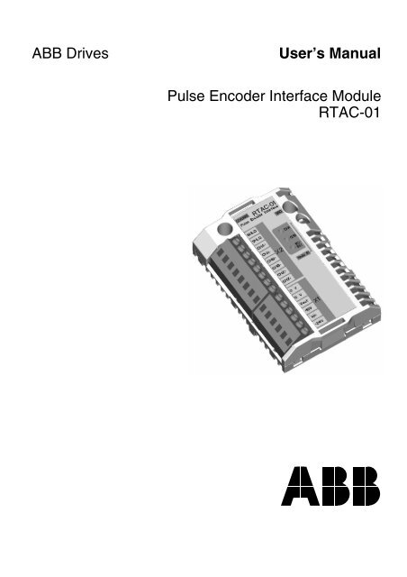
ABB Drives<br />
User’s <strong>Manual</strong><br />
Pulse Encoder Interface Module<br />
<strong>RTAC</strong>-<strong>01</strong>
Pulse Encoder Interface Module<br />
<strong>RTAC</strong>-<strong>01</strong><br />
User’s <strong>Manual</strong><br />
3AFE 64486853 REV A <strong>EN</strong><br />
EFFECTIVE: 1.5.2002<br />
© 2002 ABB Oy. All Rights Reserved.
Safety instructions<br />
Overview<br />
General safety<br />
instructions<br />
This chapter states the general safety instructions that<br />
must be followed when installing and operating the<br />
RAIO-<strong>01</strong> Analogue I/O Extension module.<br />
The material in this chapter must be studied before<br />
attempting any work on, or with, the unit.<br />
In addition to the safety instructions given below, read<br />
the complete safety instructions of the specific drive you<br />
are working on.<br />
WARNING! All electrical installation and maintenance<br />
work on the drive should be carried out by qualified<br />
electricians only.<br />
The drive and adjoining equipment must be properly<br />
earthed.<br />
Do not attempt any work on a powered drive. After<br />
switching off the mains, always allow the intermediate<br />
circuit capacitors 5 minutes to discharge before working<br />
on the frequency converter, the motor or the motor<br />
cable. It is good practice to check (with a voltage<br />
indicating instrument) that the drive is in fact discharged<br />
before beginning work.<br />
The motor cable terminals of the drive are at a<br />
dangerously high voltage when mains power is applied,<br />
regardless of motor operation.<br />
There can be dangerous voltages inside the drive from<br />
external control circuits even when the drive mains<br />
power is shut off. Exercise appropriate care when<br />
working on the unit. Neglecting these instructions can<br />
cause physical injury or death.<br />
<strong>RTAC</strong>-<strong>01</strong> User’s manual<br />
iii
Safety instructions<br />
iv<br />
<strong>RTAC</strong>-<strong>01</strong> User’s manual
Table of contents<br />
Safety instructions<br />
Overview . . . . . . . . . . . . . . . . . . . . . . . . . . . . . . . . . . . . . . . . . . . . . . . . . . . . . iii<br />
General safety instructions. . . . . . . . . . . . . . . . . . . . . . . . . . . . . . . . . . . . . . . . iii<br />
Table of contents<br />
Chapter 1 – Introduction<br />
Intended audience . . . . . . . . . . . . . . . . . . . . . . . . . . . . . . . . . . . . . . . . . . . . 1-1<br />
Before you start . . . . . . . . . . . . . . . . . . . . . . . . . . . . . . . . . . . . . . . . . . . . . . 1-1<br />
What this manual contains . . . . . . . . . . . . . . . . . . . . . . . . . . . . . . . . . . . . . . 1-2<br />
Chapter 2 – Overview<br />
Overview . . . . . . . . . . . . . . . . . . . . . . . . . . . . . . . . . . . . . . . . . . . . . . . . . . . 2-1<br />
The <strong>RTAC</strong>-<strong>01</strong> module . . . . . . . . . . . . . . . . . . . . . . . . . . . . . . . . . . . . . . . . . 2-1<br />
Module layout . . . . . . . . . . . . . . . . . . . . . . . . . . . . . . . . . . . . . . . . . . . . . . 2-1<br />
Delivery check . . . . . . . . . . . . . . . . . . . . . . . . . . . . . . . . . . . . . . . . . . . . . 2-2<br />
Compatibility . . . . . . . . . . . . . . . . . . . . . . . . . . . . . . . . . . . . . . . . . . . . . . . 2-2<br />
Warranty and liability information . . . . . . . . . . . . . . . . . . . . . . . . . . . . . . . 2-2<br />
Chapter 3 – Installation<br />
Mounting . . . . . . . . . . . . . . . . . . . . . . . . . . . . . . . . . . . . . . . . . . . . . . . . . . . 3-1<br />
Terminal designations . . . . . . . . . . . . . . . . . . . . . . . . . . . . . . . . . . . . . . . . . 3-2<br />
Power consumption . . . . . . . . . . . . . . . . . . . . . . . . . . . . . . . . . . . . . . . . . . . 3-3<br />
Encoder wiring . . . . . . . . . . . . . . . . . . . . . . . . . . . . . . . . . . . . . . . . . . . . . . . 3-5<br />
Phasing. . . . . . . . . . . . . . . . . . . . . . . . . . . . . . . . . . . . . . . . . . . . . . . . . . . 3-6<br />
Encoder output types . . . . . . . . . . . . . . . . . . . . . . . . . . . . . . . . . . . . . . . . 3-7<br />
Wiring diagrams . . . . . . . . . . . . . . . . . . . . . . . . . . . . . . . . . . . . . . . . . . . . 3-8<br />
Node address selection . . . . . . . . . . . . . . . . . . . . . . . . . . . . . . . . . . . . . . . 3-12<br />
Programming . . . . . . . . . . . . . . . . . . . . . . . . . . . . . . . . . . . . . . . . . . . . . . . 3-12<br />
<strong>RTAC</strong>-<strong>01</strong> User’s manual<br />
v
Table of contents<br />
Chapter 4 – Fault tracing<br />
Diagnostic LEDs . . . . . . . . . . . . . . . . . . . . . . . . . . . . . . . . . . . . . . . . . . . . . . 4-1<br />
Option slot installation . . . . . . . . . . . . . . . . . . . . . . . . . . . . . . . . . . . . . . 4-1<br />
I/O Module Adapter installation . . . . . . . . . . . . . . . . . . . . . . . . . . . . . . . 4-1<br />
Appendix A – Technical data<br />
vi<br />
<strong>RTAC</strong>-<strong>01</strong> User’s manual
Chapter 1 – Introduction<br />
Intended<br />
audience<br />
Before you start<br />
The manual is intended for the people who are<br />
responsible for commissioning and using an <strong>RTAC</strong>-<strong>01</strong><br />
Pulse Encoder Interface module with the ACS 800<br />
drive. The reader is expected to have a basic<br />
knowledge of electrical fundamentals, electrical wiring<br />
practices and how to operate the drive.<br />
It is assumed that the drive is installed and ready to<br />
operate before starting the installation of the extension<br />
module.<br />
In addition to conventional installation tools, have the<br />
drive manuals available during the installation as they<br />
contain important information not included in this<br />
manual. The drive manuals are referred to at various<br />
points of this document.<br />
<strong>RTAC</strong>-<strong>01</strong> User’s manual 1-1
Chapter 1 – Introduction<br />
What this manual<br />
contains<br />
This manual contains information on the wiring,<br />
configuration and use of the <strong>RTAC</strong>-<strong>01</strong> module.<br />
Safety instructions are featured in the first few pages<br />
of this manual.<br />
Chapter 2 – Overview contains a short description of<br />
the <strong>RTAC</strong>-<strong>01</strong> Pulse Encoder Interface module, a<br />
delivery checklist and warranty information.<br />
Chapter 3 – Installation contains instructions for<br />
module hardware settings, mounting and cabling.<br />
Chapter 4 – Fault tracing explains fault tracing and<br />
the LED indications of the <strong>RTAC</strong>-<strong>01</strong> module.<br />
Appendix A contains technical data.<br />
1-2 <strong>RTAC</strong>-<strong>01</strong> User’s manual
0<br />
8<br />
Chapter 2 – Overview<br />
Overview<br />
The <strong>RTAC</strong>-<strong>01</strong><br />
module<br />
This chapter contains a short description of the Pulse<br />
Encoder Interface module, a delivery checklist, and<br />
warranty information.<br />
The <strong>RTAC</strong>-<strong>01</strong> Pulse Encoder Interface module offers an<br />
interface for a digital pulse encoder connection. A pulse<br />
encoder should be used if accurate speed or position<br />
(angle) feedback from the motor shaft is required.<br />
Module layout<br />
Node ID selector (S1)<br />
2<br />
4<br />
6<br />
Fixing screw (GND)<br />
Diagnostic LEDs<br />
1<br />
3<br />
5<br />
CHASSIS<br />
<strong>RTAC</strong>-<strong>01</strong><br />
PULSE <strong>EN</strong>CODER INTERFACE<br />
GND<br />
SHLD<br />
F<br />
E<br />
D<br />
C<br />
B<br />
7<br />
A<br />
9<br />
SHLD<br />
CHA<br />
CHA+<br />
CHB<br />
WD/<br />
INIT<br />
X2<br />
NODE ID<br />
CHA-<br />
CHB+<br />
CHB-<br />
CHZ+<br />
CHZ-<br />
0 V<br />
0 V<br />
X1<br />
V OUT<br />
+15V<br />
V IN<br />
+24V<br />
Fixing screw<br />
(CHASSIS)<br />
Terminal block for<br />
encoder signals (X2)<br />
Terminal block for encoder<br />
power connections (X1)<br />
1 2 3 4 5 6 7 8 1 2 3 4 5 6<br />
<strong>RTAC</strong>-<strong>01</strong> User’s manual 2-1
Chapter 2 – Overview<br />
Delivery check<br />
Compatibility<br />
Warranty and<br />
liability<br />
information<br />
The option package contains:<br />
• <strong>RTAC</strong>-<strong>01</strong> module<br />
• Encoder supply voltage selection jumper<br />
• Two screws (M3×8 mm)<br />
• This manual.<br />
The <strong>RTAC</strong>-<strong>01</strong> is compatible with ACS 800 Standard<br />
Application Program version ASXR7000 or later.<br />
The warranty for your ABB drive and options covers<br />
manufacturing defects. The manufacturer carries no<br />
responsibility for damage due to transport or unpacking.<br />
In no event and under no circumstances shall the<br />
manufacturer be liable for damages and failures due to<br />
misuse, abuse, improper installation, or abnormal<br />
conditions of temperature, dust, or corrosives, or<br />
failures due to operation above rated capacities. Nor<br />
shall the manufacturer ever be liable for consequential<br />
and incidental damages.<br />
The period of manufacturer's warranty is 12 months,<br />
and not more than 18 months, from the date of delivery.<br />
Extended warranty may be available with certified startup.<br />
Contact your local distributor for details.<br />
Your local ABB Drives company or distributor may have<br />
a different warranty period, which is specified in their<br />
sales terms, conditions, and warranty terms.<br />
If you have any questions concerning your ABB drive,<br />
contact your local distributor or ABB Drives office.<br />
The technical data and specifications are valid at the<br />
time of printing. ABB reserves the right to subsequent<br />
alterations.<br />
2-2 <strong>RTAC</strong>-<strong>01</strong> User’s manual
Chapter 3 – Installation<br />
WARNING! Follow the safety instructions given in this<br />
guide and in the ACS 800 Hardware <strong>Manual</strong>.<br />
Mounting<br />
The <strong>RTAC</strong>-<strong>01</strong> is to be inserted into the position marked<br />
SLOT 1 or SLOT 2 on the drive. The module is held in<br />
place with plastic retaining clips and two screws. The<br />
screws also provide the earthing of the I/O cable shield<br />
connected to the module, and interconnect the GND<br />
signals of the module and the RMIO board.<br />
On installation of the module, the signal and power<br />
connection to the drive is automatically made through a<br />
38-pin connector.<br />
The module can alternatively be mounted on a DIN railmountable<br />
AIMA-<strong>01</strong> I/O Module Adapter (not available<br />
at the time of publication).<br />
Mounting procedure:<br />
1. Insert the module carefully into SLOT 1 or SLOT 2<br />
on the RMIO board until the retaining clips lock the<br />
module into position.<br />
2. Fasten the two screws (included) to the stand-offs.<br />
Note: Correct installation of the screws is essential for<br />
fulfilling the EMC requirements and for proper operation<br />
of the module.<br />
<strong>RTAC</strong>-<strong>01</strong> User’s manual 3-1
Chapter 3 – Installation<br />
Terminal<br />
designations<br />
X1 Marking Description<br />
1<br />
2<br />
0 V<br />
0 V<br />
Encoder power supply, either 15 or 24 V DC (according<br />
to jumper selection on terminals 4, 5 and 6).<br />
(0 V is also used with single-ended encoder connection<br />
3 V OUT<br />
for balancing the A+, B+ and/or Z+ conductors. See<br />
Figures 3-3 to 3-6.)<br />
4<br />
5<br />
+15V<br />
V IN<br />
Encoder supply voltage selection:<br />
Terminals 4 and 5 connected: 15 V (default)<br />
Terminals 5 and 6 connected: 24 V<br />
6 +24V<br />
(Jumper is supplied with the <strong>RTAC</strong> module)<br />
Max. 5 watts (see Power consumption below)<br />
Connected internally on the circuit board.<br />
X2 Marking Description<br />
1 SHLD<br />
2 SHLD<br />
Shield<br />
For earthing of the encoder cable shields. Internally<br />
connected to the frame.<br />
3<br />
4<br />
A+<br />
A-<br />
A<br />
A<br />
• Max. signal frequency: 200 kHz<br />
• Signal levels:<br />
“1” > 7.6 V, “0” < 5 V (for 15 V supply)<br />
5 B+ B<br />
“1” > 12.2 V, “0” < 8 V (for 24 V supply)<br />
• Input channels isolated from the logic, power supply,<br />
6 B- B<br />
and earth<br />
• When the drive runs in the Forward direction,<br />
7 Z+ Z channel A should lead channel B by 90° (electrical)<br />
8 Z- Z<br />
• Channel Z: One pulse per revolution (used in<br />
positioning applications only)<br />
3-2 <strong>RTAC</strong>-<strong>01</strong> User’s manual
Chapter 3 – Installation<br />
Power<br />
consumption<br />
Without an external power supply, the <strong>RTAC</strong>-<strong>01</strong> can<br />
supply 5 W (at either 15 V or 24 V DC) to the encoder.<br />
For higher power, an external power supply is required.<br />
As the power consumption of the module depends on<br />
many factors (e.g. max. speed of the motor, encoder<br />
pulse number per revolution, encoder cable length and<br />
leakage capacitance), it should be checked on each<br />
occasion if an external power supply is needed. See the<br />
encoder documentation for details. Figure 3-2 shows<br />
the approximate power consumption of an encoder with<br />
differential outputs, based on actual measurements.<br />
The external power supply should be connected as<br />
shown below.<br />
Note: With an external power supply, the voltage<br />
selection jumper should be removed from X1.<br />
<strong>RTAC</strong><br />
X1<br />
0V<br />
1<br />
0 V<br />
2<br />
0 V<br />
V cc<br />
0V<br />
V cc<br />
3<br />
4<br />
V OUT<br />
+15V<br />
5<br />
V IN<br />
6<br />
+24V<br />
X2<br />
2<br />
SHLD<br />
Figure 3-1 External power supply connection diagram<br />
<strong>RTAC</strong>-<strong>01</strong> User’s manual 3-3
Chapter 3 – Installation<br />
Encoder power<br />
consumption<br />
P idle + 2.0 W<br />
Cable length<br />
300 m<br />
P idle + 1.75 W<br />
P idle + 1.5 W<br />
150 m<br />
P idle + 1.25 W<br />
100 m<br />
P idle + 1.0 W<br />
P idle + 0.75 W<br />
P idle + 0.5 W<br />
P idle + 0.25 W<br />
20 m<br />
P idle<br />
EPN = 1024 ppr:<br />
EPN = 2048 ppr:<br />
EPN = 512 ppr:<br />
0 300 600 900 1200 1500 1800 2100 2400 2700 3000<br />
0 150 300 450 600 750 900 1050 1200 1350 1500<br />
0 600 1200 1800 2400 3000 3600 4200 4800 5400 6000<br />
Motor<br />
speed<br />
(rpm)<br />
EPN = Encoder pulse number<br />
P idle = Encoder power consumption when idle. See encoder documentation.<br />
Figure 3-2 Approximate power consumption of an encoder for four different<br />
cable lengths. The chart is based on a measurement with a 24 V DC, 1024 ppr<br />
pulse encoder with differential outputs coupled to a motor shaft rotating at 1500<br />
rpm.<br />
3-4 <strong>RTAC</strong>-<strong>01</strong> User’s manual
Chapter 3 – Installation<br />
Encoder wiring<br />
The pulse encoder should be connected to the <strong>RTAC</strong><br />
module with a cable specified below.<br />
Cable<br />
construction<br />
Conductor crosssectional<br />
area<br />
Maximum cable length<br />
4 × (2+1) Twisted pair cable with individual<br />
and overall shields.<br />
0.5 to 1.0 mm 2<br />
Dependent on encoder output type as follows:<br />
300 m (differential push-pull)<br />
200 m (single-ended push-pull)<br />
100 m (open collector or emitter)<br />
Either a single-ended or differential connection can be<br />
used, but the manufacturer’s recommendations should<br />
be taken into account. Starting on page 3-8, there are<br />
wiring diagrams for different encoder output types.<br />
Compare encoder documentation and the diagrams<br />
below to determine the output type.<br />
Note: The cable shields should be earthed at the <strong>RTAC</strong><br />
module only if the encoder is not isolated from the<br />
motor and earth. However, if the encoder is isolated<br />
from the motor and earth, the cable shields are to be<br />
connected to the encoder housing also.<br />
Note: Do not route the encoder cables parallel to power<br />
(eg. motor) cables.<br />
<strong>RTAC</strong>-<strong>01</strong> User’s manual 3-5
Chapter 3 – Installation<br />
Phasing<br />
When the encoder is connected correctly, running the<br />
drive in the Forward (positive speed reference) direction<br />
should produce a positive encoder speed feedback.<br />
On incremental encoders, the two output channels,<br />
usually marked 1 and 2 or A and B, are 90° (electrical)<br />
apart from each other. When rotated clockwise, most<br />
encoders – but not all – have channel 1 leading channel<br />
2 as illustrated below. Determine the leading channel by<br />
referring to the encoder documentation or by measuring<br />
with an oscilloscope.<br />
A or 1<br />
A or 1<br />
B or 2<br />
B or 2<br />
Z or 0<br />
Z or 0<br />
The encoder output channel that leads when the drive<br />
runs Forward should be connected to <strong>RTAC</strong> input A, the<br />
output channel that trails to <strong>RTAC</strong> input B.<br />
The zero reference output channel (usually marked 0, N<br />
or Z) needs to be connected in positioning applications<br />
only.<br />
3-6 <strong>RTAC</strong>-<strong>01</strong> User’s manual
Chapter 3 – Installation<br />
Encoder output<br />
types<br />
The diagram presents some typical encoder output<br />
types. The following pages include wiring diagrams for<br />
each output type.<br />
Push-pull<br />
Open collector<br />
(Sinking)<br />
Open emitter<br />
(Sourcing)<br />
V CC<br />
OUT<br />
V CC<br />
R L1<br />
R L2<br />
V CC<br />
OUT<br />
V CC<br />
R L<br />
V CC<br />
OUT<br />
R L<br />
V CC = Encoder input power supply voltage<br />
R L = Load resistor at encoder output channel<br />
<strong>RTAC</strong>-<strong>01</strong> User’s manual 3-7
Chapter 3 – Installation<br />
Wiring diagrams<br />
Encoder output type: Push-pull<br />
Output pulse order in Forward rotation: 1, 2<br />
(With encoders with 2 as the leading output,<br />
1 and 2 should be wired to <strong>RTAC</strong> terminals B+ and A+ respectively.<br />
1 and 2 should be wired to <strong>RTAC</strong> terminals B- and A- respectively.)<br />
Differential connection<br />
1<br />
2<br />
<strong>RTAC</strong><br />
X2<br />
VCC<br />
0V<br />
1<br />
1<br />
2<br />
2<br />
0<br />
0<br />
1<br />
2<br />
3<br />
4<br />
5<br />
6<br />
7<br />
8<br />
SHLD<br />
SHLD<br />
A+<br />
A-<br />
B+<br />
B-<br />
Z+<br />
Z-<br />
X1<br />
Encoder supply<br />
voltage selection<br />
(15 or 24 V)<br />
24V<br />
15V<br />
1<br />
2<br />
3<br />
4<br />
5<br />
6<br />
0 V<br />
0 V<br />
V OUT<br />
+15V<br />
V IN<br />
+24V<br />
Figure 3-3 Differential wiring of pulse encoders with push-pull outputs<br />
3-8 <strong>RTAC</strong>-<strong>01</strong> User’s manual
Chapter 3 – Installation<br />
Single-ended connection<br />
Encoder output type: Push-pull<br />
Output pulse order in Forward rotation: 1, 2<br />
1<br />
2<br />
(With encoders with 2 as the leading output,<br />
1 and 2 should be wired to <strong>RTAC</strong> terminals B+ and A+ respectively.<br />
1 and 2 should be wired to <strong>RTAC</strong> terminals B- and A- respectively.)<br />
<strong>RTAC</strong><br />
X2<br />
VCC<br />
0V<br />
1<br />
2<br />
0<br />
1<br />
2<br />
3<br />
4<br />
5<br />
6<br />
7<br />
8<br />
SHLD<br />
SHLD<br />
A+<br />
A-<br />
B+<br />
B-<br />
Z+<br />
Z-<br />
X1<br />
Encoder supply<br />
voltage selection<br />
(15 or 24 V)<br />
24V<br />
15V<br />
1<br />
2<br />
3<br />
4<br />
5<br />
6<br />
0 V<br />
0 V<br />
V OUT<br />
+15V<br />
V IN<br />
+24V<br />
Figure 3-4 Single-ended wiring of pulse encoders with push-pull outputs<br />
<strong>RTAC</strong>-<strong>01</strong> User’s manual 3-9
Chapter 3 – Installation<br />
Encoder output type: Open collector (Sinking)<br />
Output pulse order in Forward rotation: 1, 2<br />
1<br />
2<br />
(With encoders with 2 as the leading output,<br />
1 and 2 should be wired to <strong>RTAC</strong> terminals B+ and A+ respectively)<br />
<strong>RTAC</strong><br />
X2<br />
VCC<br />
0V<br />
1<br />
2<br />
0<br />
1<br />
2<br />
3<br />
4<br />
5<br />
6<br />
7<br />
8<br />
SHLD<br />
SHLD<br />
A+<br />
A-<br />
B+<br />
B-<br />
Z+<br />
Z-<br />
24V: 1.8…2.2 kΩ<br />
15V: 1.0…1.5 kΩ<br />
0.5 W<br />
X1<br />
Encoder supply<br />
voltage selection<br />
(15 or 24 V)<br />
24V<br />
15V<br />
1<br />
2<br />
3<br />
4<br />
5<br />
6<br />
0 V<br />
0 V<br />
V OUT<br />
+15V<br />
V IN<br />
+24V<br />
Figure 3-5 Wiring of pulse encoders with open collector (sinking) outputs.<br />
3-10 <strong>RTAC</strong>-<strong>01</strong> User’s manual
Chapter 3 – Installation<br />
Encoder output type: Open emitter (Sourcing)<br />
Output pulse order in Forward rotation: 1, 2<br />
1<br />
2<br />
(With encoders with 2 as the leading output,<br />
1 and 2 should be wired to <strong>RTAC</strong> terminals B+ and A+ respectively)<br />
<strong>RTAC</strong><br />
X2<br />
VCC<br />
0V<br />
1<br />
2<br />
0<br />
1<br />
2<br />
3<br />
4<br />
5<br />
6<br />
7<br />
8<br />
SHLD<br />
SHLD<br />
A+<br />
A-<br />
B+<br />
B-<br />
Z+<br />
Z-<br />
24V: 1.8…2.2 kΩ<br />
15V: 1.0…1.5 kΩ<br />
0.5 W<br />
X1<br />
Encoder supply<br />
voltage selection<br />
(15 or 24 V)<br />
24V<br />
15V<br />
1<br />
2<br />
3<br />
4<br />
5<br />
6<br />
0 V<br />
0 V<br />
V OUT<br />
+15V<br />
V IN<br />
+24V<br />
Figure 3-6 Wiring of pulse encoders with open emitter (sourcing) outputs.<br />
<strong>RTAC</strong>-<strong>01</strong> User’s manual 3-11
Chapter 3 – Installation<br />
Node address<br />
selection<br />
Programming<br />
If the <strong>RTAC</strong>-<strong>01</strong> module is mounted onto external I/O<br />
Module Adapter AIMA-<strong>01</strong>, choose the proper node ID<br />
for the module using the node ID selector (S1).<br />
The settings 0…F correspond to node IDs 16…31. The<br />
default setting is 0 (node ID 16).<br />
Setting the node ID is not required when the module is<br />
mounted into SLOT 1 or SLOT 2 on the drive.<br />
The <strong>RTAC</strong>-<strong>01</strong> is programmed through drive parameters.<br />
These parameters must be checked and adjusted. For<br />
further information, see the drive Firmware <strong>Manual</strong>,<br />
Parameter Groups 50 and 98.<br />
3-12 <strong>RTAC</strong>-<strong>01</strong> User’s manual
Chapter 4 – Fault tracing<br />
Diagnostic LEDs<br />
Option slot<br />
installation<br />
I/O Module Adapter<br />
installation<br />
There are three diagnostic LEDs on the <strong>RTAC</strong>-<strong>01</strong><br />
module. The CHA (green) and CHB (green) LEDs show<br />
the activity on channels A and B. The WD/INIT (yellow)<br />
LED shows the status of the module.<br />
WD/INIT is lit when the drive is configuring the module<br />
at power-up.<br />
In case the LED does not go out after one second:<br />
• The configuration has failed.<br />
- Cycle the power supply of the drive.<br />
• The module has a hardware failure.<br />
- Ensure the 38-pin connector is properly inserted.<br />
- Contact an ABB service representative.<br />
• There is no communication with the drive.<br />
- Check that the drive is powered.<br />
- Check the module node ID.<br />
- Check that the fibre optic cables are connected<br />
correctly (transmitters to receivers) and the<br />
connectors properly inserted.<br />
- Check the fibre optic cables visually for dirt or<br />
flaws.<br />
- Ensure the 38-pin connector is properly inserted.<br />
- Try new fibre optic cables.<br />
- Contact an ABB service representative.<br />
<strong>RTAC</strong>-<strong>01</strong> User’s manual 4-1
Chapter 4 – Fault tracing<br />
4-2 <strong>RTAC</strong>-<strong>01</strong> User’s manual
C<br />
4<br />
Appendix A – Technical data<br />
Dimensions:<br />
34 mm<br />
CHASSIS<br />
<strong>RTAC</strong>-<strong>01</strong><br />
PULSE <strong>EN</strong>CODER INTERFACE<br />
GND<br />
95 mm<br />
1 2 3 4 5 6 7 8 1 2 3 4 5 6<br />
SHLD<br />
SHLD<br />
CHA+<br />
CHA-<br />
CHB+<br />
CHB-<br />
CHZ+<br />
CHZ-<br />
0 V<br />
0 V<br />
V OUT<br />
+15V<br />
V IN<br />
+24V<br />
X2<br />
X1<br />
CHA<br />
CHB<br />
WD/<br />
INIT<br />
NODE ID<br />
B<br />
E<br />
D<br />
A<br />
9<br />
F<br />
0<br />
8<br />
1<br />
7<br />
2<br />
3<br />
5<br />
6<br />
20<br />
mm<br />
62 mm<br />
Mounting: Into an option slot of the RMIO board of the<br />
drive or onto external I/O Module Adapter (AIMA-<strong>01</strong>).<br />
Degree of protection: IP 20<br />
Ambient conditions: The applicable ambient<br />
conditions specified for the drive in its Hardware <strong>Manual</strong><br />
are in effect.<br />
Hardware settings:<br />
• Rotary switch for node ID selection (range 16…31)<br />
Connectors:<br />
• 38-pin parallel bus connector<br />
• Two (one 6-pole, one 8-pole) non-detachable screwtype<br />
terminal blocks for max. 2.5 mm 2 wire.<br />
<strong>RTAC</strong>-<strong>01</strong> User’s manual A-1
Appendix A – Technical data<br />
Encoder interface:<br />
• CH A, CH B, CH Z, differential or single-ended<br />
• Output voltage 1: +24 V DC ±10%, 5 W max., shortcircuit<br />
proof<br />
• Output voltage 2: +15 V DC ±10%, 5 W max., shortcircuit<br />
proof<br />
• Signal levels:<br />
"1" >7.6 V, "0" < 5 V (for 15 V supply)<br />
"1" >12.2 V, "0" < 8 V (for 24 V supply)<br />
• Frequency: 200 kHz (max.)<br />
• Speed feedback resolution: 0.00305% (15 bits)<br />
• Speed feedback accuracy: 50 ppm<br />
• Maximum encoder cable length:<br />
- 300 m (differential push-pull)<br />
- 200 m (single-ended push-pull)<br />
- 100 m (open collector or emitter)<br />
• Isolated from the logic and earth. Test voltage:<br />
1.5 kV AC, 1 minute<br />
General<br />
• Max. power consumption:<br />
140 mA (5 V) + 55 mA (24 V)<br />
• Estimated min. lifetime: 100 000 h<br />
• All materials UL/CSA-approved<br />
• Complies with EMC standards <strong>EN</strong> 50081-2 and<br />
<strong>EN</strong> 50082-2<br />
A-2 <strong>RTAC</strong>-<strong>01</strong> User’s manual
<strong>RTAC</strong>-<strong>01</strong><br />
3AFE 64486853 REV A <strong>EN</strong><br />
EFFECTIVE: 1.5.2002<br />
ABB Oy<br />
AC Drives<br />
P.O. Box 184<br />
FIN-00381 Helsinki<br />
FINLAND<br />
Telephone:+358 10 222 000<br />
Fax: +358 10 222 2681<br />
Internet: www.abb.com<br />
ABB Inc.<br />
Drives & Power Products<br />
16250 West Glendale Drive<br />
New Berlin, WI 53151<br />
USA<br />
Telephone:262 785-8378<br />
800 243-4384<br />
Fax: 262 780-5135