here - Traplet Publications
here - Traplet Publications
here - Traplet Publications

You also want an ePaper? Increase the reach of your titles
YUMPU automatically turns print PDFs into web optimized ePapers that Google loves.
£Ia GREAT BRITAIN<br />
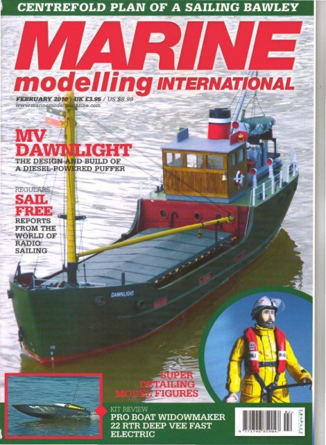
MV DAWNLIGHT<br />
TOM GORMAN DESCRIBES HIS BUILD OF A DIESEL-POWERED PUFFER<br />
AU'nfOR: TOM GORMAN<br />
THE DESIGN<br />
I first saw the ship 'Raylight' in an article by James Pottinger in<br />
the magazine 'Model Shipwright' although I believe that was an<br />
expanded repeat of an earlier article published in Model Boats<br />
magazine in 1966. The idea of a traditional puffer but diesel engine<br />
driven appealed to me. I brought my thoughts to Bryan Ward of<br />
Mobile Marine Models and we agreed that if the drawings were<br />
enlarged to a scale of 1:32 it would be an ideal model to add to his<br />
current range of similarly scaled tugs, lighters etc. Consequently<br />
I agreed to build a suitable hull of the model in timber to a quality<br />
suitable for using as a plug for hulls in fibreglass and to build<br />
a complete model upon the GRP hull to prove the build and<br />
provide templates and data to be used to build up a complete<br />
set of kit masters. The drawing when expanded and examined,<br />
showed certain'areas w<strong>here</strong> alterations were needed to permit<br />
easy manufacture of parts for making up a kit, the drawing was<br />
then altered to suit and the model was re-named 'Dawnliqht'. Mr<br />
Pottinger kindly gave his permission for the use of the drawings in<br />
this case.<br />
The photographs show the basic build up of the hull, which is the<br />
standard plank-on-frame type but with bulkheads in place of frames.<br />
Decks were inserted before the hull was sheathed in 3.0 mm thick<br />
ply to ensure that the hull would not twist and to add strength. The<br />
timber plug needs to stand up to a fair degree of pressure when<br />
it is covered in resin and glass cloth as the material gets very hot<br />
when it cures and it shrinks over the plug in the process creating a<br />
high pressure on the timber. Once the timber hull was finished the<br />
surface was brought to a fine degree of smoothness, it needed to<br />
be brought up to the finish required for reproduction.<br />
The details such as relief ports, anchor pockets, portholes, rope<br />
guides and bilge keels need to be shown so that all future hulls in<br />
GRP will carry this detail to allow the modeller to complete his/her<br />
model correctly; obviously adding such detail in relief needs careful<br />
measurement to ensure each item is in its precise location. This<br />
detail work can be time consuming.<br />
THE HULL<br />
I was advised that it would take approximately three weeks<br />
between delivery of the plug to the supply of the first GRP hull<br />
and this led me to the calculation of costing. The plug had taken<br />
almost 80 man hours to build; the master mould would need about<br />
a further 30 hours minimum and then the building of the model<br />
at about 350 hours all add up to a substantial amount of time not<br />
counting the cost of materials etc. Some twenty-five or more years<br />
ago I calculated that my initial development costs for a model<br />
ship kit were in the order of £3,000; today this must now reach in<br />
excess of £5,000 and a manufacturer needs to sell a great many<br />
kits to cover such costs before he/she can start to make a profit. It<br />
makes one to think does it not?<br />
The first hull from the mould eventually arrived and work could<br />
commence upon the Quilding of the motor puffer. The hull was<br />
first washed in warm water and detergent to remove any traces<br />
of the release agent used in manufacture, such release agent<br />
would prevent the primer and finishing paints from firmly adhering<br />
to the hull. Next all the marked release ports, portholes and rope<br />
guide locations were covered with masking tape before they were<br />
drilled out and opened up to the correct size. Masking tape was<br />
used to prevent the drills from wandering and to prevent the fine<br />
gel coat outer surface of the hull from being damaged as the work<br />
proceeded, Once all these areas had been completed; the hull was<br />
54 FEBRUARY 2010 www.marinemodelmagazine.com
abraded lightly allover using 600 grit wet and dry abrasive, used<br />
wet and the hull was rinsed and left to dry naturally. Rubbing the<br />
hull all over with fine abrasive provides a key for the subsequent<br />
application of primer and finish coatings.<br />
RUNNING<br />
GEAR<br />
At this point the propeller shaft, 8.0 inches long was inserted<br />
through a suitable hole drilled and opened up to suit the outer tube<br />
of the shaft. Using a Protoline unit from Mobile Marine Models, the<br />
shaft and motor were set into the hull. A mounting for the motor<br />
being made from 6.0 mm thick plywood and prepared to accept<br />
the motor, this process allowing of accurately aligning the motor,<br />
coupling and shaft. Forward of the motor a small platform of 3.0<br />
mm plywood mounted on two blocks of soft wood was installed to<br />
carry the M.troniks speed controller and the on/off switch for the<br />
electrics. Further forward a cradle of plywood was made to hold the<br />
6.0 volt 10 amp/hr battery lying on its side. All such plywood parts<br />
were treated to two or three coats of paint once they were glued<br />
down. Note that the 8" shaft, motor, coupling, ESC platform and<br />
battery tray were all located so that they could be easily accessed<br />
through the hatch opening. Motor, coupling, ESC and battery were<br />
all removed after test fitting to allow the hull to be painted.<br />
Before proceeding to paint the hull the cast portholes and rope<br />
guides were next prepared for fixing, the inside of the hull was<br />
lightly abraded in way of all these locations and strips of 0.5 mm<br />
thick styrene sheet was attached using a contact adhesive. At the<br />
bow area this covered the inside of the bulwarks and allowed easy<br />
attachment of bulwark supports cut from styrene and the top rails<br />
that were also made from styrene sheet. The cast portholes and<br />
the oval rope gUides from the Mobile Marine Models range were<br />
next carefully fitted and glued into place with superglue.<br />
Main deck supports were made from strips of 3.0 mm thick x 10.0<br />
mm wide soft wood and tacked with superglue along the sides of<br />
the hull below the freeing ports at a depth to allow the main decks<br />
of 3.0 mm plywood to be fitted flush with the bottom of each port.<br />
A second strip being glued over the first to give a thickness of<br />
6.0 mm for mounting the decks, once in place they were secured<br />
with catalysed resin for extra security. All the holes in the hull were<br />
covered on the inside with masking tape to prevent the spray of<br />
paint from spoiling the hull interior. To ensure that no grease or<br />
finger marks were left to mar the paint finish the hull was wiped<br />
over with methylated spirit and allowed to dry.<br />
The whole hull was next treated to three coats of red oxide primer<br />
from spray cans, each coating being carefully examined and any<br />
imperfections remedied before the next was applied. The paints<br />
used to cover the hull were all from Halfords and were of their<br />
acrylic car finishes. The hull was then left to harden over a period<br />
of four days before it was stood carefully on a flat surface and<br />
braced to bring the waterline parallel to the surface of the table.<br />
The waterline was marked off with a soft pencil attached to a large<br />
try square drawn carefully round the hull. Accurate measurements<br />
being needed <strong>here</strong> and all measurements carried out on the basis<br />
of 'measure twice, act once'.<br />
The lower part of the hull was covered completely with tinder dry<br />
newsprint held in place with masking tape; tinder dry to prevent<br />
any chance of newsprint marring the paint surface. The upper hull<br />
ABOVE: Timber beams across the GRP hull ABOVE: Midships decks laid over beams, ABOVE: Bulkhead aft of midships deck<br />
to cerry midships deck beams to be cut away<br />
www.marinemodelmagazine.com FEBRUARY 2010 55
ABOVE: Stern of hull showing propeller<br />
and rudder, lower support for rudder stock<br />
still to be fitted<br />
ABOVE: Supports for motor and speed<br />
control unit in place<br />
ABOVE:<br />
Beams to carry radio receiver and<br />
base for 6 volt f 0 amp/hr battery in hull<br />
ABOVE: Tray carrying rudder servo fixed to<br />
beams in stern area of hull<br />
ABOVE: Battery pack and switch for<br />
navigation lights under after deck with<br />
modified tray and with rudder servo in place<br />
ABOVE: Centre of hull showing motor,<br />
speed control, switch and battery in place<br />
was then spray painted green, four coats being applied and each<br />
examined carefully as it dried. Technically the hull colour should<br />
have been black but this would not have been as attractive as a<br />
fine lighter colour and green (Ford Laurel Green) was chosen as it<br />
was to hand in the workshop. At this point the hull was set aside<br />
for almost two weeks to cure fully before further work was done<br />
and the main deck hatch was built in the interim. This hatch is a<br />
prominent part of the model and had to be researched and made as<br />
accurately<br />
as possible.<br />
THE HATCHES<br />
The full size hatches of such vessels in the years before and after<br />
the Second World War had covers that were formed from steel or<br />
wrought iron girders laid over the opening and intC! guides on either<br />
side of the opening. These girders were used to hold hatch boards<br />
of heavy timber and approximately six feet x two feet in size. Over<br />
these boards were then fitted tarpaulin sheets secured round the<br />
perimeter of the hatch with steel bars laid in side mounted brackets<br />
and made tight with wooden wedges driven hard in place. Thinner<br />
ABOVE: Forward end of hull showing radio receiver and battery<br />
mounted<br />
steel bars were fitted across the tarpaulin to prevent it moving and<br />
such bars were locked in place with bolts and nuts.<br />
The model hatch was made from a frame of 3.0 mm thick<br />
plywood approximately 25 mm wide stood on edge and glued<br />
into a rectangle with a raised centre at each end. The rectangle<br />
was braced at each corner with triangles of 3.0 mm plywood. The<br />
top was formed from two pieces of 1.5 mm plywood over three<br />
fine braces across the hatch. The outer faces of this hatch were<br />
covered with 0.5 mm styrene sheet glued down with contact<br />
adhesive. Round the sides and ends of the structure were glued<br />
fine styrene angle to simulate the perimeter rails and the whole of<br />
the top surface of the hatch was covered with fine cotton sail cloth<br />
glued down with diluted PVA adhesive.<br />
Once the glue had dried the cloth was painted with dark green<br />
paint mixed from water based acrylic artists medium and set aside<br />
to dry. The sides of the hatch were painted black and finally over<br />
40 tiny wooden wedges were cut and glued round the hatch sides<br />
to simulate the correct finish. Strips of styrene painted black<br />
were glued in place over the hatch top as illustrated. This hatch<br />
consumed almost 25 hours of work and experimentation.<br />
Cross beams cut from 6.0 mm thick x 10 mm wide plywood were<br />
glued across<br />
the well of the hull to carry the main deck, these beams<br />
were fitted with small triangles of plywood at each corner to provide<br />
extra security. The main decks of 3.0 mm plywood were next cut to<br />
fit, templates of card being made first to ensure accurate fitting of the<br />
decks, this section of decks being made in two halves to allow easy<br />
attachment. Once tried in place and fit found correct the underside<br />
of both parts were treated to two coats of white primer to render<br />
the timber waterproof. 'They were then glued carefully in place using<br />
PVA thixotropic adhesive. Once this deck was complete, 0.5 mm<br />
thick styrene was cut to fit the inside of the bulwarks and fixed in<br />
place with contact cement. The relief ports were then cut through the<br />
styrene and bulwark supports cut from 1.0 mm thick styrene were<br />
glued in place with liquid poly. The athwartship beams in the way of<br />
the hatch opening<br />
were next cut away and strips of 3.0 mm ply cut to<br />
fit were glued under the edges of the opening<br />
thick area to which to attach the coamings.<br />
to fonm a reasonably<br />
56 FEBRUARY 2010 www.marinemodelmagazine.com
Coamings made from strips of 3.0 mm thick ply approximately 15<br />
mm wide were made to fit round the hatch opening, measurement<br />
of this opening and the fit of the coamings was critical as the premade<br />
hatch had to be a sliding fit after all parts had been painted.<br />
The coamings were reinforced at each corner with triangles of 3.0<br />
mm thick ply and they were painted by brush with acrylics mixed<br />
to a dull red. The hatch was tried in place and found to fit; it gave<br />
a large opening, when removed, allowing easy access to the radio<br />
equipment, motor, speed controller and switches etc.<br />
Progressively the remainder of the decks were made from 3.0 mm<br />
plywood and fitted in place over suitable beams. It was found that<br />
the fibreglass hull had spread slightly and a pair of long, adjustable<br />
clamps was used to hold the hull sides until the beams and glue<br />
were firmly fixed. All the decks were treated with two coats of<br />
sanding sealer and sanded smooth once fitted. The after deck was<br />
cut away in way of the superstructure and low coamings were fitted<br />
made from strips of 3.0 mm plywood. Beneath this area a platform<br />
was made from 3.0 mm plywood over the propeller shaft and on<br />
this was fitted a battery pack of four 1.2 mmM cells to feed the<br />
navigation lights and a suitable on/off switch was also fitted <strong>here</strong>, in<br />
circuit with the battery pack and lighting harness.<br />
SUPERSTRUCTURE<br />
The superstructure was built from 1.5 mm plywood to fit<br />
accurately over the coamings and was of a simple box construction<br />
except for the wheelhouse. So frequently, when fitting glaZing, glue<br />
spreads and mars the clear material. On this occasion I decided<br />
to build the wheelhouse walls in three layers to allow glazing to<br />
slide into place, glue free, and to be held securely when the roof<br />
was glued on. The inner and outer walls were cut to show the full<br />
size of the window apertures. the middle section of the walls was<br />
cut smaller than the outer and inner sections by enough to allow<br />
the glazing to slide between the outer sections. All three individual<br />
wall sections were then glued firmly together and prepared for<br />
staining and varnishing before being assembled. The result can be<br />
seen in the photographs<br />
ABOVE: Stern view showing construction of aft superstructure<br />
Inside the wheelhouse were fitted, a wheel on a stand and complete<br />
with chain and pulley, binnacle and telegraph, all from the Mobile<br />
Marine Models range and a chart table complete with chart was<br />
made and.fitted to the port side of the wheelhouse.<br />
The funnel was carved and sanded from a block of jelutong to<br />
match the drawings. The wheelhouse roof was prepared next.<br />
painted and fitted with navigation lamps and casings, the lamps of<br />
LED's, from Mobile Marine Models, were fitted and white styrene<br />
tubes were added beneath the lamps to conceal the cables that led<br />
through the wheelhouse. The wheelhouse doors were fitted with<br />
small brass hinges purchased from Squires. and can be opened or<br />
closed as required. Aft of the funnel housing are two water tanks<br />
and a skylight and further aft is the quadrant over the rudder with<br />
operating chains in place. Tubes for the rudder operating units run<br />
on either side of the engine room casing. Above the aft tanks etc.,<br />
are two frames upon which the lifeboat is mounted and a small<br />
ABOVE: View inside wheelhouse showing wheel, steering chain<br />
with gypsy and telegraph<br />
ABOVE: Stern end of superstructure<br />
base illustrating rudder quadrant with<br />
steering chain<br />
ABOVE: Main mast lower showing pivot<br />
arrangement<br />
for derrick<br />
ABOVE:<br />
slewing<br />
Base of main mast illustrating<br />
winch<br />
www.rnarinernodelmagazine.com FEBRUARY 2010 57
ABOVE: Stern deck of model completed<br />
ABOVE: Stern of model illustrating wheelhouse<br />
and detail<br />
ABOVE: Detail photo to show hatch with tarpaulin and straps etc.<br />
derrick, made from styrene tube is mounted on the funnel casing<br />
and connected to the lifeboat. The lifeboat. from the Quaycraft<br />
range is covered with a green tarpaulin made in the same way as<br />
the tarpaulin of the main hatch.<br />
The after deck carries two small cowl vents, mushroom vents,<br />
bollards and rope guides, two large cowl vents sit each side of the<br />
funnel and the stern deck is surrounded by two row rails carried in<br />
flat bar stanchions. These stanchions were made from 3.0 ;'m wide<br />
plated brass 0.5 mm thick, drilled in a small jig and each stanchion<br />
was soldered, end on, into the slot of a 10 BA bolt. Holes, to<br />
accept these bolts, were drilled into the perimeter of the stern deck<br />
and the bolts glued in place with a dab of superglue. Finally the<br />
stern lamp and pedestal were fitted over a suitably drilled hole aft<br />
of the access opening and a jackstaff fashioned from brass rod was<br />
ABOVE: Further detail of main deck showing hatch and main<br />
mast with derrick mounted<br />
fitted to the starboard side of the access opening and finished with<br />
a red ensign from the 'Little Flags' range.<br />
The main mast was made from 12 mm diameter dowel. turned to<br />
suit in the lathe, it was outfitted with ladders. brackets. navigation<br />
lamps etc .. after it was primed and painted. The cables from the<br />
operating lamp were glued to the mast with superglue and painted<br />
to match. The pivot system for the derrick was turned and milled to<br />
suit and attached to the mast with concealed pins and superglue.<br />
On the forward face of the mast t<strong>here</strong> is a small winch. on the full<br />
size vessel used to slew the derrick, this was made to scale from<br />
a small block of jelutong. painted and glued in place on completion.<br />
The derrick was fashioned from three sizes of brass tube. the<br />
centre section being the largest diameter. the bands and rings for<br />
ABOVE: Detail of forward deck and<br />
illustrating combined winch/windlass,<br />
brass barred anchor cable yet to be painted<br />
ABOVE: Stern bulkhead showing port<br />
lights, vent piping and access ladders<br />
ABOVE: Photo of bow to show anchor,<br />
Panama ports and name<br />
58 FEBRUARY 2010 www.marinemodelmagazine.com
attaching the blocks were made from strip brass soldered in place<br />
and the pivot end was filed up from a small piece of brass rod, the<br />
whole derrick was painted buff on completion.<br />
On the forward deck was located a small access hatch made<br />
from a block of scrap timber and styrene sheet. Four bollards were<br />
located round the deck as were two mushroom vents. The spare<br />
anchor is fastened down close to the bow and the anchor cable<br />
cover and tube is located on the starboard side. Aft of the main<br />
mast on a platform to bring it level to the forward deck is located<br />
the combined winch and windlass. This unit was turned from<br />
jelutong and finished with parts made from styrene, the anchor<br />
cable; of barred chain; nunsfrom this windlass section to the<br />
anchor hawse pipe top, in this case the anchor cable has been left<br />
unpainted to show it off clearly. Finally the derrick and mast were<br />
rigged with black cord using suitable pulley blocks from the Squires<br />
and the Mobile Marine Models ranges. The model was examined<br />
carefully, access ladders were fitted, and parts were touched<br />
up with paint w<strong>here</strong> necessary. Name and Port of Registry were<br />
applied from letters from the B.E.C.C. range and Plimsoliline and<br />
depth markings were added from the same range. The hull then had<br />
two coats of satin varnish applied by spray.<br />
Ballast in the form of small flat sheets of lead flashing were secured<br />
inside the hull using cellulose putty and superglue and the model<br />
floated again for test. Dawnlight was sailed and water tested on<br />
three occasions, once at Sheffield, Millhouses' Park; once at<br />
Goole in the company of the young lady representing Macmillan<br />
Nurses Support and a second time at Goole to allow photographs<br />
to be taken. The model, complete in a purpose made carry case,<br />
was then handed to Macmillan Nurses Support to be auctioned<br />
and to raise funds for the charity that had been so helpful to the<br />
author during a series of operations to remove cancerous tumours,<br />
thankfully successful. MM.<br />
SEA TRIALS<br />
The model was floated in the test tank (domestic bath) and<br />
temporary weights were applied to bring it down to the waterline.<br />
ABOVE: The finished model on display<br />
ABOVE: It is very difficult<br />
size vessel or the model?<br />
to determine if this is a picture of a full<br />
www.marinemodelmagazine.com FEBRUARY 201059