here - Traplet Publications
here - Traplet Publications
here - Traplet Publications

You also want an ePaper? Increase the reach of your titles
YUMPU automatically turns print PDFs into web optimized ePapers that Google loves.
abraded lightly allover using 600 grit wet and dry abrasive, used<br />
wet and the hull was rinsed and left to dry naturally. Rubbing the<br />
hull all over with fine abrasive provides a key for the subsequent<br />
application of primer and finish coatings.<br />
RUNNING<br />
GEAR<br />
At this point the propeller shaft, 8.0 inches long was inserted<br />
through a suitable hole drilled and opened up to suit the outer tube<br />
of the shaft. Using a Protoline unit from Mobile Marine Models, the<br />
shaft and motor were set into the hull. A mounting for the motor<br />
being made from 6.0 mm thick plywood and prepared to accept<br />
the motor, this process allowing of accurately aligning the motor,<br />
coupling and shaft. Forward of the motor a small platform of 3.0<br />
mm plywood mounted on two blocks of soft wood was installed to<br />
carry the M.troniks speed controller and the on/off switch for the<br />
electrics. Further forward a cradle of plywood was made to hold the<br />
6.0 volt 10 amp/hr battery lying on its side. All such plywood parts<br />
were treated to two or three coats of paint once they were glued<br />
down. Note that the 8" shaft, motor, coupling, ESC platform and<br />
battery tray were all located so that they could be easily accessed<br />
through the hatch opening. Motor, coupling, ESC and battery were<br />
all removed after test fitting to allow the hull to be painted.<br />
Before proceeding to paint the hull the cast portholes and rope<br />
guides were next prepared for fixing, the inside of the hull was<br />
lightly abraded in way of all these locations and strips of 0.5 mm<br />
thick styrene sheet was attached using a contact adhesive. At the<br />
bow area this covered the inside of the bulwarks and allowed easy<br />
attachment of bulwark supports cut from styrene and the top rails<br />
that were also made from styrene sheet. The cast portholes and<br />
the oval rope gUides from the Mobile Marine Models range were<br />
next carefully fitted and glued into place with superglue.<br />
Main deck supports were made from strips of 3.0 mm thick x 10.0<br />
mm wide soft wood and tacked with superglue along the sides of<br />
the hull below the freeing ports at a depth to allow the main decks<br />
of 3.0 mm plywood to be fitted flush with the bottom of each port.<br />
A second strip being glued over the first to give a thickness of<br />
6.0 mm for mounting the decks, once in place they were secured<br />
with catalysed resin for extra security. All the holes in the hull were<br />
covered on the inside with masking tape to prevent the spray of<br />
paint from spoiling the hull interior. To ensure that no grease or<br />
finger marks were left to mar the paint finish the hull was wiped<br />
over with methylated spirit and allowed to dry.<br />
The whole hull was next treated to three coats of red oxide primer<br />
from spray cans, each coating being carefully examined and any<br />
imperfections remedied before the next was applied. The paints<br />
used to cover the hull were all from Halfords and were of their<br />
acrylic car finishes. The hull was then left to harden over a period<br />
of four days before it was stood carefully on a flat surface and<br />
braced to bring the waterline parallel to the surface of the table.<br />
The waterline was marked off with a soft pencil attached to a large<br />
try square drawn carefully round the hull. Accurate measurements<br />
being needed <strong>here</strong> and all measurements carried out on the basis<br />
of 'measure twice, act once'.<br />
The lower part of the hull was covered completely with tinder dry<br />
newsprint held in place with masking tape; tinder dry to prevent<br />
any chance of newsprint marring the paint surface. The upper hull<br />
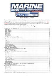
ABOVE: Timber beams across the GRP hull ABOVE: Midships decks laid over beams, ABOVE: Bulkhead aft of midships deck<br />
to cerry midships deck beams to be cut away<br />
www.marinemodelmagazine.com FEBRUARY 2010 55