technical methods for highways sampling methods for roads ...
technical methods for highways sampling methods for roads ...
technical methods for highways sampling methods for roads ...

Create successful ePaper yourself
Turn your PDF publications into a flip-book with our unique Google optimized e-Paper software.
TECHNICAL<br />
METHODS<br />
FOR<br />
HIGHWAYS<br />
SAMPLING<br />
METHODS<br />
FOR<br />
ROADS<br />
CONSTRUCTION<br />
MATERIALS
PREFACE<br />
TECHNICAL METHODS FOR HIGHWAYS (TMH)<br />
is a seriod complementing the TECHNICAL<br />
RECOMMENDATIONS FOR HIGHWAYS (TRH)<br />
series. The TRHs are intended as guides <strong>for</strong> the<br />
practicing engineer and leave room <strong>for</strong> engineering<br />
judgement to be used. The TMHs are morein the<br />
nature of manuals <strong>for</strong> engineers, prescribing <strong>methods</strong><br />
to be used in various road design and construction<br />
procedures. It is hoped that the use of these manuals<br />
will produce uni<strong>for</strong>m results throughout the country.<br />
The TMH series is also printed and distributed by the<br />
National Institute <strong>for</strong> Transport and Road Research<br />
(NITRR) on behalf of the committee <strong>for</strong> State Road<br />
Authorities (CSRA). Any comments or queries on the<br />
document should be addressed to: The director,<br />
National Institute <strong>for</strong> Transport and Road Research,<br />
CSIR, P O Box 395, Pretoria, 0001.<br />
ACKNOWLEDGEMENT<br />
This TMH was prepared by the Materials Testing Subcommittee<br />
of the Highway Materials Committee<br />
which is in turn a sub-committee of the Committee <strong>for</strong><br />
State Road Authorities (CSRA). It carries the full<br />
approval of the CSRA.
SYNOPSIS<br />
TMH5 gives detailed <strong>methods</strong> <strong>for</strong> taking samples of<br />
materials that need to be tested <strong>for</strong> road construction<br />
purposes. Methods of <strong>sampling</strong> natural materials,<br />
stockpiled material (both treated and untreated) and<br />
pavement layers are described. Instructions are also<br />
given <strong>for</strong> sample division using a riffler or by<br />
quartering. In the final chapters the background to<br />
<strong>sampling</strong>, i.e. the necessity <strong>for</strong> <strong>sampling</strong>, evaluation of<br />
test results and the reasons behind the <strong>methods</strong> used,<br />
are discussed. TMH5 is a companion volume to<br />
TMH1 in the Technical Methods <strong>for</strong> Highways series.
CONTENTS<br />
Page<br />
Preface<br />
Synopsis<br />
iii<br />
iv<br />
PART I<br />
SAMPLING METHODS<br />
CHAPTER 1 Foreword 1<br />
CHAPTER 2 Definitions of terms used 2<br />
CHAPTER 3 Specific <strong>methods</strong> <strong>for</strong> <strong>sampling</strong> road construction 4<br />
A. NATURAL MATERIALS<br />
MA1 Sampling of a natural rock mass 5<br />
MA2 Sampling from a conveyor belt 7<br />
MA3 Sampling by auger 9<br />
MA4 Sampling of water <strong>for</strong> chemical and/or bacteriological tests 10<br />
B. STOCKPILED MATERIAL<br />
Untreated materials<br />
MB1 Sampling of stockpiles 12<br />
MB2 Sampling from a conveyor belt 14<br />
MB3 Sampling of cement of lime 16<br />
MB4 Sampling of bituminous binders 18<br />
MB5 Sampling of road marking paint 20<br />
MB6 Sampling of steel <strong>for</strong> concrete rein<strong>for</strong>cement 21<br />
Treated materials<br />
MB7 Sampling of premixed asphalt 22<br />
MB8 Sampling of slurry mixes 24<br />
MB9 Sampling of freshly mixed concrete 25<br />
MB10 Sampling of treated pavement layers to determine content and distribution of the stabilizer 27<br />
C. PAVEMENT LAYERS<br />
MC1 Sampling of road pavement layers 29<br />
MC2 Sampling of asphalt and concrete from a completed layer or structure 31<br />
D. GENERAL METHODS<br />
MD1 Division of a sample using the riffler 33<br />
MD2 Division of a sample by quartering 35<br />
PART II BACKGROUND TO SAMPLING AS APPLIED TO ROAD CONSTRUCTION<br />
MATERIALS 37<br />
CHAPTER 4 Random <strong>sampling</strong> <strong>for</strong> road construction quality control 38<br />
CHAPTER 5 Assessment of test results through evaluation and understanding of the sample taken 43<br />
CHAPTER 6 Determination of sample size and sample density 47<br />
CHAPTER 7 Division, making and proposed frequencies of samples 49
LIST OF FORMS<br />
TMH5-1 Data <strong>for</strong>m <strong>for</strong> borrow pits : samples of gravel/soil/rock/sand 6<br />
TMH5-2 Soil survey <strong>for</strong>m 8<br />
LIST OF FIGURES<br />
1 Slotted tube sampler <strong>for</strong> bulk cement 17<br />
2 Tube sampler <strong>for</strong> packaged cement 17<br />
3 The riffler 34<br />
4 Quartering on even hard clean surface 35<br />
5 Quartering on canvas sheet 35
PART I<br />
SAMPLING METHODS<br />
CHAPTER 1<br />
FOREWORD<br />
(b)<br />
can be used to derive a <strong>sampling</strong> plan in cases<br />
which are not covered by Part I.<br />
This manual has a twofold purpose. Part I describes<br />
the <strong>methods</strong> prescribed <strong>for</strong> specific applications. The<br />
idea is to supplement the <strong>methods</strong> in due course so<br />
that eventually all the important material conditions<br />
will be covered in this Part.<br />
Part II is intended as a manual which:<br />
(a) can be used during the theoretical training of<br />
students<br />
As discussed in Chapter 5 <strong>sampling</strong> sizes and <strong>methods</strong><br />
are very often limited by economic considerations. The<br />
<strong>sampling</strong> plans given in Part I do not there<strong>for</strong>e always<br />
comply with the principles stated in Part II as regards<br />
the number of samples needed.<br />
However, it can be categorically stated that the<br />
specified plans are tried and tested and will usually be<br />
found to be realistic when the <strong>sampling</strong> costs are<br />
weighed against the value of the in<strong>for</strong>mation obtained.
CHAPTER 2<br />
DEFINITIONS OF TERMS USED<br />
N.B<br />
Since these definitions <strong>for</strong>m the basis of all<br />
discussions in this document, it is suggested that<br />
the reader make sure that he thoroughly<br />
understands them be<strong>for</strong>e he uses the rest of the<br />
manual.<br />
1. SAMPLE<br />
A sample is a portion or a combination of<br />
portions of a lot of a material whose degree of<br />
representation is not necessarily important and is<br />
there<strong>for</strong>e not specified. (See Definition 3.)<br />
2. REPRESENTATIVE SAMPLE<br />
A representative sample is a portion or a<br />
combination of portions of a lot of a material<br />
whose degree of representation is important<br />
and is there<strong>for</strong>e specified.<br />
(It is important to understand that the<br />
representation of a sample varies between the<br />
extremes of being poorly representative and<br />
absolutely representative. This simply means<br />
that the larger the sample in proportion to the lot,<br />
the more representative it becomes, until the<br />
whole lot is tested and one may talk in terms of<br />
absolute representation.)<br />
3. SAMPLE LOT<br />
A lot of material means a discrete specific<br />
quantity of the material which can <strong>for</strong> all<br />
practical purposes be regarded as a separate<br />
entity and which does not inherently vary<br />
disproportionately in respect of the determining<br />
characteristics. (See Definition 4.)<br />
(The size of a lot is usually determined by:<br />
(a) The consignment or delivered quantity.<br />
(b) The way in which it is stored when the<br />
sample is taken.<br />
(c) The variation of the characteristics of the<br />
material.<br />
A sample lot is there<strong>for</strong>e the specific heap, load,<br />
tank, drum or quantity of material which can be<br />
represented by a specific sample.)<br />
4. DETERMINING CHARACTERISTICS OF<br />
A MATERIAL<br />
These are characteristics of a material which will<br />
determine its per<strong>for</strong>mance in the specific use<br />
<strong>for</strong> which it is intended.<br />
(The colour of gravel has no direct influence on<br />
its per<strong>for</strong>mance as a road foundation material.<br />
The colour of the gravel is there<strong>for</strong>e a <strong>for</strong>tuitous<br />
or non-determining characteristic.)<br />
5. MINIMUM ACCEPTABLE SIZE OF A<br />
SAMPLE<br />
This is the smallest quantity of material which<br />
can serve as a sample provided that the<br />
determining characteristics of the material can be<br />
measured with an acceptable degree of accuracy<br />
by means of such a sample.<br />
6. MAXIMUM ACCEPTABLE SIZE OF A<br />
SAMPLE<br />
The maximum acceptable size of a sample is the<br />
largest sample from which the desired degree of<br />
representation or accuracy can be obtained<br />
relative to the purpose <strong>for</strong> which the sample was<br />
taken.<br />
7. PRIMARY OR FIELD SAMPLE<br />
This is the sample originally taken from the lot at<br />
the storage site, and its size is determined by the<br />
degree of representation or accuracy can be<br />
obtained relative to the purpose <strong>for</strong> which the<br />
sample was taken.<br />
8. SECONDARY OR LABORATORY<br />
SAMPLE<br />
This is the sample taken from the original sample<br />
which is used to extract the test samples. A<br />
secondary sample is divided up to provide the<br />
secondary sample is usually obtained by division<br />
of the original sample on site and its size is<br />
determined by the specific tests <strong>for</strong> which it is<br />
needed.
9. TERTIARY OR TEST SAMPLE<br />
This is the material used <strong>for</strong> a specific test. It is<br />
extracted from the secondary sample and its<br />
quantity depends on the quantity prescribed <strong>for</strong><br />
the particular test which is to be done.<br />
10. INCREASE OF THE NUMBER OF TESTS<br />
When the sample size as prescribed by the test<br />
method is too small to ensure a specified degree<br />
of accuracy, the number of tests must be<br />
increased to give greater confidence about the<br />
results obtained.<br />
11. REPRODUCIBILITY OF A TEST<br />
This is the degree of variation between the results<br />
obtained by the same operator repeating a test on<br />
the same material. This factor measures<br />
there<strong>for</strong>e measures the human influence or<br />
human error in the execution of a test.<br />
12. REPEATABILITY OF A TEST<br />
This is the degree of variation between the results<br />
obtained by the same operator repeating a test on<br />
the same material. This factor there<strong>for</strong>e<br />
measures the repeatability of the same test under<br />
constant conditions, or in other words the<br />
precision of the test.<br />
13. SINGLE SAMPLE<br />
A single sample is a sample taken from a heap or<br />
a container in a random or non-random manner.<br />
14. COMPOUND SAMPLE<br />
A compound sample is composed of a number of<br />
single samples taken in a random or non-random<br />
manner. (Cf. Definition 13.)<br />
15. MEAN SAMPLE<br />
A mean sample consists of a series of single<br />
samples taken according to a predetermined fixed<br />
pattern, the size of every single sample being in<br />
proportion to the quantity of material it<br />
represents out of the whole. (See Definition 13.)<br />
16. APPROXIMATE MEAN SAMPLE<br />
A sample consisting of a series of single samples<br />
taken according to a predetermined fixed pattern,<br />
the size of every single sample being in<br />
proportion to the quantity of material it<br />
represents out of the whole. (See definitions 13<br />
and 15.)<br />
17. SAMPLE WITH CONSTANT<br />
CHARACTERISTICS<br />
A sample whose determining characteristics are<br />
normally remain constant, unless they are<br />
artificially changed.<br />
18. SAMPLE WITH CHANGING<br />
CHARACTERISTICS<br />
A sample whose determining characteristics are<br />
normally in the process of changing, unless they<br />
are artificially kept constant.<br />
19. SAMPLE WITH CHANGED<br />
CHARACTERISTICS<br />
A sample whose determining characteristics have<br />
been changed externally.
CHAPTER 3<br />
SPECIFIC METHODS FOR SAMPLING<br />
ROAD CONSTRUCTION MATERIALS
NATURAL MATERIALS<br />
SAMPLING METHOD MA 1<br />
SAMPLING OF A NATURAL ROCK MASS<br />
1. SCOPE<br />
This method describes the taking of samples<br />
from a test pit in a natural rock mass when the<br />
rock is to be crushed <strong>for</strong> use in concrete,<br />
surfacings, bases, subbases, etc.<br />
2. APPARATUS<br />
2.1 For taking samples from test pits blasted<br />
with explosives<br />
2.1.1. A prospecting pick.<br />
2.1.2. A suitable tape measure.<br />
2.1.3. A spade.<br />
2.1.4. A pick.<br />
2.1.5. A sledge-hammer with a mass of<br />
approximately 5 kg.<br />
2.1.6. A suitable crowbar.<br />
2.1.7. Suitable canvas sheets approximately 2 x 2 m.<br />
2.1.8. Suitable containers <strong>for</strong> rock samples such as<br />
strong canvas bags.<br />
2.2 For taking cores obtained with the aid of a<br />
core drill<br />
2.2.1 A suitable tape measure.<br />
2.2.2 Suitable containers <strong>for</strong> the packing of cores<br />
such as a wooden box with partitions in which<br />
the cores can be firmly packed so that they<br />
cannot slide together or become mixed up<br />
during transport and handling of the box.<br />
3. SAMPLE SIZE<br />
3.1 Samples from test pits blasted with<br />
explosives<br />
At lease 70kg of each rock type that is<br />
separately identified and sampled, should be<br />
obtained.<br />
3.2 Cores obtained with the aid of a core drill<br />
Where possible at alest 70 kg of each rock<br />
type that is separately identified and sampled,<br />
should be obtained. If the quantity of material<br />
that can be obtained from one borehole is<br />
insufficient, more pits must be drilled adjacent<br />
to the first hole. Alternatively, the cores can<br />
be used simply as indicators and larger test<br />
pits can be blasted with explosives and<br />
sampled at a later stage.<br />
4. METHOD<br />
4.1 Test pits blasted with explosives which have<br />
then been opened manually<br />
Inspect the sides of the test pit to their full<br />
depth and record any observable changes in<br />
the rock as well as the depths between which<br />
such changes occur. Characteristicts which<br />
should be taken into account are rock type,<br />
colour, hardness, texture, etc.<br />
Use a crowbar or pick to loosen pieces of each<br />
type of rock from each wall of the test pit and<br />
place each type in a separate container. If the<br />
pieces are too large <strong>for</strong> the containers, they<br />
may be broken up with the aid of the<br />
sledgehammer. If there is not a large variety<br />
of rock types, some of the loose material taken<br />
from the test pit can be selected outside of the<br />
pit and each type can be placed in a separate<br />
container.<br />
Any loose earth or gravel layers on top of the<br />
rock mass or which occur in seams between<br />
the layers of rock must be sampled separately<br />
in accordance with <strong>sampling</strong> method MA2 if it<br />
is to be used <strong>for</strong> some or other purpose.<br />
The sample containers must all be clearly and<br />
indelibly marked so that the samples can be<br />
identified when they arrive in the laboratory.<br />
(See paragraph 4 of Chapter 7.)<br />
4.2 Cores taken with the aid of a core drill<br />
Place the cores in a suitable box with<br />
partitions so that they are in order from the<br />
shallowest to the deepest part of the borehole<br />
and can be identified and measured as such<br />
when they arrive in the laboratory.<br />
The partitions in the box must be narrow<br />
enough to ensure that the cores remain in<br />
position and do not become mixed up in the<br />
box.<br />
5 REPORTING<br />
The samples must be sent to the laboratory<br />
under cover of a properly composed report or
a suitable borrow pit data <strong>for</strong>m (see <strong>for</strong>m<br />
TMH5-1). The report or <strong>for</strong>m must contain<br />
the full particulars of every sample, <strong>for</strong><br />
example test pit number, sample number,<br />
depths between which the samples were taken,<br />
description of the material type, what sort of<br />
containers were used to send the samples to<br />
the laboratory and how many containers there<br />
are of each sample.<br />
determined according to the definitions in<br />
TRH2 and must be indicated on the sketch<br />
with the necessary symbols.<br />
A sketch of the rack mass and its environment<br />
and also of the position of each test pit must<br />
accompany the report or borrow pit data sheet.<br />
The land<strong>for</strong>m of the rock mass must be
SAMPLING METHOD MA2<br />
SAMPLING FROM A SAMPLING PIT IN NATURAL<br />
GRAVEL, SOIL AND SAND<br />
1. SCOPE<br />
This method describes the taking of samples<br />
from a test pit with vertical sides, at leas one<br />
metre square and which has been excavated in<br />
a natural deposit of gravel, soil or sand by<br />
means of a pick and shovel or any mechanical<br />
excavator or large auger. The samples may be<br />
needed <strong>for</strong> the centre line survey of the natural<br />
in<strong>for</strong>mation or <strong>for</strong> any of the following<br />
proposed uses:<br />
Gravel <strong>for</strong> subgrade, selected layer, subbase,<br />
basecourse, asphalt and coarse aggregate <strong>for</strong><br />
concrete.<br />
Soil <strong>for</strong> subgrade, selected layer, subbase and<br />
binder.<br />
Sand <strong>for</strong> subgrade, selected layer, as a<br />
stabilizing agent <strong>for</strong> clayey materials and as<br />
fine aggregate <strong>for</strong> concrete and bituminous<br />
mixes.<br />
2. APPARATUS<br />
2.1 A prospecting pick.<br />
2.2 A suitable tape measure.<br />
2.3 A spade.<br />
2.4 A pick.<br />
2.5 Suitable sample containers such as strong<br />
canvas or plastic bags.<br />
2.6 Suitable canvas sheets approximately 2 x 2m<br />
2.7 A riffler with oenongs approximately 25mm<br />
wide, with six matching pans.<br />
2.8 A 19 mm sieve with a recommended diameter<br />
of 450 mm.<br />
2.9 A basin approximately 500 mm in diameter.<br />
3 SAMPLE SIZE<br />
The size of each sample will depend on what<br />
tests are to be done on it. A 70 kg sample will<br />
usually be sufficient but if the material is to be<br />
tested <strong>for</strong> more than one possible use, the size<br />
of each sample will have to be increased. (See<br />
paragraphs 2.1 and 2.2 of Chapter 6.) A<br />
sample may, and usually will, consist of more<br />
than one bag of material.<br />
4 METHOD<br />
Inspect the sides of the test pit to their full<br />
upper edge of the test pit. Now sample every<br />
distinguishable gravel, soil or sand layer by<br />
holding a spade or canvas sheet at the lower<br />
level of the layer against the side of the pit and<br />
by cutting a sheer groove to the full depth of<br />
the layer with a pick a or spade. Place the<br />
material obtained in this way in ample bags.<br />
The canvas sheet may also be spread out on<br />
the floor of the test pit. At least twice the<br />
amount of material needed <strong>for</strong> the final sample<br />
must be loosened from the layers. Once all the<br />
layers have been sampled the material from<br />
each layer must be combined on either a clean,<br />
hard, even surface or on a canvas sheet and<br />
properly mixed with a spade.<br />
Now quarter out a representative sample of the<br />
layer as explained in <strong>methods</strong> MD1 and MD2.<br />
(See note 6.1 below and paragraph 3.2 of Test<br />
Methods A1 in TMH1.)<br />
It is customary to fill one small sample bag<br />
which can holed about 10kg, and two or three<br />
larger bags each holding about 30 to 40 kg.<br />
When numerous test pits are made in a deposit<br />
and the materials differ very little, it is only<br />
necessary to fill large bas of each material type<br />
at every second or third test pit. Here the<br />
sampler must be guided by his discretion and<br />
experience. The sample bags (or other<br />
containers) must all be clearly and indelibly<br />
marked so that the samples can be identified in<br />
the laboratory. The identifying reference must<br />
agree with that given in the covering report or<br />
<strong>for</strong>m. (See paragraph 4 of Chapter 7.)<br />
5 REPORTING<br />
The samples must be sent to the laboratory<br />
under cover of a properly composed report and<br />
data sheet(s) (see soil survey <strong>for</strong>m TMH5-2<br />
and borrow pit data <strong>for</strong>m TMH5-1). Full<br />
particulars about every sample must be given,<br />
<strong>for</strong> example stake value, sample number of<br />
mark, depths between which the samples were<br />
taken, description of the material, type of<br />
containers used to send the samples to the<br />
laboratory, and how many containers there are<br />
of each sample.
In the case of a proposed borrow pit, a<br />
direction-orientated sketch of the<br />
environment in which the deposit occurs<br />
must accompany the report and borrow pit<br />
data sheets.<br />
All noteworthy landmarks must be indicated<br />
on the sketch. Every test pit must be clearly<br />
shown and the distance of the proposed<br />
source from the centre line of the road must<br />
be given in kilometers, to the nearest 0,1km.<br />
The land<strong>for</strong>m in which the proposed source<br />
occurs must be determined according to the<br />
definitions in TRH2 and must be indicated<br />
on the sketch with the necessary symbols.<br />
6 NOTES<br />
6.1 Since one is often working with rather large<br />
quantities of material in this type of <strong>sampling</strong>,<br />
the capacity of the riffling pans may often be<br />
too small to contain even half of the material<br />
obtained after the first quartering. If<br />
insufficient pans are available, another heap<br />
must be made on a clean, hard, even surface or<br />
canvas sheet. This heap must then be mixed<br />
and divided with a spade as be<strong>for</strong>e. (See<br />
paragraph 1 of Chapter 7 and Methods MD1<br />
and MD2.)<br />
6.2 Safety precautions<br />
In accordance with Regulation D16 of the<br />
Factories, Machinery and Building Work<br />
Act, no excavation deeper than 1.5m may be<br />
made unless:<br />
(a) it is properly popped and braced;<br />
(b) the gradient of the sides is at least<br />
equal to the angle of repose;<br />
(c) it is in firm rock.
SAMPLING METHOD MA3<br />
SAMPLING BY AUGER<br />
1. SCOPE<br />
This method involves in-situ <strong>sampling</strong> of<br />
natural gravel, soil or sand by meand of<br />
hand or power augers. Such <strong>sampling</strong> is<br />
done <strong>for</strong> a centre line survey of the natural<br />
<strong>for</strong>mation or <strong>for</strong> borrow pit surveys <strong>for</strong><br />
subgrade, selected layer, subbase, base, or<br />
coarse or fine aggregate <strong>for</strong> concrete or<br />
asphalt.<br />
2 APPARATUS<br />
2.1 Hand augers approximately 50 to 300 mm in<br />
diameter.<br />
2.2 Power augers approximately 600 mm in<br />
diameter.<br />
2.3 A prospecting pick.<br />
2.4 A suitable tape measure to measure the<br />
<strong>sampling</strong> depth in millimeters.<br />
2.5 Shovels.<br />
2.6 Picks.<br />
2.7 Suitable <strong>sampling</strong> bags made of canvas or<br />
plastic.<br />
2.8 Suitable canvas sheets approximately 2 x<br />
2m.<br />
2.9 A riffler with 25 mm openings and pans.<br />
2.10 Containers approximately 500 mm in<br />
diameter.<br />
3 SAMPLE SIZE<br />
The size of the sample will depend on the<br />
tests <strong>for</strong> which it is required, but usually a<br />
sample of 70 kg is sufficient.<br />
4 METHOD<br />
4.1 The work is done by drilling into the ground<br />
with the auger to the required depth,<br />
withdrawing the auger, and then removing<br />
the soil <strong>for</strong> examination and <strong>sampling</strong>.<br />
Reinsert the auger in the hole and repeat the<br />
process.<br />
Where various different types of soil are<br />
horizon occurs. When sufficient material is<br />
obtained <strong>for</strong> testing, e.g. when a 50 mm<br />
auger is used, the in<strong>for</strong>mation gathered is<br />
simply used to record the soil profile. When<br />
sufficient material is removed by drilling a<br />
laboratory sample is obtained by quartering<br />
and riffling as described in Methods MD1<br />
and MD2.<br />
4.2 In the case of harder rock, when the power<br />
auger may cause pulverization, it is<br />
preferable to use the following procedure.<br />
Drill a hole, usually about 600 mm in<br />
diameter, to the full depth required. Drill a<br />
second hole approximately 0,5 to 1,0 m asay<br />
from the first hole, depending on the<br />
quantity of material needed <strong>for</strong> the sample,<br />
to the depth of the first horizon which is to<br />
be sampled. Remove all the material<br />
between the two holes up to this depth and<br />
place it on a hard, clean soil surface or on a<br />
canvas sheet. Drill the second hole to the<br />
depth of the second horizon which is to be<br />
sampled and removed all the material<br />
between the two holes as described above,<br />
placing it on a separate canvas sheet. Repeat<br />
the process to the full depth of the first hole.<br />
Alternatively, samples may be taken from a<br />
single hole by cutting a groove in the<br />
material from the side of the hole as<br />
described in Method MA2.<br />
5 REPORTING<br />
See Method MA2.<br />
REFERENCE<br />
ASTM-D1452.
SAMPLING METHOD MA4<br />
SAMPLING OF WATER FOR CHEMICAL AND/OR<br />
BACTERIOLOGICAL TESTS<br />
1 SCOPE<br />
The method describes the procedure which<br />
should be followed when samples of water<br />
are taken <strong>for</strong> chemical and/or bacteriological<br />
tests. The tests and requirements are<br />
described in SABS 241-1971.<br />
2 APPARATUS<br />
2.1 Containers <strong>for</strong> samples <strong>for</strong> chemical tests<br />
Clean glass bottles with a capacity of<br />
approximately 2 l with close-fitting clean<br />
stoppers or covers, preferably also of glass.<br />
2.2 Containers <strong>for</strong> samples <strong>for</strong> bacteriological<br />
tests<br />
Only suitable sterilized containers supplied<br />
by the test laboratory may be used.<br />
3 SAMPLE SIZE<br />
3.1 Samples <strong>for</strong> chemical tests<br />
At least 10 l per sample.<br />
3.2 Samples <strong>for</strong> bacteriological tests<br />
3.2.1 Volume and number of samples: Each<br />
samples must consist of at least 250 ml and<br />
the minimum number of samples that may<br />
be taken at one place will depend on the<br />
number of users to be served. (No more than<br />
one sample per day may be taken.)<br />
4 METHOD<br />
4.1 Samples <strong>for</strong> chemical tests (see notes 6.1<br />
and 6.2)<br />
4.2 Preparation of glass bottles<br />
Clean the bottles and their stoppers or covers<br />
thoroughly be<strong>for</strong>e use. If possible the<br />
bottles should be washed with a nitric acid<br />
solution and then thoroughly rinsed out with<br />
water to remove the acid. Half-fill each<br />
bottle with the water from which a sample is<br />
to be taken, shake thoroughly and then<br />
empty it. Repeat this procedure three more<br />
times be<strong>for</strong>e starting to take the sample.<br />
4.1.2 Sampling<br />
4.1.2.1 From a tap: Turn the tap on fully and allow<br />
the water to flow <strong>for</strong> two minutes be<strong>for</strong>e<br />
taking the sample. To prevent unnecessary<br />
aeration while the sample is being taken,<br />
turn the tap while the sample is being taken,<br />
turn the tap so that it is only partially open<br />
and fill the bottle to within 15 mm of the top<br />
of the neck. Close with the stopper or cover<br />
to make a tight seal and label the bottle<br />
properly with the name of the sender, the<br />
date and the time of <strong>sampling</strong>, and any<br />
special identifying mark.<br />
4.1.2.2 From the borehole or well: If samples are<br />
being taken from a borehole or well it is<br />
preferable to take them from a pump outlet<br />
pipe through which water has been pumping<br />
continuously <strong>for</strong> at least 24 hours.<br />
Thereafter follow the method described in<br />
paragraph 4.1.2.1 above.<br />
4.1.2.3 From a stream, lake or fountain: Remove the<br />
stopper from the sample container and<br />
completely immerse the container in the<br />
water, holding it at the base. Allow it to fill<br />
by holding it pointing upstream in running<br />
water or moving it slowly <strong>for</strong>ward in<br />
standing water. Do not disturb the sediment<br />
or collect any of it in the sample. If walking<br />
in the water cannot be avoided, the sampler<br />
should keep walking upstream while taking<br />
the samples. If it is necessary to use a boat<br />
to obtain a sample at a suitable depth from a<br />
lake or dam, the boat should be propelled<br />
with as little disturbance as possible to the<br />
<strong>sampling</strong> site. The sample container can<br />
then be attached to a suitable rod and be<br />
carefully filled by immersing it in the water<br />
and moving it slowly <strong>for</strong>ward as described<br />
above. As soon as the container is full, it<br />
should be closed with the stopper and must<br />
then be properly labeled as described in<br />
paragraph 4.1.2.1.<br />
4.2 Samples <strong>for</strong> bacteriological tests<br />
4.2.1 General<br />
Only containers supplied by the test<br />
laboratory and which are sterile and suitable<br />
<strong>for</strong> immediate use may be used. Be<strong>for</strong>e each<br />
sample is taken the sampler must wash his<br />
hands thoroughly. While the sterile sample<br />
container is being handled no surface of the<br />
cover or stopper which may come into<br />
contact with the sample or with the inside<br />
surface of the cover may come into contact<br />
with the hand or any other object; under no<br />
circumstances may the covers be laid down.
4.2.2 Sampling from a tap or pump<br />
Allow the water to glow <strong>for</strong> at least two<br />
minutes so that the pipe supplying the tap is<br />
thoroughly flushed out, then stop the flow<br />
and wash the mouth of the tap or pipe with a<br />
spirit burner (or other suitable type) until it<br />
is really hot. Open the tap to its fullest and<br />
allow the water to flow again until the tap<br />
has cooled down. Now fill the container<br />
with water from the running tap until it is<br />
full and close with the stopper or cover to<br />
<strong>for</strong>m a tight seal. Label the sample clearly<br />
with the name of the sender, the date and<br />
time of <strong>sampling</strong>, and any special identifying<br />
mark.<br />
4.2.3 Sampling from a stream, reservoir or dam<br />
Hold the box of the container in one hand,<br />
remove the cover with the other hand and<br />
immediately immerse the container about<br />
300 mm below the surface of the water. In<br />
running water the container must be held<br />
with its mouth pointing upstream and in<br />
standing water it must be moved so that no<br />
water which has come into contact with the<br />
hand gets into the container. Once the<br />
container has been filled, remove it from the<br />
water and seal it tightly with the stopper or<br />
cover. Label the container clearly with the<br />
name of the sender, the date nad time of<br />
<strong>sampling</strong> and any special identifying mark.<br />
5 REPORTING<br />
Every sample must be accompanied by a<br />
report containing the following particulars:<br />
Name and address of the organization or<br />
person requesting the tests.<br />
6 NOTES<br />
Name and number of the farmer, plot or erf<br />
and the magisterial district.<br />
Type of test required (bacteriological or<br />
chemical or both).<br />
Date and time at which the sample was<br />
taken.<br />
Date and time at which the sample was<br />
dispatched.<br />
Name of sampler.<br />
Description of the place at which samples<br />
were taken, i.e. the storage container<br />
(reservoir, tank, etc.), well, borehole, spring<br />
or stream, as applicable.<br />
The date on which the last rain fell and<br />
whether it was heavy or not.<br />
Whether the water has an unpleasant smell<br />
or taste.<br />
The approximate number of persons who<br />
receive (use) water from the source or<br />
supply.<br />
6.1 Samples must be sent to the laboratory as<br />
soon as possible, since immediate chemical<br />
analysis (or stabilization) of the samples is<br />
essential.<br />
6.2 The water should be sampled at least four<br />
times every year at the following times:<br />
at the beginning of the rainy season:<br />
in the middle of the rainy season;<br />
at the end of the rainy season;<br />
in the middle of the dry season.<br />
REFERENCE<br />
SABS 241-1971
STOCKPILED MATERIAL<br />
Untreated materials<br />
SAMPLING METHOD MB1<br />
SAMPLING OF STOCKPILES<br />
1 SCOPE<br />
This method describes the procedure to<br />
be followed when stockpiles are<br />
sampled (see 6.1). The stockpiles may<br />
consist of:<br />
Natural gravel, soil or sand;<br />
Crushed rock <strong>for</strong> base or subbase;<br />
Screened-out crusher dust <strong>for</strong> binder,<br />
fine aggregate <strong>for</strong> concrete or fine<br />
aggregate <strong>for</strong> bituminous mixes;<br />
Crushed single-sized aggregate <strong>for</strong><br />
bituminous or concrete work.<br />
2 APPARATUS<br />
2.1 Shovels.<br />
2.2 Picks.<br />
2.3 A mechanical loader-digger (if<br />
available).<br />
2.4 Suitable sample bags (or other<br />
containers).<br />
2.5 Suitable canvas sheets.<br />
2.6 A riffler with 25 mm openings and six<br />
matching pans.<br />
2.7 A 19 mm sieve with a recommended<br />
diameter of 450 mm.<br />
2.8 A basin with a diameter of<br />
approximately 500 mm.<br />
3 SAMPLE SIZE<br />
The sample size will depend on the<br />
proposed use of the material and the<br />
tests which have to be carried out on it.<br />
(See paragraph 2 of Chapter 6.) The<br />
following tables give an indication of<br />
the minimum secondary sample sizes<br />
<strong>for</strong> every type of material. (See note<br />
6.3.)<br />
Proposed use<br />
Pavement and<br />
<strong>for</strong>mation layers<br />
(Gravels, soils and<br />
crushed stone)<br />
Fine aggregate <strong>for</strong><br />
concrete and<br />
Mass<br />
Gradings and<br />
constants: 10 kg<br />
Cali<strong>for</strong>nia Bearing<br />
Ratio: 60 kg<br />
20 kg<br />
bituminous mixes<br />
Single-sized<br />
coarse aggregate<br />
<strong>for</strong> concrete mixes<br />
and bituminous<br />
surfacings<br />
25 kg<br />
4 METHOD<br />
4.1 Sampling while stockpile is being<br />
<strong>for</strong>med by the off-loading of material<br />
Select one or two positions on the<br />
consolidated surface of every layer of<br />
the stockpile at random while the pile is<br />
being <strong>for</strong>med.<br />
Make a vertical test hole through the<br />
layer (or as deep as is practically<br />
possible) with the pick and shovel.<br />
Place a canvas sheet in the bottom of the<br />
hole and cut an groove in the side of the<br />
hole from top to bottom, letting this<br />
material fall onto the canvas sheet.<br />
Gather a sufficient quantity of material<br />
by cutting successive grooves,<br />
frequently raising the canvas sheet from<br />
the h9ole and tipping its contents onto<br />
another canvas sheet on the surface.<br />
Mix the material on the canvas sheet<br />
and divide it, by means of the riffler and<br />
the quartering method (refer to<br />
paragraph 1 of Chapter 7 and Methods<br />
MD1 and MD2), into the required size<br />
so that each sample bag or container<br />
contains a representative sample of the<br />
material taken from the test hole.<br />
4.3 Sampling from an already completed<br />
stockpile<br />
Select at least twelve <strong>sampling</strong> positions<br />
in a random manner. (See 6.2)<br />
Approximately half the positions may<br />
be on top of the stockpile if its surface is<br />
fairly large. (Also see paragraph 2 of<br />
Chapter 6.)
4.2.1 Sampling with a mechanical loaderdigger<br />
42.1.1 From the sides of a stockpile<br />
Scooping from the sides of the stockpile<br />
from the bottom towards the top, fill the<br />
bucket of the loader-digger and deposit<br />
the material on a clean hard surface –<br />
the flat steel back of a truck or a hard<br />
clean ground surface are suitable. Mix<br />
the material thoroughly with the spade<br />
and quarter it out into smaller equal<br />
parts using the quartering method ( ref<br />
to Method MD 2) until a quantity<br />
approximately twice the size is<br />
obtained. (See note 6.2)<br />
Deposit this material on a canvas sheet,<br />
mix it thoroughly again and further<br />
divide it with the aid of the riffler (see<br />
Method MD1) until the desired sample,<br />
consisting of one or more bags (or<br />
containers), each representative of the<br />
sample, has been obtained.<br />
4.2.1.2 From the top of the stockpile<br />
Use the load-digger to make a hole<br />
approximately 2 m deep. (See note 6.2 )<br />
Now scoop a load of material from the<br />
side of the hole, working from the<br />
bottom to the top, and deposit it in the<br />
back of a truck. Mix and divide the<br />
sample as described in paragraph<br />
4.2.1.1 above.<br />
4.2.2 Sampling with pick and shovel<br />
4.2.2.1 From the sides of a stockpile<br />
Using shovels, dig a groove from the<br />
top to the bottom of the stockpile.<br />
(See note 6.2) Remove all the material<br />
that has collected at the bottom of the<br />
groove as a result of the digging. Place<br />
a canvas sheet of suitable size at the<br />
bottom of the groove and using picks<br />
and shovels loosen a uni<strong>for</strong>m thickness<br />
of material down the full length of the<br />
groove. Throw this material onto a<br />
canvas sheet, mix it thoroughly and<br />
quarter it as described in<br />
paragraph4.2.1.1 above.<br />
4.2.2.2 From the top of the stockpile<br />
Dig a vertical test hole with a pick and<br />
shovel, preferably 2 m deep ( or as<br />
deep as practically possible). (See note<br />
6.2.) Place a canvas sheet in the<br />
bottom of the hole and cut a uni<strong>for</strong>m<br />
groove into the holefrom the top to the<br />
bottom so that the material falls onto the<br />
sheet, or throw it onto the sheet.<br />
Continue with this method until you<br />
have enough material, raising the<br />
canvas sheet as often as necessary and<br />
depositing the material on another<br />
canvas sheet on the surface of the<br />
stockpile. Now mix thoroughly all the<br />
material, raising the canvas sheet as<br />
often as necessary and depositing the<br />
material on another canvas sheet on the<br />
surface of the stockpile. Now mix<br />
thoroughly all the material deposited on<br />
the canvas sheet on the surface and<br />
quarter it as described in 4.2.1.1 above.<br />
5 REPORTING<br />
Samples taken from stockpile are often<br />
tested in field labortaries. In such cases<br />
a proper record must be kept of the<br />
sample number, date of <strong>sampling</strong> ,<br />
position in the stockpile, description of<br />
the material , depth of test hole, etc.<br />
When samples from a stockpile are sent<br />
to a central laboratory, they must be<br />
send under cover of a properly<br />
composed report in wich full details of<br />
the stockpile and samples are given.<br />
Important particulars about the sample<br />
are the sample number, the position at<br />
which sampled, depths between which<br />
the sample was taken (oright of the side<br />
from which it was taken), description<br />
of the material of which the sample<br />
consists, number and type of bags (or<br />
containers) in which the samples is<br />
contained and the proposed use of the<br />
material. (See also Paragraph 4 of<br />
Chapter 7. )<br />
A sketch of the stockpile showing the<br />
positions of the <strong>sampling</strong> points at<br />
which the various samples were taken<br />
must be included with the report.
6 4 000 m, one sample must be taken NOTES <strong>for</strong><br />
6.1 Sampling from a stockpile should, if at<br />
All possible, be done while the stockpile<br />
every 1 000 ,m, i.e.<br />
<strong>for</strong> 0-4 000 m- 4 samples<br />
. is being <strong>for</strong>med. Whenever a layer has<br />
Been completed <strong>sampling</strong> points should<br />
Be taken by making test holes in the<br />
layer and taking samples from them.<br />
However, stockpiles are often scraped<br />
<strong>for</strong> 5 000 m – 5 samples<br />
<strong>for</strong> 7 000 m – 7 samples.<br />
The primary sample should consist of at<br />
least 300 kg <strong>for</strong> coarse and 50 kg <strong>for</strong><br />
together in natural material with<br />
fine material. However, since it is<br />
bulldozers, in which case it is better to<br />
wait until the stockpile has been<br />
completed be<strong>for</strong>e taking samples.<br />
impractical to transport such large<br />
quantities, the material is immediately<br />
divided up into the secondary sample<br />
6.2 The number of samples will depend on<br />
The size of the stockpile. At least four<br />
samples must be taken from each<br />
stockpile, but if the pile is greater than<br />
size as shown in paragraph 3. The<br />
tertiary sample size is determined by<br />
the test method.
SAMPLING METHOD MB2<br />
SAMPLING FROM A CONVEYOR BELT<br />
1. SCOPE<br />
This method describes the procedure to<br />
be followed when samples are taken<br />
from a conveyor belt <strong>for</strong> the following<br />
purposes:<br />
crushed or natural material <strong>for</strong> the<br />
gravel layers of a road ( basecourse,<br />
subbase or selected layer);<br />
crushed and/or sieved-out single – sized<br />
aggregate <strong>for</strong> bituminous or concrete<br />
work;<br />
fine aggregate <strong>for</strong> bituminous or<br />
concrete work. N.B. This method is not<br />
suitable if the crushers of a stone<br />
crusher first have to be emptied.<br />
2. APPARATUS<br />
2.1 A suitable spade.<br />
2.2 A 100 mm paintbrush.<br />
2.3 Suitable containers <strong>for</strong> samples such as<br />
strong canvas or plastic bags.<br />
2.4 Two templates whose from corresponds<br />
to that of the conveyor belt.<br />
2.5 Suitable metal pans such as riffling pans<br />
in which to catch the material when it is<br />
taken off the conveyor belt.<br />
2.6 A riffler with openings of<br />
approximately 25 mm and six matching<br />
pans.<br />
2.7 A 19 mm sieve with a recommended<br />
diameter of 450 mm.<br />
2.8 A basin approximately 500mm in<br />
diameter.<br />
3. SAMPLE SIZE<br />
The size of each single sample taken from<br />
the conveyor belt will depend on what<br />
test are to be carried out and on how<br />
homogeneous the material is. The<br />
following table gives an indication of the<br />
minimum masses of the compound<br />
sample which should be aimed at<br />
Maximum Minimum<br />
Aggregate compound<br />
Size<br />
secondary<br />
(mm) size (kg)<br />
75 150<br />
63 125<br />
50 100<br />
37.5 75<br />
25 50<br />
19 25<br />
13.2 15<br />
9.5 and smaller 10<br />
4 METHOD.<br />
Decide during production, in a random<br />
manner, when a single sample should be<br />
taken. Where a conveyer belt is<br />
concerned it is easiest to work on a time<br />
basis, in other words to decide to take<br />
samples at say 3 hours, 5.5 hours and6.3<br />
hours after production has started. At the<br />
designated time the conveyer belt<br />
stopped. Two templates are then placed<br />
in position on the belt such that the<br />
material between the two templates will<br />
yield a single sample which when mixed<br />
and riffled will yield a compound sample<br />
of the size specified in paragraph 3. The<br />
material between the templates is then<br />
carefully scraped off the conveyor belt<br />
into metal pans held next to the belt, and<br />
the dust and fines are brushed off the belt<br />
into pans with the 100 mm paintbrush.<br />
The belt is started again and the above<br />
procedure repeated twice more. The<br />
material sampled is now thoroughly<br />
mixed to <strong>for</strong>m the compound sample and<br />
divided according to Methods MD1 and<br />
MD2 to yield a sample of the desired size.<br />
5 REPORTING<br />
Samples from the conveyor belts are often<br />
tested in field laboratories. In such cases<br />
a proper record must be kept of the<br />
source, the sample number, the date of<br />
<strong>sampling</strong>, a description of the material,<br />
etc. A <strong>for</strong>m similar to TMH5-1 may be<br />
used.
When samples are sent to a central<br />
laboratory, they must be accompanied by<br />
a properly composed report giving full<br />
details about the samples. Important<br />
particulars are the location and proposed<br />
– or approved source, a description of the<br />
material of which the sample is<br />
composed, the number and type of<br />
containers of each sample, the date and<br />
time of <strong>sampling</strong> and the number. (See<br />
also paragraph 4 of Chapter 7)<br />
6 NOTE<br />
6.1 The primary single samples must be large<br />
but never the less in a <strong>for</strong>m which makes<br />
practical handling of the compound<br />
sample possible. Because of the size, the<br />
secondary compound sample as indicated<br />
in paragraph 3 must be divided up<br />
immediately to facilitate the transport<br />
thereof. The tertiary sample size is<br />
determined by test method
1 SCOPE<br />
The method describes the procedures that<br />
should be followed when samples of<br />
cement or lime are taken from:<br />
Bulk stock or consignments;<br />
Containers such as 50 kg bags of cement<br />
or 25 kg bags of lime<br />
2 APPARATUS<br />
2.1 Suitable, clean containers such as tins<br />
with tightly-fitting lids which can be hold<br />
5 kg of cement or lime.<br />
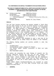
2.2 Suitable equipment <strong>for</strong> taking samples<br />
such as a grooved <strong>sampling</strong> device <strong>for</strong><br />
taking samples from large containers, and<br />
a tube type <strong>sampling</strong> device <strong>for</strong> small<br />
containers such as bags (see drawings).<br />
The <strong>for</strong>mer apparatus must be about 1.7<br />
m long with an outer diameter of about 35<br />
mm. It must consist of two brass<br />
telescopic tubes with corresponding<br />
grooves that can be opened and closed by<br />
turning the inner tube. The outer tube<br />
must have a sharp point to facilitate<br />
penetration into the cement or lime.<br />
3 SAMPLE SIZE<br />
3.1 Cement: Minimum of 2.0 kg <strong>for</strong> each 12<br />
single samples.<br />
3.2 Lime: Minimum of 0.5 kg <strong>for</strong> each<br />
single samples.<br />
4 METHOD<br />
4.1 Cement or lime in bulk containers<br />
If the stock of cement or lime is less than<br />
2 m deep ( see note 6.3) single samples<br />
can be obtained with slotted <strong>sampling</strong>s<br />
device. Take single samples at as many<br />
different depths and well spaced points in<br />
the container as possible, and place each<br />
sample in a separate sample container.<br />
Close the sample container properly to<br />
prevent moisture or air getting to the<br />
sample.<br />
4.2 Cement or lime in bags<br />
Choose the number of bags to be sampled<br />
from the consignment or stock in a<br />
random manner. Push a <strong>sampling</strong> into the<br />
SAMPLING METHOD MB3<br />
SAMPLING OF CEMENT AND LIME<br />
mouth of the bag. Place a thumb over<br />
the airhole of the <strong>sampling</strong> advice and<br />
withdraw the instrument. Empty the<br />
contents of the <strong>sampling</strong> device into a<br />
sample container. Repeat the procedure<br />
until the required quantity has been<br />
obtained. Close both the sample<br />
container and the hole made by the<br />
<strong>sampling</strong> device in the mouth of the bag<br />
tightly so that no air or moisture can get<br />
in.<br />
4.3 Mark or lable each sample, showing<br />
clearly what consignment or stock it was<br />
taken from, the date of <strong>sampling</strong>, the<br />
sample number and from where in the<br />
stock the sample was taken.<br />
5 REPORTING<br />
The samples must be sent to the<br />
laboratory under cover of a full report.<br />
The report must give, amongst others, the<br />
number of each sample, particulars of the<br />
stock or consignment from which the<br />
samples were taken, and the position of<br />
each sample in the stock or consignment.<br />
6 NOTES<br />
6.1 All types of cement and lime<br />
6.2 When the stock is deeper than 2 m, a<br />
more sophisticated apparatus such as a<br />
<strong>sampling</strong> pipe which works on an aircurrent<br />
should be used. Such an<br />
apparatus is capable of taking separate<br />
samples at various depths of lime and<br />
cement.<br />
6.3 Samples must not be taken from broken<br />
bags. The number of samples taken will<br />
depend on the size of the consignment or<br />
stock, but at least 12 single samples must<br />
be taken from each consignment or stock.<br />
References<br />
ASTM: C 183-86 (a)<br />
SABS 471<br />
SABS 626<br />
SABS 831<br />
SABS 824
FIG 1&2 OF TUBE SAMPLER PG 17
SAMPLING METHOD MB4<br />
SAMPLING OF BITUMINOUS BINDERS<br />
1. SCOPE<br />
This method describes the procedure<br />
to be followed when <strong>sampling</strong><br />
bituminous binders from drums or<br />
tankers. Bituminous binders<br />
include:<br />
Bitumen<br />
Tar<br />
Cut-back bitumen<br />
Emulsions<br />
Priming material<br />
2. APPARATUS<br />
2.1 Gas or flame <strong>for</strong> heating the drum<br />
2.2 Sample container (5 L capacity).<br />
(Glass or plastic containers are<br />
preferred <strong>for</strong> emulsions.)<br />
2.3 Sampling tube or thief sample.<br />
2.4 Cleaning material.<br />
3. SAMPLE SIZE<br />
The sample size will depend on the<br />
purpose and type of material, as well<br />
as on the volume and method of<br />
storage. Normally the sample will<br />
be about 4 L.<br />
4. METHOD<br />
4.1 Sampling of all bituminous may<br />
be done using the same basic<br />
principles. However, there are a few<br />
differences which should be taken<br />
into account. (See note 6.1 –6.5 )<br />
4.2 Sampling of bituminous binder in<br />
drums<br />
4.2.1 If the drum has to be heated, e.g in<br />
the case of tar or bitumen, this must<br />
be done slowly and uni<strong>for</strong>mly after<br />
the plug has been removed toallow<br />
the gases to escape. Avoid<br />
overheating any area of the drum.<br />
(See note 6.4. )<br />
4.2.2 Close the drum tightly and roll it<br />
from side to side and invert it until<br />
the contents are thoroughly mixed<br />
4.2.3 Remove the plug from the drum<br />
and take a sample using the<br />
<strong>sampling</strong> tube. Let the tube down<br />
slowly into the drum so that the<br />
level of the binder in the tube stays<br />
the same as the level of the binder<br />
in the drum. Close the tube,<br />
remove it and once the binder<br />
adhering to the outside of the tube<br />
has run off, transfer it to a sample<br />
container.<br />
4.2.4 At least 4 L of binder must be taken<br />
<strong>for</strong> each individual sample. The<br />
quantity taken from each drum will<br />
there<strong>for</strong>e depend on the number of<br />
drums to be represented by one<br />
sample. (See notes. )<br />
4.3 Sampling of bituminous binders<br />
in tankers and distributors<br />
4.3.1 Using a samplig valve<br />
If the tanker or distributor is<br />
provided with a <strong>sampling</strong> valve, it<br />
is very easy to take a sample.<br />
Circulate the contents of the tanker<br />
or distributor to mix it touroughly.<br />
Draw at least 20 L of binder from<br />
the valve o clean it. Then draw at<br />
least 4 L of material into the clean<br />
sample container and seal it<br />
immediately. (See notes)<br />
In this way samples are taken at<br />
least three levels in the tank and<br />
combined to <strong>for</strong>m a total sample of<br />
a least 4 L.<br />
4.4 If necessary, divide the samples as<br />
discussed in Chapter 7 paragraph<br />
1.2. Mark the sample clearly and<br />
indelibly immediately after sealing.<br />
(See paragraph 4 of Chapter 7)<br />
5 REPORTING<br />
Compose a report in the <strong>for</strong>m of a letter<br />
stating the <strong>sampling</strong> method used, the<br />
purpose of and all other essential data.<br />
(See paragraph 4 of Chapter 7)
6 NOTES<br />
6.1 Emulsion are chemically very reactive<br />
and special precautions must be taken to<br />
prevent contamination. There<strong>for</strong>e only<br />
take amples in clean new sample<br />
containers made of glass or plastic.<br />
6.2 The characteristics of emulsions change<br />
very quickly. Test on emulsions must<br />
there<strong>for</strong>e be completed within seven<br />
days. There <strong>for</strong> always dispatch<br />
samples immediately.<br />
6.3 Cut-back bitumens and road tars contain<br />
a fair amount of volatile material. If the<br />
volatile portions evaporate, the<br />
characteristics of the material will<br />
change. There<strong>for</strong>e take care to seal the<br />
container with the sample as soon as<br />
possible. Ensure that cover of the<br />
container is air-tight and that it cannot<br />
become dislodge during transit.<br />
6.4 Penetration bitumens and some tars are<br />
usually too hard to sample when they<br />
are cold. They must be heated gradually<br />
while the binder is being stirred or<br />
circulated. The sample must be<br />
extracted slowly so that the hot binder<br />
does not splash. Use gloves and wear<br />
some protection on the arms when<br />
taking samples.<br />
6.5 The sample container may not be cleaned<br />
with solvent. If the container becomes<br />
soiled on the outside, it should be wiped<br />
down with a clean cloth.<br />
6.6 When binder distributors or tankers<br />
possess a circulation system the<br />
contents should be circulated be<strong>for</strong>e a<br />
sample is taken.
SAMPLING METHOD MB5<br />
SAMPLING OF ROAD MARKING PAINT<br />
1 SCOPE<br />
This method deals with the procedure to<br />
be followed when <strong>sampling</strong> road marking<br />
paint.<br />
2 APPARATUS<br />
2.1 Clean, dry sample containers which have<br />
an air-tight seal.<br />
2.2 Sampling tube or thief sampler (optional).<br />
2.3 Cleaning material<br />
3 SAMPLE SIZE<br />
A single or compound sample of at least<br />
2L is taken.<br />
4 METHOD<br />
Use the following procedure to ensure<br />
that the sample is representive of the<br />
batch.<br />
Examine the container to ensure that the<br />
paint has been contaminated or diluted.<br />
The container must be undamaged and<br />
sealed.<br />
Decant a sample ( or use a <strong>sampling</strong> tube<br />
or thief sampler in the case of the large<br />
containers) into the sample container.<br />
The sample must have a volume of at<br />
least 2 L. The 2 L may be a compound<br />
sample provided the paint is of the same<br />
production batch and type. Dividethe<br />
sample when necessary as explained in<br />
paragraph 1.2 of Chapter 7.<br />
Seal the container and clean the outside of<br />
it.<br />
Mark the container properly with the<br />
name of the paint, the colour, the name<br />
and the manafacturer, the brand name and<br />
the production batch identification.<br />
5 REPORTING<br />
Dispatch the sample with a covering<br />
letter.<br />
6 NOTES<br />
6.1 Make sure that the sample containers will<br />
not come open or leak during transit.<br />
Stir the contents of the container<br />
thoroughly until a homogeneous product<br />
is obtained. Use a clean ladle to prevent<br />
contamination.
SAMPLING METHOD MB6<br />
SAMPLING OF STEEL FOR CONCRETE REINFORCEMENT<br />
1 SCOPE<br />
This method describes the taking of<br />
samples of structural steel <strong>for</strong> determining<br />
the tensile strength and other<br />
characteristics as specified in SABS 920.<br />
The method can also be applied to the<br />
taking of samples <strong>for</strong> determining the<br />
strength of welded joints<br />
2 APPARATUS<br />
2.1 A hacksaw or<br />
2.2 An oxy-acetylene cutting torch<br />
3 SAMPLE SIZE<br />
The sample size will depend on the test<br />
which are to be done on the steel. At<br />
least three rods, each about 1m long, are<br />
needed <strong>for</strong> one series of test done<br />
according to SABS 920. To ensure that<br />
there will be sufficient rods <strong>for</strong> repeating<br />
some of the tests, it is recommended that<br />
at least six rods, each approximately 1m<br />
long are sampled from each batch.<br />
4 METHOD<br />
4.1 Definition<br />
A lot is applicable mass (given below) of<br />
rods of the same type, normal size, crosssection,<br />
grade and mould number, from<br />
onemanufacturer, and which are<br />
simultaneously considerd <strong>for</strong> inspection<br />
and acceptance.<br />
Nominal size<br />
of bars, mm<br />
Maximum batch<br />
size,kg<br />
A bundle is regarded as rods of the same<br />
type, nominal size, cross-section, grade<br />
and mould number which are bound<br />
together <strong>for</strong> delivery purposes.<br />
4.2 Taking of samples<br />
Take sufficient rods, at random, from<br />
each lot so that when they have been<br />
sawn up the desired number of samples is<br />
obtained. If more than one rod is needed,<br />
they must be taken from different<br />
bundles. Using a hacksaw or a gas flame,<br />
cut off as many one-metre-long pieces as<br />
are needed <strong>for</strong> the test from the sampled<br />
rod or rods. When welded joints are<br />
being sampled, the joint must be in the<br />
middle of the rod.<br />
Tie the cut-off pieces from each lot<br />
together with wire and mark properly.<br />
5 REPORTING<br />
Every bundle of steel samples must be<br />
identified with a proper label and be sent<br />
to the laboratory under cover of a sample<br />
data from giving:<br />
Type of steel<br />
Nominal size<br />
Cross-section<br />
Grade and mould number<br />
Test to be done on the samples.<br />
REFERENCE<br />
SABS 620<br />
up to 10 2 000<br />
12 5 000<br />
16 to 20 10 000<br />
25 to 32 15 000<br />
over 32 20 000
SAMPLING METHOD MB7<br />
SAMPLING OF PREMIXED ASPHALT<br />
1. SCOPE<br />
This method covers the procedures to be<br />
followed when a sample of hot alreadymix<br />
has to be taken <strong>for</strong> the following<br />
purposes (see note 6.1):<br />
For manufacturing briquettes <strong>for</strong> the<br />
checking of Marshall stability, flow, air<br />
voids and bulk density (see note 6.2) and<br />
<strong>for</strong> monitoring the grading and/or binder<br />
content of the mix.<br />
The sample can be taken at any of four<br />
different stages, namely :<br />
During discharge from the mixer or from<br />
the mix is discharged into the paver; from<br />
the hopper of the paver once the mix has<br />
been discharged into it from the truck;<br />
Immediately after it has been spread by<br />
the paver, be<strong>for</strong>e compaction (see note<br />
6.2).<br />
2. APPARATUS<br />
2.1 Sample <strong>for</strong> making briquettes<br />
2.1.1 A spade with built-up sides (shovel).<br />
2.1.2 A suitable insulated sample container.<br />
2.1.3 A suitable riffler with pans<br />
2.1.4 A thermometer, 0-200 0 C.<br />
2.1.5 Cleaning material such as toluene,<br />
brushes, cloths, etc.<br />
2.2 Sample <strong>for</strong> determining the grading<br />
and/or binder content<br />
2.2.1 A spade with built-up sides(shovel).<br />
2.2.2 A suitable sample container.<br />
2.2.3 A riffler with pans.<br />
2.2.4 A metal plate 300 mm square and 1mm to<br />
3 mm thick (<strong>for</strong> <strong>sampling</strong> behind the<br />
paver).<br />
2.2.5 Cleaning material such as toluene,<br />
brushes, cloths, etc.<br />
3. SAMPLE SIZE<br />
3.1 Fro making briquettes<br />
About 3 kg per briquette.<br />
3.2 For monitoring the grading and/or<br />
binder content<br />
The following sample sizes serve as a<br />
guideline <strong>for</strong> various maximum sizes<br />
serve:<br />
Maximum<br />
size of<br />
aggregate (mm)<br />
26,50<br />
19,00<br />
13,20<br />
9,50<br />
6,70<br />
Maximum mass of<br />
compound sample<br />
(kg)<br />
10<br />
8<br />
6<br />
4<br />
2<br />
4. METHOD<br />
4.1 During unloading of the mixer or from<br />
the storage container<br />
When unloading takes place into the back<br />
of a truck, push the spade deep into the<br />
pile on the back of the truck and throw<br />
the spadeful of the mix into a riffling pan.<br />
Take at least six spadefuls in this way<br />
from all around the pile during discharge.<br />
Use the riffler to obtain a representative<br />
sample of the desired size from all the<br />
material sampled with the spade. (See<br />
notes 6.2 and 6.3). Place the sample in a<br />
suitable, marked sample container (a heatindulated<br />
container when briquettes are to<br />
be made) and dispatch it immediately to<br />
the laboratory.<br />
4.2 From a truck be<strong>for</strong>e the mix is<br />
unloaded into a paver<br />
Starting at the top, push the spade deep<br />
into the load and take at least six<br />
spadefuls in this way at various points,<br />
throwing each spadeful into a riffling pan.
Use a riffler to obtain a representative<br />
sample of the desired size from all the<br />
material sampled with the spade. (See<br />
notes 6.2 and 6.3) . Place the sample in a<br />
suitable, marked sample container (a heatinsulated<br />
container when briquettes are to<br />
be made) and dispatch it immediately to<br />
the laboratory.<br />
4.3 From the hopper of the paver<br />
While the paver is busy laying the mix<br />
and the hopper is full, material can be<br />
sampled from the hopper using a spade.<br />
Push the spade deep into the mix and<br />
throw the material so obtained into a<br />
riffling pan. At least six spadefuls, three<br />
from each slide of the hopper, must be<br />
sampled in this way. Use a riffler to<br />
obtain a representative sample of the<br />
desired size from all the material sampled<br />
with the spade. (See notes 6.2 and 6.3)<br />
Place the sample in a suitable, marked<br />
sample container (heat insulated when<br />
briquettes are to be made) and dispatch it<br />
immediately to the laboratory.<br />
4.4 Immdiately after the mix has been laid<br />
by the paver<br />
Place the 300 mm square metal plate in<br />
position in the path of the paver be<strong>for</strong>e<br />
laying begins. Mark he position of the<br />
plate and allow paving to be laid over the<br />
plate. Remove the plate and the material<br />
on it. Place all the material in the sample<br />
container and dispatch it immediately to<br />
the laboratory. (See notes 6.2 to 6.6.) The<br />
material may not be suitable <strong>for</strong> making<br />
briquettes because of its having cooled<br />
down.<br />
5 REPORTING<br />
The material sent to the laboratory must<br />
be accompanied by a covering letter<br />
containing full details of the sample. The<br />
most important details are the sample was<br />
taken, where the material represented by<br />
the sample was laid, date and time of<br />
manufacture and <strong>sampling</strong>, thickness of<br />
the layer, and temperature of the mix<br />
when the sample was taken.<br />
6 NOTES<br />
6.1 The method does not include the taking of<br />
samples from asphalt mixes after compaction<br />
– this is dealt with in detail in Method MC2.<br />
6.2 When a sample is being taken <strong>for</strong> making<br />
briquettes <strong>for</strong> flow and stability tests, it is<br />
important that it should not be reheated in the<br />
laboratory. In such a case the sampler will<br />
have to decide, depending on the<br />
circumstances at what stage he will take the<br />
sample so that it does not arrive cold at the<br />
laboratory. In cold weather it may be<br />
advisable to take these samples at the mixing<br />
plant be<strong>for</strong>e the mix is transported to the<br />
paver.<br />
6.3 Riffling of material intended <strong>for</strong> the making of<br />
briquettes should be done as quickly as<br />
possible and with as little heat loss as possible.<br />
6.4 The plate method can be rearded as the most<br />
reliable method when the aim is to sample the<br />
finished product. The position of the plate can<br />
be determined in advance in a random manner.<br />
This, together with the fact that the whole<br />
sample is taken on the plate, makes it a very<br />
reliable method <strong>for</strong> controlling binder content<br />
and grading, but should be used with care <strong>for</strong><br />
controlling stability and flow.<br />
6.5 When a 300mm square plate is used and the<br />
specified layer thickness is 30 to 35mm, about<br />
6 to 7 kg of the mix can be obtained.<br />
6.6 The mix can be prevented from adhering to the<br />
plate by wiping the plate first with a cloth<br />
dampened with diesel oil. The diesel oil film<br />
must, however, be as thin as possible.<br />
Briquettes cannot be made from this material<br />
because of pollution and cooling down.
SAMPLING METHOD MB8<br />
SAMPLING OF SLURRY MIXES<br />
1. SCOPE<br />
This method describes the procedures which<br />
should be followed when a sample of readymixed<br />
slurry is taken. (See note 6.1)<br />
2. APPARATUS<br />
2.1 Clean, dry sample containers capable of<br />
<strong>for</strong>ming an air-tight seal.<br />
2.2 A suitable scoop.<br />
2.3 Cleaning material such as toluene, cloths <strong>for</strong><br />
wiping and water.<br />
3. SAMPLE SIZE<br />
A compound sample of at least 4l each must<br />
be taken as follows:<br />
Place a clean scoop under the machine’s outlet<br />
chute and let about 5l flow into the scoop. Be<br />
sure to catch the full width of the stream of<br />
slurry. Take a 0,5l sample from these 5l and<br />
pour it into the sample container. Place the lid<br />
on the sample container.<br />
Eight samples must be take at regular<br />
intervals, as described above, from each batch<br />
of slurry while it is being spread. The eight<br />
single samples must be placed in one container<br />
to <strong>for</strong>m one compound sample of at least 4l.<br />
(See note 6.2.)<br />
Seal the sample container properly and mark<br />
or label it with the sample number, the place at<br />
which the batch was laid and the time and date<br />
of <strong>sampling</strong>.<br />
Dispatch the sample to the laboratory<br />
immediately so that tests can be done without<br />
delay.<br />
5 REPORTING<br />
A full report containing the details of the<br />
sample and the slurry mix (mix proportions<br />
and mix composition) must accompany the<br />
sample to the laboratory.<br />
6 NOTES<br />
6.1 Since the slurry seal is a suspension with a<br />
fairly low viscosity, it is quite easy to sample.<br />
However, the sample can only be taken at one<br />
stage and that is while the machine is engaged<br />
in spreading the mix onto the road. On no<br />
account may the modern slurry machine<br />
(which uses a continuous mixing method) be<br />
stopped so that a sample can be taken (<strong>for</strong><br />
example to get a wheelbarrow on top of the<br />
trailer under the outlet chute.) As soon as the<br />
mixing process stops the mix changes<br />
composition. On no account may a sample of<br />
slurry be scraped off the road either, because:<br />
The material is in intimate contact with the<br />
underlying layers and a pure and<br />
representative sample cannot be taken; and<br />
The underlying layers usually absorb some<br />
of the binder <strong>for</strong>m the slurry seal.<br />
6.2 After each sample has been taken, the<br />
equipment must be thoroughly washed with<br />
clean water and thereafter dried with clean<br />
cloths. If the batch is discharged quickly, it<br />
may be necessary to have four sets of<br />
equipment ready to avoid the possibility of<br />
the equipment still being wet when the next<br />
single sample has to be taken.
SAMPLING METHOD MB9<br />
SAMPLING OF FRESHLY MIXED CONCRETE
1. SCOPE<br />
This method involves the <strong>sampling</strong> of freshly<br />
mixed concrete at the point of use. This<br />
concrete is then used to carry out further tests<br />
or to prepare various specimens <strong>for</strong> testing.<br />
2. APPARATUS<br />
2.1 Scoop<br />
Scoops must be made of a material which will<br />
not be affected by the cement, and to make it<br />
easier to determine what volume of concrete is<br />
being taken, the capacity of the scoop should<br />
be know. Since samples have to be taken from<br />
a moving stream of concrete, the scoop should<br />
be box-shaped, have a handle long enough to<br />
make it sage and com<strong>for</strong>table to hold with<br />
both hands, and have sides high enough to<br />
prevent excessive spilling of the concrete.<br />
When samples have to be taken from poured<br />
concrete, the scoop should be in the <strong>for</strong>m of a<br />
shovel with high sides and a high back, so that<br />
it will easily penetrate the concrete.<br />
2.2 Containers<br />
Containers must be large enough to contain<br />
the required increments of concrete. They<br />
must be strong enough and made of a material<br />
which is not affected by concrete.<br />
3 SAMPLE SIZE<br />
The minimum volumes of the samples<br />
required <strong>for</strong> the various tests are given in the<br />
table below. (The volumes apply to<br />
uncompacted concrete and are intended to<br />
give a surplus of approximately 15 per cent.)<br />
Base the size of the total sample to be taken on<br />
the tests to be carried out and calculated the<br />
number, N, of single samples (i.e. scoops) to<br />
be taken at each point, from this volume and<br />
that of the scoop(s) to be used.<br />
VOLUMES OF THE SAMPLES<br />
Volume of the<br />
uncompacted<br />
Test<br />
concrete, in<br />
cubic<br />
decimeters<br />
(minimum)<br />
Analysis 26<br />
Slump 25<br />
Compaction factor 12<br />
Vibratory consistency 8<br />
Air content 10<br />
Mass per volumes unit 15<br />
Comprehensive strength:<br />
For three cubes with a nominal size<br />
of<br />
(a) 100 mm<br />
5<br />
(b) 150 mm<br />
16<br />
Bending strength :<br />
For three beams with a nominal<br />
size of<br />
(a) 100 x 100 x 500 mm 22<br />
(b) 150 x 150 x 750 mm 76<br />
Static elastic modulus:<br />
For three cylinders with a nominal<br />
diameter of 150 mm and a nominal<br />
height of 300 mm 24<br />
Moisture movement:<br />
For three prisms with a nominal<br />
size of<br />
75 x 75 x 300 mm 8<br />
4.1 Sampling from poured concrete<br />
If the samples are to be taken from<br />
concrete in open trucks, heaps or openpan<br />
type mixers (such as those used in<br />
laboratories), the applicable procedure<br />
must be selected from the following:<br />
(a)<br />
In the case of a production batch<br />
of concrete which, s a result of<br />
vibration or because of its<br />
consistency, has an almost smooth<br />
upper surface, the sample must be<br />
taken as follows:<br />
Divide the batch into three<br />
approximately equal parts.<br />
Remove the upper 200 mm of<br />
material at each of three equally<br />
spaced places in each part, take N<br />
single samples (see paragraph 3)<br />
and place them in suitable<br />
containers.<br />
(b)<br />
In the case of a batch f concrete in<br />
a heap the sample must be taken as<br />
follows:
(c)<br />
Take N single samples (see<br />
paragraph 3) at each of six places<br />
equally spaced around the<br />
circumference of the heap at a<br />
height of approximately 0,25 H<br />
(where H is the height of the<br />
heap), and another N single<br />
samples at each of three places<br />
spaced as above at a height of<br />
approximately 0,75 H. When<br />
taking a sample, the scoop must be<br />
pushed right into the concrete.<br />
Under no circumstances may a<br />
sample be taken by scraping<br />
concrete from the surface of the<br />
heap. Place the single samples in<br />
suitable containers.<br />
In the case of a batch of concrete<br />
in a stationary pan-type mixer not<br />
provided with a discharge gate, the<br />
sample must be taken as follows:<br />
Take N single samples (see<br />
paragraph 3) at each of six plaes<br />
equally spaced around the<br />
circumference of the pan and<br />
approximately 50 mm from the<br />
side and another N single samples<br />
at each of three places near the<br />
centre of the pan. Each sample<br />
must, if possible, include concrete<br />
from the full depth of the pan at<br />
that point. Place the single<br />
samples in suitable containers.<br />
4.2 Sampling during the casting of<br />
concrete<br />
If the samples are to be taken during the<br />
casting of concrete (e.g. during discharge<br />
from a mixer chute, conveyor belt or<br />
pipe), the following procedure must be<br />
used:<br />
(a)<br />
Make sure that access to the<br />
concrete is such that the sampler is<br />
able to work without excessive<br />
physical exertion.<br />
(b)<br />
(c)<br />
(d)<br />
Wherever the single samples are<br />
taken from, ensure that neither the<br />
first 10 per cent nor the last 10 per<br />
cent of the contents of the mixer<br />
are taken as a sample.<br />
Take each single sample as close<br />
as possible to the discharge point<br />
and do not allow the concrete to<br />
drop from a height of more than<br />
500 mm be<strong>for</strong>e taking a single<br />
sample.<br />
Take the N single samples (see<br />
paragraph 3) at equally spaced<br />
intervals (preferably at least 9)<br />
during the discharge period and<br />
ensure that each sample is taken in<br />
one movement across the full<br />
width and thickness of the flow of<br />
concrete and immediately<br />
transferred to a suitable container.<br />
4.3 Preparation of the compound sample<br />
After the single samples have been taken,<br />
the containers must be removed to a<br />
suitably protected and convenient place<br />
without delay, the contents of the<br />
containers must be emptied onto a<br />
suitably hard and non-absorbent surface<br />
and the compound sample thoroughly<br />
mixed by hand.<br />
5 REPORTING<br />
Prepared test portions must be properly<br />
labeled and be dispatched under cover of<br />
a sample <strong>for</strong>m giving the following<br />
in<strong>for</strong>mation:<br />
Road and contract number.<br />
Description and source of material.<br />
Location of material from which the<br />
sample was taken.<br />
Date of <strong>sampling</strong>.<br />
Group number.<br />
Name of the sampler.<br />
Reference<br />
SABS Method 861.
SAMPLING METHOD MB10<br />
SAMPLING OF TREATED PAVEMENT LAYERS TO DETERMINE<br />
CONTENT AND DISTRIBUTION OF THE STABILIZER<br />
1 SCOPE<br />
This method describes the takingof<br />
samples from a road pavement layer<br />
during the compaction of the layer after<br />
the stabilizer and water have been added<br />
and mixed, <strong>for</strong> determining the stabilizer<br />
content and distribution.<br />
2 APPARATUS<br />
2.1 A suitable tape measure approximately<br />
3m long.<br />
2.2 A spade with a rectangular blade.<br />
2.3 A pick.<br />
2.4 A suitable canvas sheet approximately 1m<br />
x 0,5m.<br />
2.5 A hand brush or 100mm paint-brush.<br />
2.6 A small garden spade with a sawn-off<br />
point.<br />
2.7 Suitable sample containers such as strong<br />
plastic bags or air-tight plastic or metal<br />
containers. (See note 6.1)<br />
3. SAMPLE SIZES<br />
Each sample should weigh approximately<br />
6kg. (See note 6.2.)<br />
4. METHOD<br />
4.1 Preparation of the <strong>sampling</strong> hole<br />
During the compaction of the layer to the<br />
sampled, immediately after the first<br />
leveling cut of the road-grader, a trench is<br />
dug at the pre-determined <strong>sampling</strong> point<br />
as follows:<br />
Dig a trench with the spade and pick,<br />
approximately 0,5m long and at least the<br />
width of the spade to the full depth of the<br />
layer. Trim one wall of the trenched layer<br />
to make it smooth and vertical. Now<br />
cover the other sides and the bottom of<br />
the trench with the canvas sheet.<br />
4.2 Sampling<br />
Using the small garden spade make a<br />
rectangular groove straight down the wall<br />
of the trench at the <strong>sampling</strong> point; the<br />
groove should be large enough to supply<br />
a sample of the desired size. Trim the<br />
sides of the groove neatly. Ensure that<br />
the full depth of the layer is sampled<br />
without getting any of the underlying<br />
material mixed into the sample.<br />
If the layer is to be sampled to various<br />
depths to determine the vertical<br />
distribution of the stabilizer, carefully<br />
measure the depth to which <strong>sampling</strong><br />
must be carried out and proceed as<br />
described above by making and trimming<br />
the groove to that depth.<br />
Using the small spade, place each sample<br />
thus taken in a suitable container and<br />
carefully shake the fine material on the<br />
canvas sheet into the container. Use the<br />
hand brush or paint-brush to sweep all the<br />
fine material from the canvas sheet into<br />
the container. Cover the sample in an airtight<br />
manner. Shake the canvas sheet<br />
well be<strong>for</strong>e taking the next sample.<br />
Label each sample properly and note the<br />
<strong>sampling</strong> point and time at which hthe<br />
sample was taken, as well as the time at<br />
which the mixing of stabilizer and soil<br />
and the admixing of water commenced.<br />
(See notes 6.3 and 6.4.)<br />
5 REPORTING<br />
The samples must be sent to the<br />
laboratory under cover of a report<br />
containing the following in<strong>for</strong>mation:<br />
Name of the project.<br />
Date of <strong>sampling</strong>.<br />
Name of sampler.<br />
Position of the <strong>sampling</strong> point.<br />
Sample number or mark.<br />
Description of the layer, material and<br />
stabilizer.<br />
Time at which addition and mixing of the<br />
stabilizer and water commenced.<br />
Method at which addition and mixing of<br />
the stabilizer and water commenced.<br />
Method of addition and mixing used (e.g.<br />
disc harrow and grader).<br />
Manner in which the sample was sent to<br />
the laboratory.
6 NOTES<br />
6.1 The notes of canvas bags <strong>for</strong> these types<br />
of sample is not recommended as samples<br />
may become contaminated and are<br />
normally wet.<br />
6.2 The sample size may be reduced if the<br />
material is very fine. It is preferable to<br />
reduce the size of the sample by means of<br />
further division, rather than to take<br />
smaller samples.<br />
6.3 For some test <strong>methods</strong> the exact times at<br />
which the stabilizer and water were added<br />
and mixed need to be known, as well as<br />
when the sample was taken. The sampler<br />
must thus ascertain whether the <strong>sampling</strong><br />
method to be used requires this<br />
in<strong>for</strong>mation. If not, it is unnecessary to<br />
record the various times.<br />
6.4 If the samples can only be taken after<br />
compaction has been completed, the<br />
interval between the adding and mixing of<br />
the stabilizer and water, and the taking of<br />
the sample, must be clearly brought to the<br />
attention of the laboratory if a test method<br />
which requires this in<strong>for</strong>mation is used.
PAVEMENT LAYERS<br />
SAMPLING METHOD MC1<br />
SAMPLING OF ROAD PAVEMENT LAYERS<br />
1. SCOPE<br />
1.1 This <strong>sampling</strong> procedure covers the<br />
<strong>sampling</strong> of:<br />
Materials which has been laid but not yet<br />
compacted, and<br />
Completed layers.<br />
1.2 The layers from which samples can be<br />
taken are as follows:<br />
treated and untreated bases;<br />
treated and untreated subbases;<br />
selected layers; and<br />
subgrades.<br />
2 APPARATUS<br />
2.1 A suitable tape measure.<br />
2.2 A shovel.<br />
2.3 A pick.<br />
2.4 Suitable small canvas sheets.<br />
2.5 A hand brush.<br />
2.6 Suitable containers <strong>for</strong> samples such as<br />
strong canvas bags or plastic bags <strong>for</strong><br />
unstabilized layers, and suitable tins or<br />
plastic containers with air-tight lids <strong>for</strong><br />
stabilized layers.<br />
2.7 A riffler with 25mm openings and six<br />
matching pans.<br />
2.8 A metal basin approximately 500mm in<br />
diameter.<br />
3 SAMPLE SIZE<br />
Test <strong>for</strong> which sample<br />
is intended<br />
Indicator tests 10<br />
Density determinations 40<br />
Cali<strong>for</strong>nia Bearing Ratio 60<br />
Unconfined compressive<br />
strength (treated layers) 35<br />
Mass in kg<br />
(minimum)<br />
4 METHOD<br />
4.1 Preparation of <strong>sampling</strong> hole<br />
Using a pick and shovel, dig a hole in the<br />
layer which is to be sampled. The hole<br />
should be large enough to yield the<br />
required sample size. (See note 6.1.) The<br />
material should be loosened carefully so<br />
that material from the underlying layer is<br />
not accidentally loosened and mixed in<br />
with the required material. Loosen<br />
enough material to obtain the minimum<br />
quantity required.<br />
4.2 Sampling<br />
4.2.1 The loosened material must be placed in<br />
suitable containers. If a single container<br />
is large enough to take the full quantity,<br />
then all the material from the <strong>sampling</strong><br />
hole should be placed in it. If necessary,<br />
a small brush may be used to sweep all<br />
the fine material together be<strong>for</strong>e it is<br />
added to the sample.<br />
4.2.2 When more than one container has to be<br />
filled, <strong>for</strong> instance when one small<br />
container has to be filled <strong>for</strong> indicator<br />
tests and two to three large containers <strong>for</strong><br />
CBR tests, all the loosened material<br />
should be removed from the <strong>sampling</strong><br />
hole and placed on a canvas sheet or hard,<br />
even surface. It should then be quartered<br />
with the aid of a riffler and/or quartering<br />
method so that each container that is<br />
filled with material will contain a<br />
representative sample of the material<br />
taken from the layer in the <strong>sampling</strong> hole.<br />
4.2.3 When treated material is sampled <strong>for</strong><br />
unconfined compressive strength tests, all<br />
the loosened material should immediately<br />
be placed in a sufficiently large drum and<br />
the lid should be put on to minimize<br />
moisture loss. (See note 6.2.)<br />
4.3 Labeling of sample containers<br />
Every sample container must be clearly<br />
and indelibly marked so that it can be<br />
identified in the laboratory. The label or<br />
reference must concur with the reference<br />
in the covering report ofsample data <strong>for</strong>m<br />
which notifies the laboratory of the arrival<br />
of the samples.<br />
5 REPORTING<br />
The samples must be sent to the<br />
laboratory under cover of a properly<br />
composed report and data <strong>for</strong>m. (See<br />
<strong>for</strong>m TMH-2 in Method MA2).
Full details of each sample must be given<br />
and must contain at least the following<br />
in<strong>for</strong>mation:<br />
Name of the project.<br />
Name of the sampler.<br />
Date of <strong>sampling</strong>.<br />
Stake value.<br />
Centre line offset.<br />
Depth of the layer.<br />
Sample number and/or mark.<br />
Number and type of container, and the<br />
numbers with which the containers are<br />
marked.<br />
How sampled are being sent. (If the<br />
samples are being sent by train, bus or<br />
special transport, the in<strong>for</strong>mation about<br />
the consignment should be given in a<br />
covering letter.)<br />
Remarks: Any important in<strong>for</strong>mation on<br />
the layer or the material in the road,<br />
particularly how the material was<br />
processed.<br />
6 NOTES<br />
6.1 If the layer to be sampled is covered by<br />
another layer, the latter should first be<br />
cleared away from an area larger than the<br />
area required <strong>for</strong> the test hole in the<br />
underlying layer. The sides of the test<br />
hole in the underlying layer must not<br />
touch the sides of the hole in the upper<br />
layer sot that no material from the upper<br />
layer gets mixed with the material from<br />
the sampled layer when the latter is being<br />
loosened.<br />
6.2 Samples taken <strong>for</strong> unconfined<br />
compressive strength tests must be taken<br />
to the laboratory without delay so that test<br />
samples can be compacted as soon as<br />
possible. (See also Test Method A14 in<br />
TMH1.)<br />
All other samples of cement- or limetreated<br />
layers should be taken<br />
immediately after the stabilizing agent<br />
and water have been mixed in, and must<br />
be taken immediately to the nearest<br />
laboratory so that the tests can be done<br />
within the prescribed time limits.<br />
6.3 Samples that are taken <strong>for</strong> the<br />
determinations of the moisture content of<br />
a material must be placed in a water-tight<br />
container as soon as they have been<br />
loosened, <strong>for</strong> example a bottle with a<br />
wide neck and a screw-cap and sealing<br />
ring, or a plastic flask with a top which<br />
<strong>for</strong>ms a tight seal. The bottle or flask<br />
must be weighed be<strong>for</strong>e the container is<br />
opened. Once the mass has been<br />
determined, the container is opened so<br />
that the sample can be dried to determine<br />
the moisture content.
SAMPLING METHOD MC2<br />
SAMPLING OF ASPHALT AND CONCRETE FROM A<br />
COMPLETED LAYER OR STRUCTURE<br />
1 SCOPE<br />
This method deals with the <strong>sampling</strong> of<br />
asphalt and concrete from a completed<br />
layer or structure by drilling it out with a<br />
diamond core drill or sawing out a sample<br />
with a power saw (only <strong>for</strong> layers of<br />
200mm or less).<br />
2 APPARATUS<br />
2.1 A power drill capable of drilling out cores<br />
at right angles to the surface and which<br />
can be held firmly and perpendicularly<br />
while in use, equipped with a diamond bit<br />
150 or 100 mm in diameter, a core barrel<br />
at least 300 mm long and a water supply<br />
under pressure to cool the bit, or<br />
A hand-held power saw equipped with a<br />
high-speed carborundum, diamond or<br />
similar blade approximately 300 mm in<br />
diameter. (Only <strong>for</strong> layers of less than<br />
100 mm. A blade with a larger diameter<br />
must be used <strong>for</strong> thicker layers.)<br />
2.2 Suitable containers in which to transport<br />
the cores, such as plastic bags, tins or<br />
wooden boxes.<br />
3 SAMPLE SIZE<br />
3.1 Drilled out samples: A minimum<br />
diameter of 100 mm is recommended,<br />
depending on what tests are to be done on<br />
the sample and how thick the layer is.<br />
For thin layers, or when the grading,<br />
binder content or cement content are to be<br />
determined, a core diameter of 150 mm is<br />
recommended.<br />
For the determination of the compressive<br />
strength of concrete, the standard length<br />
of the cores is twice the diameter, which ,<br />
in turn, should be four times the<br />
maximum coarse aggregate size.<br />
3.2 Sawn out samples: The sample size will<br />
depend on the tests to be done on the<br />
sample. For density determinations,<br />
binder content determinations, etc, 150<br />
mm square blocks are adequate. Concrete<br />
beams that are sawn out <strong>for</strong> the<br />
determination of flexural strength must<br />
be 150mm wide, 150mm thick and at<br />
least 530mm long.<br />
Blocks of asphalt that are sawn out <strong>for</strong> the<br />
determination of fatique life must be at<br />
least 150mm wide and 300mm long.<br />
4 METHOD<br />
4.1 Drilling out of cores<br />
Place the drill, equipped with the required<br />
bit, in position. Support the frame of the<br />
drill so that its weight is not resting on the<br />
wheels if it is mounted on a trailer, or dig<br />
or pack the frame in so that it rests solidly<br />
on the surface if it does not have wheels.<br />
Let down the bit until it rests on the<br />
surface and then adjust it so that it is<br />
exactly perpendicular to the surface.<br />
Turn on the water supply and start<br />
drilling. The rate at which the drill<br />
penetrates the material will depend on the<br />
hardness of the material and on the<br />
condition of the bit. The rate must be<br />
such that the drill does not lose speed but<br />
neither must it turn too fast.<br />
The water supply must be under sufficient<br />
pressure to wash out the borings an to<br />
cool the bit.<br />
As soon as the desired depth has been<br />
reached, the drill must be withdrawn<br />
slowly while it is still turning slowly.<br />
If the core comes away with the barrel, it<br />
mist be carefully removed by tapping the<br />
sides of the barrel lightly, taking care that<br />
the core does not suddenly fall out of the<br />
barrel.<br />
Should the core remain in the hole, it mist<br />
be carefully loosened by inserting a<br />
suitable lever into the drill groove and<br />
wiggling the core free. Take care that the<br />
lever does not damage the sides of the<br />
core.<br />
To ensure that the core will come away<br />
easily, it is preferable to drill in up to a<br />
level of separation between layers, e.e.<br />
the level between an asphalt layer and a<br />
gravel layer. If, <strong>for</strong> example, a sample of
an asphalt surfacing overlying an asphalt<br />
base is required, it would be better to drill<br />
through the base as well and then to<br />
separate the two asphalt layers in the<br />
laboratory using a diamond saw.<br />
Once the core has been removed, it must<br />
be packed carefully into a tin or wooden<br />
box so that it cannot break or de<strong>for</strong>m.<br />
4.2 Sawing out of samples<br />
Use a hand-held power saw, or when it is<br />
necessary to saw in deeper that 100mm<br />
and the larger blade size makes a hand<br />
saw impractical, a saw equipped with<br />
wheels and a high-speed cutting blade or<br />
diamond blade. If a diamond saw is used,<br />
it should be cooled by a constant stream<br />
of water.<br />
Saw out a block of material of the<br />
required size.<br />
If a hand-held power saw is used, take<br />
care that the cut surfaces are straight and<br />
vertical without irregularities or steps.<br />
Once the sides have been sawn through,<br />
the block must be carefully loosened by<br />
inserting a lever in the sawn groove.<br />
The block must then be laid flat carefully<br />
in a wooden sample box. The blocks<br />
must be quite flat in the box to prevent<br />
de<strong>for</strong>mation.<br />
5 REPORTING<br />
The samples must be properly labeled. A<br />
<strong>for</strong>m container the following in<strong>for</strong>mation<br />
must accompany them:<br />
Number of the road, structure or layer,<br />
and contract.<br />
Position of the core.<br />
Description of the core.<br />
Date of <strong>sampling</strong>.<br />
Name of the sampler.<br />
Tests to be done on the samples.
GENERAL METHODS<br />
SAMPLING METHOD MD1<br />
DIVISION OF A SAMPLE USING THE RIFFLER<br />
1 SCOPE<br />
This method describes the division or<br />
reduction of a sample of granular material<br />
by means of a riffler.<br />
2 APPARATUS<br />
2.1 A riffler with suitably sized openings (see<br />
paragraph 3.1) and complete with at least<br />
three catchpans. (See Figure 3.)<br />
3 METHOD<br />
3.1 Choice of opening width<br />
Choose the opening width of the riffler as<br />
follows:<br />
Maximum size of<br />
aggregate (mm) (whether<br />
graded or single-sized)<br />
25,0 or larger<br />
13,2 – 25,0<br />
6,7 – 13,2<br />
less than 6,7<br />
Opening<br />
width<br />
(mm)<br />
37,5<br />
25,0<br />
13,2<br />
6,7<br />
3.2 Riffling<br />
The sample is placed in one of the<br />
riffler’s catchpans and spread evenly<br />
along the length of the pan so that when<br />
the pan is inverted over the feeder tray all<br />
the openings received an equal quantity of<br />
material in an even stream. Shake the pan<br />
lengthwise from side to side.<br />
Replace on or both the pans in which<br />
material has been caught after riffling<br />
with an empty pan(s) and add the divided<br />
material from one of the two pans to the<br />
feeder tray again in the same manner as<br />
be<strong>for</strong>e.<br />
Repeat the procedure until a sample of the<br />
requires size is obtained.<br />
3.3 If any lumps of material remain on top of<br />
the openings, they must first be sieved<br />
through a sieve of the appropriate size<br />
and then be quartered (see method MD2)<br />
until they have been quartered the same<br />
number of times as the rest of the<br />
material. Thereafter this material may be<br />
added to the rest of the sample.<br />
4 NOTES<br />
4.1 The importance of the opening widths is<br />
discussed in Chapter 7 (paragraph 1.1.1).<br />
When graded material is being divided<br />
and it is very important that the sample be<br />
representative, the sample my be divided<br />
into the fractions indicated in paragraph<br />
3.1 by means of sieves and then riffled<br />
through the appropriate opening widths.<br />
Ensure that the same number of steps is<br />
taken when dividing each fraction.<br />
4.2 When the sample contains dust, it must be<br />
poured through carefully so that the dust<br />
is not blown away. Tap the pans against<br />
the riffler at every stage of division to<br />
make sure that any dust which adheres<br />
will fall off.
FIGURE 3<br />
THE RIFFLER
SAMPLING METHOD MD2<br />
DIVISION OF A SAMPLE BY QUARTERING<br />
1 SCOPE<br />
This method describes the division of a<br />
sample of granular material by quartering.<br />
2 APPARATUS<br />
2.1 A flat spade.<br />
2.2 A small canvas sheet.<br />
3 METHOD<br />
The dmethod is illustrated in Figure 4.<br />
In this method the material is first<br />
thoroughly mixed on a hard, clean surface<br />
and then <strong>for</strong>med into a cone in the centre<br />
of the surface.<br />
If the material is inclined to segregate,<br />
re<strong>for</strong>m the cone so that the material is<br />
thoroughly mixed. Now flatten the cone<br />
and divide it into four even quarters and<br />
separate these from each other. Remove<br />
two opposite quarters and mix the two<br />
remaining quarters together again.<br />
Repeat this process until a sample of the<br />
required size is obtained. (See notes 4.1<br />
and 4.2.)<br />
4 NOTES<br />
4.1 If a hard, clean surface is not available,<br />
the quartering may be done on a canvas<br />
sheet. (See Figure 5.)<br />
Mix the material on the canvas sheet with<br />
a spade, or mix it by picking up each<br />
corner of the sheet and pulling it over<br />
towards the opposite corner. Form a cone<br />
with the material and then flatten the<br />
cone. Divide again into four quarters.<br />
If the surface under the sheet is too<br />
uneven, a pipe or rod can be inserted<br />
under the sheet directly beneath the<br />
middle of the cone. Both ends of the rod<br />
are then lifted, leaving the sample divided<br />
into two equal parts. Leave a fold of<br />
canvas between the two halves. Now<br />
repeat the process by inserting the rod at<br />
right angles to the previous division and<br />
lifting it so that four quarters are <strong>for</strong>med.<br />
Remove two opposite quarters and mix<br />
together the two remaining ones. Repeat<br />
the process until a sample of the required<br />
size is obtained.<br />
4.2 If the material contains a lot of dust, the<br />
surface on which the quartering is done<br />
should be such that the dust will not be<br />
lost.
FIGURE 4<br />
QUARTERING ON EVEN HARD CLEAN SURFACE
PART III<br />
BACKGROUND TO SAMPLING AS APPLIED TO<br />
ROAD CONSTRUCTION MATERIALS
CHAPTER 4<br />
RANDOM SAMPLING FOR ROAD CONSTRUCTION<br />
QUALITY CONTROL<br />
1 SCOPE<br />
Random <strong>sampling</strong> is a statistically<br />
oriented process in which samples are<br />
taken from a lot in a predetermined<br />
pattern so that each part of the lot has an<br />
equal chance of being included in the<br />
sample. For practical reasons the<br />
procedure described here can only be<br />
applied to samples taken from a<br />
completed layer of a road.<br />
2 CHOICE OF LOT SIZE<br />
By definition a lot of a material is a<br />
discrete specific quantity of the material<br />
which can <strong>for</strong> all practical purposes be<br />
regarded as a separate entity and which<br />
does not inherently vary<br />
disproportionately in respect of the<br />
determining characteristics. (See Chapter<br />
2, Definitions 3 and 4.)<br />
In the case of a completed pavement<br />
layer, the lot size will there<strong>for</strong>e depend on<br />
the characteristic to be tested. For density<br />
control, a section which has been<br />
processed and compacted in a single<br />
operation will count as one lot. With<br />
asphalt, <strong>for</strong> example, a day’s work can<br />
count as a lot. The choice of a lot size<br />
will there<strong>for</strong>e depend on the sampler’s<br />
judgement, but must comply with the<br />
requirements set out in the definition.<br />
3 PROCEDURE<br />
Once the lot size has been decidedon,<br />
determine the length and width are<br />
recorded as L 1 and W 1 respectively.<br />
Determine the number of samples to be<br />
taken by using the specified <strong>sampling</strong><br />
frequencies or by referring to Chapters 6<br />
and 7. The number of samples is<br />
recorded as N. Starting with the first<br />
column of the attached table of random<br />
numbers, write down the first N pairs of<br />
figures:<br />
Calculte L = L 1 – 0,40m<br />
W = W 1 – 0,40m<br />
Now multiply the length L by every<br />
number in the first column, and the width<br />
W by every number in the second coumn<br />
of the N pairs of random numbers. Now<br />
arrange the product in column 1 in<br />
numerical sequence, keeping the pairs of<br />
numbers together. These numbers give<br />
the rest points measured from a point<br />
0,20m from the beginning of the section<br />
along its length, and the corresponding<br />
distances measured from a point 0,20m<br />
from the side of the section over the<br />
width. (See paragraph 4.)<br />
If only the distances along the length are<br />
required <strong>for</strong> a specific sample, only one<br />
column is used at a time.<br />
When the next section is to be sampled,<br />
the next N pairs of figures are used, and<br />
so on until the whole table has been<br />
worked through. Thereafter begin again<br />
with the first column.<br />
The table is used from the beginning<br />
again from each sample type.<br />
4 EXAMPLE<br />
Suppose that five Mod. AASHTO<br />
samples have to be taken and that five<br />
field desities have to be measure at the<br />
same places on a section of subbase 725<br />
metres long and 12,8 metres wide.<br />
Now take the first five pairs of random<br />
numbers from the table:<br />
0,397 0.040<br />
0,420 0,366<br />
0,631 0,507<br />
0,290 0,081<br />
0,210 0,414<br />
L = 725 – 0,4 = 724,6m<br />
W = 12,8 – 0,4 = 12,4m<br />
Multiply the first column of figures by L<br />
and the second column by W. This gives:<br />
287,7 0,50<br />
304,3 4,5<br />
457,2 6,3<br />
210,1 1,0<br />
152,2 5,1
The tests are now done and samples taken<br />
at:<br />
Distance from<br />
beginning Distance from<br />
of section*<br />
152,2m<br />
210,1m<br />
287,7m<br />
side*<br />
5,1m<br />
1,0m<br />
0,5m<br />
304,3m<br />
4,5m<br />
547,2m<br />
6,3m<br />
*Measured in both cases from 0,2m from<br />
the beginning of the side of the section.
CHAPTER 5<br />
ASSESSMENT OF TEST RESULTS THROUGH EVALUATION AND<br />
UNDERSTANDING OF THE SAMPLE TAKEN<br />
1 INTRODUCTION<br />
This section is intended to give the<br />
theoretical background to <strong>sampling</strong>, and<br />
to enable the user to determine the real<br />
value of a test result.<br />
2 THE DEGREE OF<br />
REPRESENTATION OF A SAMPLE<br />
A sample of a material is usually a part of<br />
the relevant material. When a material<br />
needs to be tested, it would be ideal if all<br />
the material could be tested. However,<br />
this is impractical <strong>for</strong> most materials, and<br />
there<strong>for</strong>e only a sample is tested. (See<br />
Definition 1.)<br />
For example, it would be possible to dig<br />
up a spadeful of soil and to declare that it<br />
is a sample of the earths surface. Of<br />
course that is true, but the degree of<br />
representation of such as sample would be<br />
negligible and unacceptable.<br />
It is theoretically impossible to take a<br />
representative sample of the earth’s<br />
surface because there are too many<br />
differences between the various types of<br />
material. However, it is possible to single<br />
out a certain portion whose characteristics<br />
do not vary so greatly and to take a<br />
representative sample of this portion (lot).<br />
For example, it would be relatively easy<br />
to take a representative sample of desert<br />
sand from a desert because the<br />
determining characteristics of a desert<br />
sand do not differ greatly. (See<br />
Definitions 2,3 and 4.)<br />
It should be clear from this paragraph<br />
that a sample is not automatically<br />
representative and that it is extremely<br />
important always to be aware of the<br />
degree of representation of a sample.<br />
3 CHANGES IN A SAMPLE<br />
A representative sample is a part of the<br />
relevant material whose characteristics<br />
one has ensured will be representative of<br />
the characteristics of the whole lot or<br />
quantity of material from which the<br />
sample is taken.<br />
It is logical that the method of <strong>sampling</strong><br />
should not change the determining<br />
characteristics of the material. If an auger<br />
were used to take a sample of gravel, it<br />
could break up the material to such an<br />
extent that the grading of the material<br />
would be completely changed.<br />
At the same time, it is very important to<br />
bear in mind that not only the method of<br />
<strong>sampling</strong> but also the way in which the<br />
sample is packed and transported can<br />
affect the determining characteristics of a<br />
sample.<br />
It is also important to realize that there are<br />
determining characteristics of a material.<br />
(a)<br />
(b)<br />
(c)<br />
These may remain constant over a<br />
period of time. Such a sample is<br />
said to have constant<br />
determining characteristics.<br />
(See Definition 17.)<br />
These may always be in the<br />
process of changing despite all<br />
normal precautions. This applies,<br />
<strong>for</strong> example, to a concrete cube or<br />
other stabilized material. Such a<br />
sample is said to have changing<br />
characteristics. (See Definition<br />
18.)<br />
These may normally remain<br />
constant but may have been<br />
changed artificially or by some<br />
external influence, and there<strong>for</strong>e<br />
are no longer as they were<br />
originally. (See Definition 19.)<br />
Such a sample is termed a changed<br />
sample. This applies, <strong>for</strong> example,<br />
to a sample of bitumen emulsion.<br />
Although it is a changed sample,<br />
we accept it if it can be tested<br />
quickly enough <strong>for</strong> the<br />
determining characteristics to have<br />
remained constant. If, however, it<br />
is kept too long, it becomes a<br />
changed sample because its<br />
determining characteristics have<br />
changed too greatly in the course<br />
of time.
It should be clear from this paragraph<br />
that<br />
(a)<br />
(b)<br />
one should always consider whether<br />
any action could affect the<br />
determining characteristics of the<br />
sample;<br />
in the case of a changed sample it is<br />
important to establish the period<br />
within which the sample’s<br />
characteristics should be determined,<br />
and also to take this fact into account<br />
when evaluating the test results.<br />
4 MIXING OF LOTS OF MATERIAL<br />
The greater the inherent variation in a<br />
material’s characteristics, the larger the<br />
number of single samples that need to be<br />
taken to obtain a compound sample which<br />
can be regarded as truly representative.<br />
The more continuous and homogenous<br />
the characteristics of a material, the<br />
smaller the relative size of a<br />
representative sample will be.<br />
The more the characteristics of a lot of a<br />
material vary, the more single samples<br />
will have to be taken to cover all the<br />
variations in the characteristics. For<br />
example, a material such as steel whose<br />
characteristics vary very little will only<br />
need a simple chemical and physical<br />
analysis from which practically all its<br />
characteristics can be predicted. It is<br />
there<strong>for</strong>e easier to determine the<br />
characteristics of a homogeneous<br />
material, and a smaller sample can be<br />
accepted as being representative.<br />
A sampler should at all times be aware of<br />
the fact that in a large quantity of material<br />
there is nearly always a mixture of<br />
materials. This fact always has to be<br />
considered when natural road<br />
construction materials are sampled. It is<br />
usually impossible to take a completely<br />
representative sample of such a mixture<br />
of materials. If every different type of<br />
material in the mass could be marked off<br />
or separated, it would be possible to take<br />
a representative sample of every aspect<br />
or type of material. We term this<br />
sample of every type in a large quantity of<br />
material (such as gravels from a borrow<br />
pit) a single sample. (See Definition 13.)<br />
When unknown masses or quantities of<br />
different materials are mixed with each<br />
other, an approximate mean sample of<br />
the materials can be obtained by taking<br />
single samples according to a<br />
predetermined fixed pattern. (See<br />
Definition 16.)<br />
Although a sampler often has not choice<br />
other than to take a mean or approximate<br />
mean sample, the value of such a sample<br />
is limited. In such circumstances the<br />
unin<strong>for</strong>med person always blames the<br />
tester or sampler <strong>for</strong> the poor degree of<br />
representation of his sample – despite the<br />
fact that the sampler often has no choice.<br />
The monitoring of layer densities<br />
illustrates this problem quite well.<br />
The material comes from a borrow pit<br />
which always consists of a series of<br />
mixed materials. The materials are<br />
loaded from one side and end up in<br />
undefined groups or lots in a road layer.<br />
If an approximate mean sample is taken<br />
by <strong>sampling</strong> at regular distances along the<br />
length of the layer, mixing all the samples<br />
together, and then determining the<br />
optimum density of this approximate<br />
mean sample and the densities at various<br />
points, the relative compaction indices<br />
will of necessity vary greatly. The only<br />
solution is to take single samples at every<br />
point and there<strong>for</strong>e to determine a<br />
separate optimum density <strong>for</strong> every field<br />
density.<br />
Note from the explanations in this<br />
paragraph that <strong>sampling</strong> of mixtures of<br />
materials (and it is often difficult visually<br />
to determine whether a mass of material<br />
consists of a mixture of materials in<br />
respect of their determining<br />
characteristics is much more difficult and<br />
complicated than <strong>sampling</strong> of a<br />
homogeneous material.<br />
If one examines the definition of a lot<br />
carefully, one may deduce that a length of<br />
gravel layer in a road cannot really be a<br />
<strong>sampling</strong> lot – because the determining<br />
characteristics often vary<br />
disproportionately from point to point<br />
along the layer. (See Definition 3.)<br />
There<strong>for</strong>e, when <strong>sampling</strong> lots are<br />
mixed the sampler can:
(a)<br />
(b)<br />
(c)<br />
sometimes regard a point I nthe<br />
material as a lot, and sample, test<br />
and evaluate it;<br />
sometimes take an approximte<br />
mean sample and test and evaluate<br />
it accordingly, bearing in mind<br />
that such a method inherently<br />
yields a poor degree of<br />
representation;<br />
where possible, mix the total mass<br />
of material thoroughly, thus<br />
obtaining a new lot which –<br />
because of the new artificial<br />
homogeneity of characteristics –<br />
can now be sampled, tested and<br />
evaluated on a better basis.<br />
5 INFLUENCE OF<br />
CHARACTERISTICS AND<br />
STORAGE ON SAMPLING<br />
The material characteristics that are<br />
important or determining <strong>for</strong> our purposes<br />
usually determine the manner in which a<br />
representative sample is taken. For<br />
example, when the moisture in a layer<br />
being compacted has to be determined,<br />
the loss of moisture through evaporation<br />
must be kept to an absolute minimum<br />
during <strong>sampling</strong> and transport of the<br />
sample.<br />
It is quite meaningless to take a sample if<br />
the sampler does not know what<br />
characteristics of the material are to be<br />
tested or what the determining<br />
characteristics of the material are.<br />
If drinking water was to be tested <strong>for</strong><br />
bacteria, <strong>for</strong> example, the test would be<br />
quite useless if an unsterilized container<br />
was used <strong>for</strong> the sample. Similarly, if the<br />
moisture content of a soil core was to be<br />
determined, it would be foolish to<br />
transport the core in a core box.<br />
The type of appearance, position or<br />
manner of storage of the material<br />
involved must necessarily affect the<br />
choice of <strong>sampling</strong> method. For example,<br />
compare the method used <strong>for</strong> <strong>sampling</strong><br />
aggregate from a stockpile with the<br />
method used <strong>for</strong> sapling aggregate from a<br />
stockpile with the method used <strong>for</strong><br />
<strong>sampling</strong> it from the conveyor belt of a<br />
crusher.<br />
It is there<strong>for</strong>e important to know what<br />
tests are going to be done on the sample,<br />
and also to know in what quantity and<br />
manner the material is stored be<strong>for</strong>e a<br />
<strong>sampling</strong> plan can be worked out.<br />
6 SAMPLING SIZES<br />
The size of the sample to be taken is<br />
important and sometimes leads to<br />
insurmountable problems if it is not<br />
approached by working out a proper plan.<br />
The sampler will gain little by working<br />
out the size of the sample he intends to<br />
take by some elegant <strong>for</strong>mula if the test<br />
which to be done will only use a very<br />
small quantity of that material.<br />
It is there<strong>for</strong>e very important to find out<br />
not only the required size of the initial<br />
sample, but also the number tests which<br />
will need to be done to ensure that the<br />
sample is representative.<br />
The physical characteristics of the type of<br />
material being sampled also affect the<br />
sample size. For example, a liquid can<br />
usually be adequately represented by a<br />
small sample because its components can<br />
easily be well mixed.<br />
A plan <strong>for</strong> determining what size sample<br />
needs to be taken always includes<br />
determining the minimum and maximum<br />
sample sizes. (See Definitions 5 and 6)<br />
The minimum sample size and the<br />
number of tests that need to be done are<br />
determined by:<br />
(a) The variation of the determining<br />
characteristics of the material.<br />
(b) The relative importance of the<br />
material in the construction and<br />
the costs involved.<br />
(c)<br />
(d)<br />
(e)<br />
The lot size of the material.<br />
The quantity of material needed<br />
<strong>for</strong> the particular tests to be carried<br />
out.<br />
The necessary accuracy of the test<br />
results, which in turn is<br />
determined by the relative<br />
importance of the material and the<br />
costs involved.<br />
The maximum sample size is usually<br />
limited by practical considerations, such<br />
as those below.<br />
(a)<br />
(b)<br />
When a sample is difficult to<br />
handle, the operator will be<br />
inclined to work less accurately.<br />
In virtually every test the quantity<br />
of material used is fixed and
(c)<br />
predetermined. Depending on the<br />
number of tests to be done, the<br />
quantity required is also more or<br />
less fixed. Usually enough<br />
material is taken <strong>for</strong> the test to be<br />
repeated, unless the sample<br />
becomes too large to be practical.<br />
It must, however, be realized that<br />
the size of the original sample<br />
taken is determined by the degree<br />
of representativeness required.<br />
Usually the initial sample is a very<br />
large quantity of material which is<br />
divided up on site into a<br />
manageable laboratory sample.<br />
(See Definitions 7,8 and 9.)<br />
To sum up, it is clear that:<br />
(a)<br />
(b)<br />
(c)<br />
(d)<br />
(e)<br />
(f)<br />
the filed sample size or initial<br />
sample size is determined by the<br />
degree of representation required;<br />
the size of the secondary<br />
(laboratory) sample is determined<br />
both by the practical<br />
considerations and by the size of<br />
the test sample as well as the<br />
number of tests to be done;<br />
the size of the test sample is<br />
usually laid down by the test<br />
instructions;<br />
it is critically important to ensure<br />
representativeness when a test<br />
sample is obtained from the<br />
laboratory sample;<br />
when a test sample consists of only<br />
a small quantity of material,<br />
representativeness can be<br />
improved by testing more samples<br />
from the secondary sample;<br />
be<strong>for</strong>e a sample is taken, the<br />
sample size needed should be<br />
planned.<br />
7 DESTRUCTIVE METHODS<br />
Tests done on material may be<br />
destructive or non-destructive.<br />
Sometimes a destructive test is not wholly<br />
but only partially destructive, with the<br />
result that the material is still usable after<br />
the test.<br />
Non-destructive testing is ideal because<br />
the determining characteristics of the<br />
material are tested without any weakening<br />
effect. For example, the use of X-rays to<br />
test a welding joint in a pressure tank<br />
makes it possible to test the entire lot (that<br />
is all the welding joints) without in any<br />
way damaging the tank.<br />
In non-destructive testing, the <strong>sampling</strong><br />
process is of course also non-destructive.<br />
Any designer of <strong>sampling</strong> and test<br />
<strong>methods</strong> will always aim at implementing<br />
non-destructive <strong>methods</strong>. However, it is<br />
usually impossible to design <strong>methods</strong><br />
which do not do any damage.<br />
It is very important in any situation to<br />
consider whether, where destructive<br />
<strong>methods</strong> are to be applied, the amount of<br />
damage done does not outweigh the<br />
knowledge that can be gained from the<br />
tests. Repairs must be done immediately<br />
after destructive <strong>sampling</strong> to prevent<br />
further damage.<br />
8 REPRODUCIBILITY AND<br />
REPEATABILITY<br />
When different operators test or sample a<br />
material according to a set of instructions,<br />
the results obtained always differ to some<br />
extent because of human interpretation of<br />
human error. The more difficult and<br />
complicated the test, the greater the<br />
opportunities <strong>for</strong> errors of human<br />
judgement. This inherent deficiency in<br />
every test or <strong>sampling</strong> method is<br />
measureable and is known as the<br />
reprocucibility of the method. (See<br />
Definition 11.)<br />
When the same operator repeats a method<br />
on the same material, the results obtained<br />
may also differ. Since it is statistically<br />
possible to accept that in these<br />
circumstances the human influence<br />
remains the same (this is not always true),<br />
it can be accepted that his gives an<br />
indication of the accuracy of that<br />
particular method. This accuracy of a<br />
method is measureable and is know as the<br />
repeatability of the method. (See<br />
Definition 12.)<br />
9 SUMMARY<br />
The benefit gained from the knowledge<br />
made available to the investigator by<br />
<strong>sampling</strong> and testing is usually not<br />
measurable, yet it is valuable. We would<br />
today be lost without <strong>sampling</strong> techniques<br />
(consider blood tests, <strong>for</strong> example).<br />
The greater the variations in the<br />
determining characteristics of a material,<br />
however, the larger the compound sample<br />
will need to be, the more difficult it is to
obtain a representative sample, the more<br />
expensive the testing process and the less<br />
accurate the deductions that can be made.<br />
Since the sample is not the cause of these<br />
vatiations in the material, he cannot be<br />
blamed <strong>for</strong> the poor repeatability of tests<br />
on road construction materials. Where<br />
this variation is known, it must be<br />
provided <strong>for</strong> in the design of, and also in<br />
the control over, the test.<br />
However, the sampler must be aware that<br />
he is carrying a great deal of<br />
responsibility when he takes a sample.
CHAPTER 6<br />
DETERMINATION OF SAMPLE SIZE AND SAMPLE DENSITY<br />
1 INTRODUCTION<br />
This part of the manual is meant to be<br />
elucidate the more general ideas involved<br />
in <strong>sampling</strong> and is mainly intended <strong>for</strong><br />
training purposes. The ideas which will<br />
be discussed here will, however, not<br />
normally be repeated in the<br />
straight<strong>for</strong>ward <strong>methods</strong> given <strong>for</strong> every<br />
test. (See Chapter 3)<br />
2 SAMPLING FREQUENCY<br />
Whenever samples are taken the <strong>sampling</strong><br />
frequency must be determined<br />
be<strong>for</strong>ehand.<br />
There are statistical <strong>methods</strong> by which<br />
one can determine what sample size<br />
(number of single samples) will be<br />
needed to ensure a specific degree of<br />
accuracy. These <strong>methods</strong> are not covered<br />
in this publication.<br />
However, it is not always possible to<br />
comply with the prescribed accuracy<br />
simply because it would be too expensive.<br />
In such cases the specified accuracy must<br />
be relaxed until the costs involved are<br />
justified in those particular circumstances.<br />
The <strong>sampling</strong> plan there<strong>for</strong>e consists of<br />
the following steps:<br />
(a) Decide on the degree of accuracy<br />
required.<br />
(b) From this, decide on the <strong>sampling</strong><br />
frequency needed.<br />
(c)<br />
(d)<br />
Calculate the costs involved.<br />
Adjust the specification to the<br />
degree of accuracy, and recalculate<br />
the <strong>sampling</strong> frequency if the costs<br />
are too high.<br />
4 CHOICE OF SAMPLES AND<br />
SAMPLE UNITS<br />
3.1 If a particular characteristic (or<br />
characteristics) of a lot or process is to be<br />
evaluated by means of samples, these<br />
samples must be taken in a random<br />
manner. Randomness, however, does not<br />
imply that samples are taken haphazardly.<br />
It is definite attempt to prevent samples<br />
from being taken according to some<br />
predetermined pattern. A random sample<br />
is usually taken according to a set of<br />
random numbers.<br />
3.2 In order that a random sample may be<br />
taken, the lot must be divided into sample<br />
units. Drums of bitumen do not present a<br />
problem since each drum may be<br />
regarded as a sample unit.<br />
A pavement layer of a road can be<br />
theoretically divided into blocks of 1 x<br />
1m so that every square metre counts as a<br />
sample unit.<br />
When aggregate is stockpiled, the<br />
problem becomes much more difficult.<br />
The easiest solution would be to divide up<br />
the pile into segments, starting from the<br />
centre – as one would cut up a round cake<br />
from the middle. However, in all cases<br />
the lot has, unavoidably, to be divided<br />
into sample units in some way, and every<br />
unit has then to be represented by a<br />
number.<br />
3.3 The variation in characteristics<br />
determines whether a quantity of material<br />
can be represented by a mean sample. If,<br />
<strong>for</strong> example, a thankful of tar has been<br />
well circulated and then divided up into<br />
sample units, the variation between the<br />
units will be so small that it would be<br />
acceptable to throw all the samples<br />
together and then test a mean sample.<br />
The position with stockpiled aggregate is<br />
quite different. When the pile is divided<br />
up into sample units, it will be found that<br />
the variation between the characteristics<br />
of the different units is so great that it is<br />
simply not justifiable to put together a<br />
mean sample. Since there is no way in<br />
which the pile can be mixed into a<br />
homogenous material, it is logical that<br />
every different variation needs to be<br />
evaluated separately because the<br />
aggregate will be used in the road in this<br />
condition.<br />
This idea will be easier to understand if<br />
one bears in mind that a pile of aggregate<br />
is <strong>for</strong>med by individual loads dumped
next to one another, so that every load is<br />
still distinguishable.<br />
Assume that every load is a sample unit.<br />
If one took a number of samples and put<br />
together a compound sample, the result of<br />
the test would tell one virtually nothing.<br />
However, if every sample unit (load)<br />
were tested separately, one would<br />
determine to what extent the aggregate<br />
complies with the specification as well as<br />
what degree of variation occurs. Then,<br />
when the loads are reloaded and used in<br />
the road one would know (at every<br />
specific point of the layer) whether the<br />
aggregate complied with the<br />
specification.<br />
Note: Road construction materials can<br />
very seldom be represented by a<br />
compound or mean sample.
CHAPTER 7<br />
DIVISION, MARKING AND PROPOSED<br />
FREQUENCY OF SAMPLES<br />
1 THE REDUCTION OR DIVISION OF<br />
A SAMPLE<br />
When a sample is too large and it has to<br />
be reduced <strong>for</strong> some purpose, this must<br />
always be done in a scientific manner.<br />
When a large sample has to be divided<br />
into a number of smaller samples, this<br />
must also be done scientifically.<br />
Once a sample has been divided, one may<br />
not simply “round it off” to a convenient<br />
size.<br />
The apparatus needed and the <strong>methods</strong> to<br />
be followed <strong>for</strong> division depend on the<br />
type of material to be divided and on the<br />
size of the sample.<br />
1.1 The division of granular material<br />
Granular material must be as dry as<br />
possible to prevent the grains from<br />
sticking to one another.<br />
These are two main <strong>methods</strong> <strong>for</strong> division,<br />
namely use of the riffler and the<br />
quartering method. The latter method is<br />
usually applied when a sample is larger<br />
than the quantity that can be contained in<br />
two riffler pans, otherwise it is preferred<br />
that the riffler always be used.<br />
1.1.1 The riffler method<br />
This is an easy method meeding little in<br />
the way of apparatus. Refer to<br />
Sampling Method MD2 <strong>for</strong> the<br />
procedure that should be followed.<br />
1.2 The division of liquids<br />
Liquids with high fluidity (low viscosity)<br />
usually mix very well, so that only a<br />
small error is made when the liquid is<br />
well mixed and a sample is taken<br />
immediately after mixing.<br />
However, these liquids may also be<br />
divided as <strong>for</strong> liquids with a low fluidity.<br />
In the case of liquids with a low fluidity,<br />
such as bituminous products, mixing is<br />
difficult and it is advisable to attempt<br />
division without mixing.<br />
These liquids can usually be heated to a<br />
limited extent to increase their fluidity.<br />
Division can be effected by placing four<br />
square containers of equal size together in<br />
a square within a larger, flat container or<br />
pan. The sample of liquid is then poured<br />
onto the centre of this square so that each<br />
container receives a more or less equal<br />
quantity of liquid. Thereafter the liquid in<br />
the two diagonally opposite continers is<br />
removed and that in the remaining two is<br />
poured together again to give a smaller<br />
sample. This process is repeated until a<br />
sample of the required size is obtained.<br />
Notes:<br />
(i) It is important to remember that<br />
bituminous materials oxidize more<br />
quickly under such exposed and<br />
heated conditions.<br />
(ii) The square containers may be<br />
replaced by round ones such as<br />
glass beakers, in which case the<br />
liquid must be poured in a thin<br />
stream, using a circular motion and<br />
a steady rate of movement, so that<br />
it just touches the points of contact<br />
between the beakers.<br />
2 SAMPLE CONTAINERS<br />
(a) Generally sample containers must<br />
be chosen with care so that there is<br />
no risk that they will change the<br />
determining characteristics of the<br />
samples. Sample containers must<br />
always be clean. Often it is not<br />
worthwile cleaning a sample<br />
container and it is usually<br />
justifiable to use a new container<br />
<strong>for</strong> each sample.<br />
With regard to cleanliness, the<br />
same comments apply to rifflers,<br />
hands, gloves, the covers and<br />
stoppers of containers and all other<br />
equipment used <strong>for</strong> <strong>sampling</strong>.<br />
(b) Volatile substances, hygroscopic<br />
substances and substances affected<br />
by air or light must be protected<br />
against the particular influence<br />
that they are susceptible to during
(c)<br />
(d)<br />
(e)<br />
and after <strong>sampling</strong>. Use airtight<br />
containers.<br />
Sample containers must be such<br />
that a portion of the material<br />
cannot be lost from them.<br />
Tansporting a sand sample in a<br />
hessian sack, <strong>for</strong> instance, is just<br />
as senseless as trying to transport<br />
water in a sack.<br />
When a sample container is<br />
opened it must be closed again as<br />
soon as possible and care must be<br />
taken to see the identity marks are<br />
not destroyed or made illegible in<br />
the process.<br />
Samples that are affected by<br />
moisture must always be kept in<br />
watertight containers.<br />
3 PRECAUTIONS TO BE OBSERVED<br />
DURING SAMPLING<br />
3.1 When a sample is being taken, the<br />
sampler must ascertain the following:<br />
(a) Is the material poisonous or<br />
narcotic?<br />
(b) Is the material corrosive or does it<br />
stain?<br />
(c) Is the material easily flammable?<br />
(d)<br />
(e)<br />
(f)<br />
Is the material hot (or very cold)?<br />
Does the material give off gasses<br />
that exhibit one or more of the<br />
characteristics mentioned above?<br />
Is the material under great<br />
pressure?<br />
3.2 It is extremely important to realise that a<br />
container may have been accidentally<br />
filled with a substance other than that<br />
stated on the label. A sampler may<br />
there<strong>for</strong>e never be careless.<br />
3.3 When large quantities of liquid are<br />
sampled, or when a hazardous or hot<br />
material is sampled, two people should be<br />
present in case of a mishap.<br />
3.4 Sampling may only be done from a<br />
position on top of a vehicle is properly<br />
braked and that it is impossible <strong>for</strong> the<br />
vehicle to begin moving of its own accord<br />
while the sample is being taken. The<br />
driver or person in charge of the vehicle<br />
must be aware that <strong>sampling</strong> is taking<br />
place so that he does not begin to operate<br />
the vehicle.<br />
3.5 When samples are taken near moving<br />
machinery, such as a crusher or a layer<br />
that is being compacted or in a borrow pit<br />
in which material is being loosened or<br />
loaded, the sampler must make sure that<br />
the operators are aware of his presence.<br />
He must also display common sense in<br />
keeping himself and his assistants out of<br />
danger.<br />
3.6 When a consignment appears suspect <strong>for</strong><br />
one of the following reasons, receipt<br />
thereof must be postponed until it has<br />
been ensured that everything is in order.<br />
Examples of when samples may be<br />
suspect are:<br />
(a) When the container is damaged or<br />
defective.<br />
(b) When it is not certain what is in<br />
the container because of the<br />
presence of old labels, incorrect<br />
labels or no labels at all.<br />
(c) When there are noticeably suspect<br />
non-uni<strong>for</strong>mities such as great<br />
unexpected differences in colour,<br />
or a layer of water on some<br />
containers.<br />
(d) When anything else is noticed that<br />
could indicate that something is<br />
wrong.<br />
4 THE MARKING, LABELLING AND<br />
REFERENCE TO SAMPLES<br />
4.1 A sample whose origin cannot be<br />
established beyond doubt is of absolutely<br />
no value. The golden rule here will be:<br />
Rather do not take a sample at all than<br />
mark it inadequately.<br />
A sampler wastes both his own time and<br />
that of others if he dispatches unmarked<br />
samples. Obviously, if the label or other<br />
identifying marks are lost or otherwise<br />
destroyed in transit, this is just as<br />
frustrating and futile.<br />
It cannot be overemphasized that the<br />
marking of a sample must be:<br />
(a) complete and clear;<br />
(b) neat and legible;<br />
(c) lasting, substantial and indelible.<br />
4.2 The sample container must be marked<br />
indelibly with a serial number, such as:<br />
An appropriate letter or <strong>for</strong>m must then<br />
be sent to the receiver of the sample. It<br />
must provide all the necessary<br />
in<strong>for</strong>mation with reference to the serial<br />
number, such as:<br />
(a) Origin of the sample: the place,<br />
district, road or bridge and stake<br />
value.
(b)<br />
(c)<br />
(d)<br />
(e)<br />
(f)<br />
(g)<br />
Name of the supplier,<br />
manufacturer or tenderer.<br />
Names of the dispatcher, sampler,<br />
supplier and requester of the<br />
sample.<br />
Motive <strong>for</strong> <strong>sampling</strong>: Is it routine<br />
checking? Is it suspected that the<br />
material does not comply with the<br />
specifications?<br />
Does the material behave in a<br />
deviant or unexpected manner? Is<br />
there a dispute about the quality of<br />
the material?<br />
Instructions to the recipient: Must<br />
the sample be stored <strong>for</strong> reference?<br />
What tests must be done on it? Is<br />
the matter urgent? Is the result<br />
important? Is there a deadline <strong>for</strong><br />
the result?<br />
Are there any special<br />
circumstances regarding the<br />
material that the recipient should<br />
know of? For example, is this the<br />
only available sample? Has some<br />
or other chance occurrence<br />
changed the properties of the<br />
material? Has it been treated with<br />
any agent or contaminated by<br />
something? Has it been<br />
overheated? Has it been standing<br />
<strong>for</strong> a long time? Is it a new<br />
product? Have some of its<br />
properties changed since delivery?<br />
Indication of storage: Was it taken<br />
from a pile, truck, drum, a road<br />
layer or a borrow pit?<br />
5 FREQUENCY OF SAMPLING IN<br />
ROAD CONSTRUCTION<br />
The frequency with which samples are<br />
taken are closely related to the specific<br />
purpose <strong>for</strong> which the samples are<br />
required.<br />
5.1 Sampling frequencies <strong>for</strong> process<br />
control<br />
Process control is the control excercised<br />
by the contractor over his manufacturing<br />
process, so that he can be sure that he will<br />
notice in time when something goes<br />
wrong with the process and this be albe to<br />
rectify the situation with as little damage<br />
as possible.<br />
Process control there<strong>for</strong>e does not<br />
necessarily bear any relation to<br />
acceptance control (see paragraph 5.2),<br />
although it is generally the case that the<br />
result of process control can be taken into<br />
account <strong>for</strong> acceptance control.<br />
Process control is essential because the<br />
onus is always n the contractor to ensure<br />
that the materials used in the road comply<br />
with the specifications.<br />
It is clear that process and acceptance<br />
control should overlap s little as possible,<br />
and that only the minimum number and<br />
the most necessary tests should be done<br />
during process control is normally in the<br />
interests of the contractor, the choice as to<br />
the type and amount of control he applies<br />
should be left largely up to him.<br />
When a statistical plan is used <strong>for</strong> process<br />
control, more tests will normally be<br />
required to make the application of<br />
statistics possible. Normally the<br />
manufacturing process in road<br />
construction is such that process control<br />
cannot be done on a statistical basis.<br />
5.2 Sampling frequencies <strong>for</strong> acceptance<br />
control<br />
Acceptance control is the control<br />
exercised by or on behalf of the client to<br />
ensure that the product supplied to him<br />
complies with the specifications. The<br />
product will be accepted or rejected on<br />
the strength of this control.<br />
Acceptance control can be done on a<br />
statistical basis, particularly on large<br />
contracts where a fairly large quantity of<br />
the product is presented simultaneously<br />
<strong>for</strong> evaluation.<br />
In the case of smaller contracts, it is often<br />
unrealistic to try to apply statistical<br />
principles.<br />
5.3 Minimum <strong>sampling</strong> frequencies<br />
The minimum <strong>sampling</strong> frequencies given<br />
in Table 7.1 are intended as a guide. It is<br />
impossible to make definite suggestions<br />
<strong>for</strong> every possible set of circumstances,<br />
and it will always be necessary to make<br />
some adjustments <strong>for</strong> each individual<br />
case. Note that these are minimum<br />
frequencies – normally more samples will<br />
be needed.