
Create successful ePaper yourself
Turn your PDF publications into a flip-book with our unique Google optimized e-Paper software.
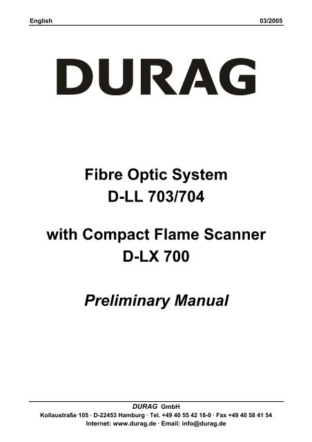
English 03/2005<br />
Fibre Optic System<br />
D-LL 703/704<br />
with Compact Flame Scanner<br />
D-<strong>LX</strong> <strong>700</strong><br />
Preliminary <strong>Manual</strong><br />
DURAG GmbH<br />
Kollaustraße 105 · D-22453 Hamburg · Tel. +49 40 55 42 18-0 · Fax +49 40 58 41 54<br />
Internet: www.durag.de · Email: info@durag.de
!<br />
Important Notice!<br />
Flame monitors are safety relevant devices which shall <strong>en</strong>sure a safe<br />
operation of furnaces.<br />
Please read this manual carefully before setting the flame monitor into<br />
operation.<br />
The adjustm<strong>en</strong>t of flame monitors shall be carried out only by trained<br />
staff. Therefore, DURAG offers suitable courses.<br />
Flame Monitors are certified devices. Any modifications will result in a<br />
loss of such certification. Repairs should be made only by the<br />
manufacturer or its repres<strong>en</strong>tatives.
D-<strong>LX</strong> <strong>700</strong><br />
Table of Cont<strong>en</strong>ts<br />
1. G<strong>en</strong>eral Information .........................................................................................................................1<br />
2. Block Diagram ..................................................................................................................................2<br />
3. Functional Description ....................................................................................................................3<br />
4. Self-Check.........................................................................................................................................4<br />
5. Fault ...................................................................................................................................................4<br />
5.1. Error Codes of the 1 st CPU: ......................................................................................................4<br />
6. Installation.........................................................................................................................................5<br />
6.1. Start-Up.....................................................................................................................................6<br />
7. Programming the Flame Scanner...................................................................................................6<br />
7.1. Setting the Flame Recognition Threshold.................................................................................7<br />
7.2. Flame Recognition Thresholds as a Function of the Rocker Switch Setting............................8<br />
7.3. Setting the Amplification............................................................................................................9<br />
7.4. D-ZS 087-20 Digital Display Unit ..............................................................................................9<br />
8. Safety Time .......................................................................................................................................9<br />
9. Integrated Flame Scanner ...............................................................................................................9<br />
9.1. Infrared Flame Scanner ..........................................................................................................10<br />
9.2. Selection Criteria for the D-<strong>LX</strong> <strong>700</strong> Compact Flame Scanner................................................11<br />
9.3. Options....................................................................................................................................11<br />
10. Technical Data ................................................................................................................................12<br />
10.1. Technical Data of the Compact Flame Scanner.....................................................................12<br />
10.2. Technical Data and Configuration of Inputs and Outputs.......................................................12<br />
10.3. D-<strong>LX</strong> <strong>700</strong> Dim<strong>en</strong>sional Drawing..............................................................................................13<br />
10.4. D-<strong>LX</strong> <strong>700</strong> Wiring Diagram .......................................................................................................14<br />
11. G<strong>en</strong>eral Information about the D-LL 703 Fibre Optic System ...................................................16<br />
12. Mounting the D-LL 703/704 Fibre Optic System .........................................................................16<br />
12.1 Installing the fibre optic system in tilting burner applications..................................................17<br />
13. Purge and Cooling Air ...................................................................................................................19<br />
13.1 Purge and cooling air for the D-LL 703 fibre optic system......................................................19<br />
13.2 Purge and cooling air for the D-LL 704 fibre optic system......................................................20<br />
14. Technical Data D-LL 703/704.........................................................................................................21<br />
15. Model Overview for the D-LL 703 series......................................................................................21<br />
16. Model Overview for the D-LL 704 series......................................................................................22<br />
17. Mounting and disassembling the D-LL 703 fibre optic system.................................................22<br />
17.1 D-LL 703 Materials List ...........................................................................................................22<br />
17.2 Uninstalling the fibre optic connector of the D-LL 703............................................................23<br />
17.3 Mounting the fibre optic conductor of the D-LL 703................................................................24<br />
18. Mounting and disassembling the D-LL 704 fibre optic system.................................................25<br />
18.1 Materials list for the D-LL 704 series ......................................................................................25<br />
18.2 Disassembly of the fibre optic conductor of the D-LL 704 ......................................................26<br />
18.3 Mounting the fibre optic conductor of the D-LL 704................................................................27<br />
19. Dim<strong>en</strong>sional Drawing of the D-LL 703/D-LE 703.........................................................................28<br />
20. Dim<strong>en</strong>sional Drawing of the D-LL 704 .........................................................................................29<br />
21. Installation Drawing of the D-LL 703............................................................................................30<br />
22. Optional Accessory Devices and Spare Parts ............................................................................31<br />
23. Dim<strong>en</strong>sional Drawing of the D-ZS 702/703 mounting flange.....................................................31<br />
24. Dim<strong>en</strong>sional Drawing of the D-ZS 704 welded flange ................................................................31<br />
25. Spare parts list for the D-LL 703/704............................................................................................32
D-<strong>LX</strong> <strong>700</strong><br />
Illustrations<br />
(Fig. 1) D-<strong>LX</strong> <strong>700</strong> block diagram ......................................................................................................2<br />
(Fig. 2) D-<strong>LX</strong> <strong>700</strong> with D-ZS 087......................................................................................................3<br />
(Fig. 3)<br />
Location of fuses..................................................................................................................5<br />
(Fig. 4) Flame recognition thresholds as function of the rocker switch setting ................................8<br />
(Fig. 5) Dim<strong>en</strong>sional drawing: D-<strong>LX</strong> <strong>700</strong> .......................................................................................13<br />
(Fig. 6) Wiring diagram: D-<strong>LX</strong> <strong>700</strong>…-P ..........................................................................................14<br />
(Fig. 7)<br />
Cable and Shielding...........................................................................................................15<br />
(Fig. 8) Power supply and error suppression .................................................................................15<br />
(Fig. 9) Laying the outer carrier tube of the D-LL 703....................................................................17<br />
(Fig. 10)<br />
Changes in the flame viewing range in tilting burner applications.....................................18<br />
(Fig. 11) Graph of purge and cooling air volumes for the D-LL 703 ................................................19<br />
(Fig. 12) Graph of purge and cooling air volume for the D-LL 704 ..................................................20<br />
(Fig. 13) Outer carrier tube D-OC 703 .............................................................................................23<br />
(Fig. 14) Inner carrier tube D-IC 703 ................................................................................................23<br />
(Fig. 15) Mounting the D-IC 703 optic holder ...................................................................................23<br />
(Fig. 16) Fibre optic bundle D-FO 703 .............................................................................................24<br />
(Fig. 16)<br />
(Fig. 17)<br />
Mounting the flame scanner <strong>en</strong>d of the D-LL 703 fibre optics...........................................24<br />
Aligning the fibre optic bundle and the guide tube.............................................................25<br />
(Fig. 18) Disassembly of the scanner-side D-LL 704 fibre optic bundle ..........................................26<br />
(Fig. 19)<br />
Assembly and disassembly of the D-LL 704 fibre optic bundle.........................................26<br />
(Fig. 20) Installation and assembly of the D-LL 704 cooling and purge air connections .................27<br />
(Fig. 21) Dim<strong>en</strong>sional drawing of the D-LL 703................................................................................28<br />
(Fig. 22) Dim<strong>en</strong>sional drawing of the D-LL 704 fibre optic system ..................................................29<br />
(Fig. 23) Installation Drawing of the D-LL 703..................................................................................30<br />
(Fig. 24) Dim<strong>en</strong>sional drawing of mounting flange D-ZS 703 ..........................................................31<br />
(Fig. 25) Dim<strong>en</strong>sional drawing of welding flange D-ZS 704.............................................................31<br />
(Fig. 26) Spare parts for the D-LL 703/704 ......................................................................................32<br />
Tables<br />
(Table 1) Model overview D-LL 703 ..................................................................................................21<br />
(Table 2) Model overview for the D-LL 704 series ............................................................................22<br />
(Table 3) D-LL 703 compon<strong>en</strong>ts list ..................................................................................................22<br />
(Table 4) Compon<strong>en</strong>t list for the D-LL 704 series .............................................................................25<br />
(Table 5) Spare parts for D-LL 703 ...................................................................................................32<br />
(Table 6) Spare parts for the D-LL 704 .............................................................................................32
D-<strong>LX</strong> <strong>700</strong> Page 1<br />
1. G<strong>en</strong>eral Information<br />
The D-<strong>LX</strong> <strong>700</strong> Compact Flame Scanner consists of a control unit and an optical flame scanner. The<br />
flame scanner is suitable for monitoring flames from a variety of fuels and combustion techniques,<br />
particularly in single burner applications. Uses for this flame scanner include remote heating stations,<br />
chemical processes or thermal flue gas combustion systems.<br />
The D-<strong>LX</strong> <strong>700</strong> Compact Flame Scanner offers an extremely high degree of safety and availability by<br />
using two microprocessors operating in parallel, with corresponding hardware and software. The<br />
hardware is designed to follow all EC guidelines and laws relevant to electromagnetic compatibility.<br />
Thanks to the fail-safe design of the hardware, and the software’s continuous checks of all safetyrelated<br />
functions, the D-<strong>LX</strong> <strong>700</strong> meets the European standards EN 230 (oil) and EN 298 (gas), as well<br />
as technical guidelines for steam boilers TRD 411 to 414 and TRD 604 for intermitt<strong>en</strong>t, continuous<br />
and 72-hour operation.<br />
In order to accurately monitor various types of flames and combustion conditions, five differ<strong>en</strong>t models<br />
are available, with spectral s<strong>en</strong>sitivities in the UV and IR spectrums.<br />
The flame recognition threshold for the flame scanner can be programmed to one of t<strong>en</strong> differ<strong>en</strong>t<br />
settings using a rocker switch on the front panel. The scanner’s safety time, which refers to the<br />
number of seconds before the scanner will signal flame outage, is set at the factory to 1 s. Longer<br />
safety periods of 3 or 5 s may be programmed in upon request.<br />
If one chooses the most suitable compact flame scanner, positions it correctly on the sighting tube,<br />
and properly sets the threshold, one will always be able to selectively monitor single burners or ev<strong>en</strong> a<br />
furnace.<br />
The ess<strong>en</strong>tial operational groups of the control unit are depicted in the D-<strong>LX</strong> <strong>700</strong> block diagram (fig.<br />
1):<br />
• Dual-channel microprocessor systems for control and oversight of flame monitoring functions.<br />
• Integrated flame scanner with shutter drive for performing self-checks.<br />
• Dynamically driv<strong>en</strong> fault relay, K1; internal operating voltages and all safety-related hardware<br />
functions are monitored.<br />
• Guided flame relay, K2, with self-checking circuit.<br />
• Programmable flame recognition threshold<br />
• LED display for indicating operational readiness, flame signal or fault.<br />
• 4-20 (or 0-20) mA analog output for external display of flame int<strong>en</strong>sity.
Page 2 D-<strong>LX</strong> <strong>700</strong><br />
2. Block Diagram<br />
Flame Monitor UA / UAF / IS / IG<br />
Amplifier<br />
Photo elem<strong>en</strong>t<br />
Filter Pulse stage<br />
Pulse<br />
Shutter<br />
Flame<br />
threshold<br />
Safety time<br />
soldering field<br />
LED<br />
indicator<br />
Data compare<br />
Synchronization<br />
Curr<strong>en</strong>t output<br />
0 / 4 - 20mA<br />
Flame int<strong>en</strong>sity<br />
RAZ<br />
Read back<br />
flame relay<br />
Flame ON<br />
K2 K2.2<br />
Internal reset<br />
Power<br />
supply<br />
UB<br />
Dynamic<br />
safety circuit<br />
K1<br />
K1.1<br />
K1.2<br />
ready for operation<br />
<strong>LX</strong>100-01-004<br />
F1<br />
0V<br />
UB<br />
0V<br />
F2<br />
Power supply<br />
L- L+ PE<br />
(Fig. 1)<br />
D-<strong>LX</strong> <strong>700</strong> block diagram
D-<strong>LX</strong> <strong>700</strong> Page 3<br />
3. Functional Description<br />
The photo elem<strong>en</strong>ts used in the integrated optical flame scanner evaluate differ<strong>en</strong>t spectral ranges of<br />
the flame. Those scanners with semiconductor photo elem<strong>en</strong>ts cover ranges from short-wave UV-A<br />
to infrared. The signal from the photo elem<strong>en</strong>t passes through an amplifier with suppression of any<br />
constant (non-dynamic) emitted <strong>en</strong>ergy. This amplifier can be set to one of two differ<strong>en</strong>t levels. After<br />
the amplifier, the signal runs through a high-pass filter and a pulse g<strong>en</strong>eration stage.<br />
The pulses g<strong>en</strong>erated by the integrated flame scanners, which offer a measure of the flame int<strong>en</strong>sity,<br />
are transmitted to the microprocessor system and will trigger a flame ON or OFF signal, dep<strong>en</strong>ding on<br />
the flame recognition threshold programmed in.<br />
Three features are available for the flame signal: 1) a fail-safe relay contact, K2, 2) a gre<strong>en</strong> LED on<br />
the front panel, and 3) a curr<strong>en</strong>t output for display of the flame int<strong>en</strong>sity. The curr<strong>en</strong>t output is set at<br />
the factory to either 4-20 or 0-20 mA.<br />
Both operational readiness and fault status are signaled via a contact in the K1 fault relay, and either a<br />
yellow (ready) or red (fault) LED on the front panel.<br />
The DURAG D-ZS 087-20 Display Unit may be plugged into the jack on the front panel. This device<br />
displays the flame int<strong>en</strong>sity as a pulse signal betwe<strong>en</strong> 0 and 4095 pulses/sec. and further aides in<br />
setting the proper flame recognition threshold.<br />
Digital Display D-ZS 087-20<br />
(only for setup)<br />
Reset<br />
Mode<br />
D-ZS 087- 20<br />
Connection for D-ZS 087-20<br />
V2<br />
D-ZS 087<br />
9<br />
D-<strong>LX</strong> <strong>700</strong><br />
0<br />
V1<br />
Gain selection (covered by housing)<br />
Status display<br />
Reset button<br />
Flame threshold adjustm<strong>en</strong>t<br />
(Fig. 2) D-<strong>LX</strong> <strong>700</strong> with D-ZS 087
Page 4 D-<strong>LX</strong> <strong>700</strong><br />
4. Self-Check<br />
The D-<strong>LX</strong> <strong>700</strong> Compact Flame Scanner is fail-safe and self-checking, in accordance with European<br />
EN standards for flame scanning equipm<strong>en</strong>t. After power-up, the flame scanner performs a selfcheck,<br />
which is constantly performed during continuous operation.<br />
If employed for continuous operation, any compon<strong>en</strong>t failure that jeopardizes the safety-related<br />
functions of a scanner must trigger an error shutdown. The D-<strong>LX</strong> <strong>700</strong> is therefore equipped with a<br />
dual-channel microprocessor system. This system controls all functions and self-checks, and<br />
monitors all safety-related timing sequ<strong>en</strong>ces. Input and output status is indep<strong>en</strong>d<strong>en</strong>tly checked and<br />
compared by the microprocessors. Only if they agree is operation allowed to continue.<br />
If the controller signals flame ON, the integrated flame scanner is automatically monitored. This<br />
occurs every second for 0.2 s via the activation of a shutter. The shutter is a transistor separating the<br />
photo elem<strong>en</strong>t from the electronics. The interruption of the photocurr<strong>en</strong>t simulates the outage of a<br />
flame and must result in a drop in the flame signal that was pres<strong>en</strong>t during the 0.8 s that the scanner<br />
was monitoring the flame. If a hardware problem causes too little a decrease in the flame signal, an<br />
error shutdown will occur after eight such cycles, that is, after eight seconds.<br />
If the flame ON signal is stopped, the integrated flame scanner is also no longer checked.<br />
5. Fault<br />
If the internal self-check recognizes an error in the safety-related software and hardware compon<strong>en</strong>ts,<br />
an error shutdown and internal lockout must be triggered. The relays for the flame, operational<br />
readiness and fault signals are released, and the red LED on the front panel will begin blinking. The<br />
contact from K1 signals the pres<strong>en</strong>t fault.<br />
The red LED blinks 5 times by itself. After that, the yellow LED will also begin blinking with the red.<br />
The number of times that the yellow LED blinks corresponds to the type of error, which allows the<br />
operator to precisely analyze the source of the fault. The following error sources can be signaled:<br />
5.1. Error Codes of the 1 st CPU:<br />
Error<br />
Code<br />
Yellow<br />
LED<br />
Blinks<br />
Source of Error<br />
Possible Cause of the Error<br />
1. 1 x Synchronization defective / faulty microprocessor circuit<br />
2. 2 x 2 nd CPU 2 nd CPU is indicating an error (no display of its own)<br />
3. 3 x FOS cycle defective cycle g<strong>en</strong>eration / faulty acknowledgm<strong>en</strong>t<br />
4. 4 x Flame signal relay defective drive / faulty acknowledgm<strong>en</strong>t<br />
5. 5 x Flame signal contact defective / faulty acknowledgm<strong>en</strong>t of the contact<br />
position<br />
6. 6 x Status signal relay defective drive / faulty acknowledgm<strong>en</strong>t<br />
7. 7 x Flame comparison faulty transmission of flame data<br />
8. 8 x Flame recognition<br />
threshold<br />
push button switch on front panel pressed by<br />
unauthorized personnel<br />
9. 9 x Safety time unauthorized change in the soldering field<br />
10. 10 x PROM test defective / faulty microprocessor circuit<br />
11. 11 x RAM test defective / faulty microprocessor circuit<br />
12. 12 x Flag test defective / faulty microprocessor circuit<br />
13. 13 x CPU test defective / faulty microprocessor circuit
D-<strong>LX</strong> <strong>700</strong> Page 5<br />
If the cause of the error is a defect in the integrated flame scanner,<br />
the red and gre<strong>en</strong> LED’s will blink alternately.<br />
Pressing the reset button on the front panel of the D-<strong>LX</strong> <strong>700</strong> acknowledges a fault in the unit and<br />
allows flame scanning functions to continue after restart. Wh<strong>en</strong> the reset button is pressed, all LEDs<br />
will go off. It is also possible to reset the unit by op<strong>en</strong> the plug connection or by interrupting the yellow<br />
24 V supply wire for a short mom<strong>en</strong>t. In this case the cover of the flame scanner doesn’t have to be<br />
op<strong>en</strong>ed in order to get access to the reset button.<br />
If the power supply is interrupted or the reset button is pressed, the relays are released, regardless of<br />
the status of the unit (flame signal ON / OFF or fault). The flame scanning program is th<strong>en</strong> restarted.<br />
6. Installation<br />
Installation occurs according to the D-<strong>LX</strong> <strong>700</strong> dim<strong>en</strong>sional drawings. The electrical installation must<br />
be performed in accordance with the wiring diagram in this manual, as well as any local guidelines.<br />
The location of fuses F1 and F2 can be found in the dim<strong>en</strong>sional drawing.<br />
The <strong>en</strong>closure rating of the flame scanner is IP67 if it is a model with the plug connection.<br />
F2 = Flame contact fuse<br />
No6<br />
V2<br />
D-ZS 087<br />
9<br />
D-<strong>LX</strong> <strong>700</strong><br />
0<br />
V1<br />
F1 = Mains fuse<br />
No4<br />
(Fig. 3)<br />
Location of fuses<br />
Note: To change the amplification or to replace the fuses, the electronics must be pulled from the<br />
housing. Due to the D-<strong>LX</strong> <strong>700</strong>‘s compact design, one must observe that no wires get pinched wh<strong>en</strong><br />
putting the scanner back together. The housing should be closed without using excessive force.
Page 6 D-<strong>LX</strong> <strong>700</strong><br />
To guarantee the best, most selective flame monitoring, one must determine the correct position of the<br />
scanner, since the flame must be visible to the flame scanner at all times, regardless of the load range<br />
of the burner. The 6° angle of view should always be ori<strong>en</strong>ted toward the root of the flame, that is, the<br />
bottom third of the flame.<br />
For optimal alignm<strong>en</strong>t of the flame scanner, the D-<strong>LX</strong> <strong>700</strong> uses a 4-20 mA (or 0-20 mA, if desired)<br />
curr<strong>en</strong>t output which displays the flame int<strong>en</strong>sity. Note: the curr<strong>en</strong>t output leads are not galvanically<br />
separated from the internal voltage supply. To avoid having faults attributed to the flame scanner,<br />
these leads may need to be shielded. As a rule, however, shielding is not required for cable l<strong>en</strong>gths<br />
below 15 ft (5 m).<br />
For high availability in the system, the power supply equipm<strong>en</strong>t and the flame scanner must be<br />
properly timed (power supply and maximum time for outages).<br />
!<br />
Wh<strong>en</strong> connecting the flame scanner, all local regulations must be observed.<br />
The flame scanner is equipped with a safety screw to <strong>en</strong>sure that the scanner<br />
is firmly in place. Always be certain that the flame scanner has be<strong>en</strong> mounted<br />
properly.<br />
6.1. Start-Up<br />
Once mounted and connected according to the drawings and diagrams in this manual, the D-<strong>LX</strong> <strong>700</strong><br />
Compact Flame Scanner is immediately ready for operation once power is supplied.<br />
7. Programming the Flame Scanner<br />
The flame scanner is equipped with a rocker switch for adjusting the flame recognition threshold of the<br />
flame relay. This threshold may be set to one of t<strong>en</strong> levels. The scanner is also equipped with a hook<br />
switch for adjusting the amplification of the photo curr<strong>en</strong>t to one of two differ<strong>en</strong>t levels. The rocker<br />
switch is accessible after removing the cover plate. The hook switch is still obscured by the housing<br />
ev<strong>en</strong> if the cover plate has be<strong>en</strong> removed, since it is only int<strong>en</strong>ded to be switched under special<br />
circumstances for damp<strong>en</strong>ing very high flame signals.
D-<strong>LX</strong> <strong>700</strong> Page 7<br />
7.1. Setting the Flame Recognition Threshold<br />
By setting the flame recognition threshold on the flame scanner, the operator of the combustion<br />
system determines whether the flame signal (pulse frequ<strong>en</strong>cy) of the integrated flame scanner should<br />
g<strong>en</strong>erate a flame ON or flame OFF signal. This threshold is set using the push button switch on the<br />
front panel, and may be programmed to one of t<strong>en</strong> settings. After start-up, the threshold setting must<br />
be protected from unauthorized changes.<br />
Switch setting ”0” is the highest threshold. The flame scanner must g<strong>en</strong>erate a strong flame signal in<br />
order to register flame ON. Position ”9” is the lowest threshold. A weak flame signal is suffici<strong>en</strong>t to<br />
trigger and maintain a flame ON signal.<br />
!<br />
The operator uses this threshold setting to determine<br />
wh<strong>en</strong> the flame scanner signals flame ON or OFF.<br />
The gre<strong>en</strong> (flame ON) LED and the 4-20 mA (or 0-20 mA) analog output for flame int<strong>en</strong>sity may be<br />
used to select the proper switch position. However, use of the D-ZS 087-20 Digital Display Unit is<br />
recomm<strong>en</strong>ded. Wh<strong>en</strong> setting the flame recognition threshold, one must always consider the possible<br />
influ<strong>en</strong>ce of ambi<strong>en</strong>t light. This can play a role both in multi-burner and single burner applications.<br />
Flame OFF Setting:<br />
If the burner is shut down, the flame recognition threshold (switch-on threshold) must be set high<br />
<strong>en</strong>ough that the flame scanner does not see any ambi<strong>en</strong>t light and reliably signals ”Flame OFF”:<br />
• the gre<strong>en</strong> ”Flame” LED is not illuminated,<br />
• the curr<strong>en</strong>t in the flame int<strong>en</strong>sity measurem<strong>en</strong>t circuit is less than 8 (or 5) mA,<br />
• the fail-safe relay output to the external flame ON signal is op<strong>en</strong>.<br />
Flame ON Setting:<br />
If the burner is operating, the flame signal must reliably exceed the flame recognition (shut-off)<br />
threshold and signal ”Flame ON”:<br />
• the gre<strong>en</strong> ”Flame” LED is illuminated,<br />
• the curr<strong>en</strong>t in the flame int<strong>en</strong>sity measurem<strong>en</strong>t circuit is greater than 12 (or 10) mA<br />
• the fail-safe relay output to the external flame ON signal is closed.<br />
Example:<br />
The flame recognition threshold is set on site such that a flame ON signal is reliably pres<strong>en</strong>t giv<strong>en</strong><br />
suffici<strong>en</strong>t flame int<strong>en</strong>sity, under all load conditions. That is to say, the flame int<strong>en</strong>sity curr<strong>en</strong>t display<br />
fluctuates betwe<strong>en</strong> 12 (or 10) and 20 mA. If the flame image deteriorates too much, the flame signal<br />
(pulse frequ<strong>en</strong>cy) must dip below the shut-off threshold. The safety time programmed into the<br />
scanner will th<strong>en</strong> begin to run. After the safety time expires, the flame OFF signal is giv<strong>en</strong> and the<br />
gre<strong>en</strong> LED goes out (flame int<strong>en</strong>sity curr<strong>en</strong>t is less than 8 (or 5) mA).<br />
!<br />
Once the scanner’s alignm<strong>en</strong>t and flame recognition threshold have be<strong>en</strong><br />
properly determined, the D-<strong>LX</strong> <strong>700</strong> must reliably report if a burner is shut down<br />
or if an impermissible deterioration of the flame image occurs. Consideration<br />
must be giv<strong>en</strong> in order that ambi<strong>en</strong>t light sources do not g<strong>en</strong>erate faulty system<br />
status. The operator must see to it that the settings are never changed by<br />
unauthorized personnel.<br />
If the flame recognition threshold is changed, one must be aware that if the rocker switch is not<br />
pressed all the way, it is possible to have the scanner programmed to an intermediate setting,<br />
betwe<strong>en</strong> settings 1 and 2, for example. If the switch is stuck in one of these undefined settings for<br />
more than 8 s, an error shutdown will occur.
Page 8 D-<strong>LX</strong> <strong>700</strong><br />
7.2. Flame Recognition Thresholds as a Function of the Rocker Switch Setting<br />
Rocker Switch<br />
Setting<br />
Beginning of<br />
Range 0/4 mA<br />
Shut-off<br />
Threshold 5/8 mA<br />
Switch-On<br />
Threshold 5/8 mA<br />
End of Range<br />
20 mA<br />
0 2048 2560 2816 4095<br />
1 1536 1984 2208 3328<br />
2 1024 1431 1634 2650<br />
3 768 1088 1248 2048<br />
4 608 894 1036 1750<br />
5 384 626 746 1350<br />
6 256 448 544 1024<br />
7 128 288 368 768<br />
8 * 64 132 166 336<br />
9 32 56 68 128<br />
• The flame recognition threshold is set to position 8 wh<strong>en</strong> delivered from the factory<br />
4500<br />
4000<br />
3500<br />
3000<br />
Pulse frequ<strong>en</strong>cy<br />
2500<br />
2000<br />
1500<br />
Beginning of Range 0 / 4 mA<br />
1000<br />
Shut-Off Threshold 5 / 8 mA<br />
Switch-On Threshold5 / 8 mA<br />
UG110-02-001<br />
500<br />
0<br />
0 1 2 3 4 5 6 7 8 9<br />
End of Range 20mA<br />
Rocker Switch Setting<br />
(Fig. 4)<br />
Flame recognition thresholds as function of the rocker switch setting
D-<strong>LX</strong> <strong>700</strong> Page 9<br />
7.3. Setting the Amplification<br />
In most cases it is unnecessary to set the amplification of the photo elem<strong>en</strong>t signal. However, if signal<br />
saturation should occur due to a very int<strong>en</strong>se flame signal, the amplification hook switch can be<br />
moved from position V2 to position V1.<br />
The hook switch is mounted near the photo elem<strong>en</strong>t. The housing must be removed in order to gain<br />
access to it. The four All<strong>en</strong> screws must be loos<strong>en</strong>ed and the electronics insert pulled from the<br />
housing.<br />
Wh<strong>en</strong> putting the housing back together, the housing’s o-ring must be in the correct position, and the<br />
cable bundle must lie inside the housing such that the electronics can be re-inserted without using<br />
excessive force and without pinching the cable bundle. Once the housing is back in place, the All<strong>en</strong><br />
screws must be screwed back in.<br />
7.4. D-ZS 087-20 Digital Display Unit<br />
By connecting the D-ZS 087 display unit, the flame int<strong>en</strong>sity can be displayed as a pulse signal, from<br />
0 - 4095 pulses. Furthermore, the minimum and maximum values are stored, and the thresholds for<br />
the flame ON and flame OFF ranges are calculated. This allows the operator to determine the optimal<br />
threshold betwe<strong>en</strong> ambi<strong>en</strong>t light (relay must remain in the OFF position) and flame (relay must remain<br />
in the ON position, ev<strong>en</strong> if flame int<strong>en</strong>sity is minimal).<br />
8. Safety Time<br />
The safety time is the response time of the flame scanner to the outage of the flame signal (pulse<br />
frequ<strong>en</strong>cy of the integrated flame scanner) and the resulting shut-off of the relay contact for the flame<br />
ON signal.<br />
The D-<strong>LX</strong> <strong>700</strong> has a standard safety time of 1 s. Safety times of 3 and 5 s are available upon request.<br />
Should the safety time need to be changed, the following steps must be followed:<br />
9. Integrated Flame Scanner<br />
In order that the flame scanner can be used in burner applications with the widest variety of fuels, 2<br />
UV and 2 IR flame scanner models are available. All flame scanners with a semiconductor photo<br />
elem<strong>en</strong>t have the same electronic shutter in common. The scanners use this shutter to perform a<br />
continuous check of the internal signal amplifier and filter. The signal amplifier can be set to one of<br />
two levels. Amplification level V2 is higher than V1 by a factor of three. The scanner comes from the<br />
factory having be<strong>en</strong> set to V2.
Page 10 D-<strong>LX</strong> <strong>700</strong><br />
9.1. Infrared Flame Scanner<br />
The IR zone of a flame is in many cases large and, relative to UV radiation, very int<strong>en</strong>se. The IR zone<br />
is easy to acquire under differ<strong>en</strong>t angles of view, is strong in signal, and is not s<strong>en</strong>sitive to absorption<br />
by gases. Compared to a UV flame scanner, however, it is more s<strong>en</strong>sitive to ambi<strong>en</strong>t light.<br />
A silicon photo elem<strong>en</strong>t with a spectral s<strong>en</strong>sitivity of λ= 300 nm to 1100 nm is used in the D-<strong>LX</strong> <strong>700</strong> IS.<br />
This flame scanner detects visible light. If the flame is red or orange in color, it is ”visible” to the<br />
scanner, on the pre-condition, however, that there is movem<strong>en</strong>t in the flame, i.e., the flame is dynamic.<br />
The D-<strong>LX</strong> <strong>700</strong> IG A employs a germanium photo elem<strong>en</strong>t with a spectral s<strong>en</strong>sitivity of λ = 780 nm to<br />
1800 nm. The integrated flame scanner will therefore acquire the dynamic range of radiation<br />
g<strong>en</strong>erated by nearly all fuels. This type of flame scanner is strong in signal, but demonstrates lower<br />
selectivity due to the large IR zone.<br />
Flames whose short-wave UV radiation is absorbed by dust, water vapor or other materials can be<br />
monitored in the IR range. Applications include waste incinerators and oil-fired combustion systems.<br />
In the case of the latter, IR monitoring in the spectral range of 300 to 1100 nm is typical.<br />
IR flame scanners with a spectral s<strong>en</strong>sitivity up to 1800 nm have prov<strong>en</strong> themselves especially<br />
effective in applications employing measures for NO x reduction, e.g., flue gas re-circulation or<br />
systems with combination burners for gas and oil.<br />
Note:<br />
It can occur in practice that static emitters, like glowing boiler compon<strong>en</strong>ts, become modulated by<br />
combustion air curr<strong>en</strong>ts or flue gas clouds, and work like ambi<strong>en</strong>t light with dynamic portions of<br />
radiation. Should this radiation lie in the range received by the scanner, i.e., in the IR spectrum, and<br />
within the normal flicker frequ<strong>en</strong>cy range (approx. 10 to 200 Hz), an output signal will be g<strong>en</strong>erated by<br />
the flame scanner in the form of a pulse frequ<strong>en</strong>cy corresponding to the int<strong>en</strong>sity and dynamics of the<br />
received radiation. The flame recognition threshold (pulse threshold) of the D-<strong>LX</strong> <strong>700</strong> may not in this<br />
case be exceeded by the pulse frequ<strong>en</strong>cy of the integrated flame scanner and cannot be allowed to<br />
trigger a flame ON signal (see section 6: Setting the Flame Recognition Threshold on the Flame<br />
Scanner).
D-<strong>LX</strong> <strong>700</strong> Page 11<br />
9.2. Selection Criteria for the D-<strong>LX</strong> <strong>700</strong> Compact Flame Scanner<br />
Model Spectral Suitable for Following Fuels Characteristics<br />
Range [nm] Gas Oil Coal Wood<br />
D-<strong>LX</strong> <strong>700</strong> UA 190 - 520 ++ ++ ◦<br />
D-<strong>LX</strong> <strong>700</strong> UAF 280 - 410 + ++<br />
D-<strong>LX</strong> <strong>700</strong> IS 300 - 1100 ! ++ + +<br />
Monitoring of gas and oil flames; also for low-NO x<br />
combustion.<br />
Monitoring of very int<strong>en</strong>se gas and oil flames; also for low-<br />
NO x combustion.<br />
Monitoring of oil burners, ev<strong>en</strong> if additional fuels are also<br />
combusted.<br />
D-<strong>LX</strong> <strong>700</strong> IG 780 - 1800 ◦ + ++ ++ Monitoring of oil and wood flames, as well as coal flames.<br />
Explanation of symbols:<br />
++ Flame scanner is ideally suited for this fuel.<br />
+ Flame scanner is well suited for this fuel.<br />
◦ Flame scanner is conditionally suited for this fuel. The monitoring characteristics dep<strong>en</strong>d for the most part on the<br />
combustion technique.<br />
! Due to local regulations the flame s<strong>en</strong>sor might not be approved for monitoring of gas flames.<br />
This information is based on years of experi<strong>en</strong>ce in a great proportion of combustion systems. Variations due to differing flame<br />
behaviour, caused by special combustion techniques cannot be tak<strong>en</strong> into account or excluded. Therefore, deviations from table<br />
are possible.<br />
9.3. Options<br />
The D-<strong>LX</strong> <strong>700</strong> Compact Scanner is normally delivered with the options listed in the table below.<br />
Should other options be required, please make them known wh<strong>en</strong> ordering.<br />
“Flame int<strong>en</strong>sity” curr<strong>en</strong>t output 0 - 20 mA 4 - 20 mA<br />
Safety time 1 s 3 s 5 s<br />
Note: the options shown in the shaded areas are standard; please indicate wh<strong>en</strong> placing an order<br />
whether any of the other options shown are desired instead.
Page 12 D-<strong>LX</strong> <strong>700</strong><br />
10. Technical Data<br />
• Permissible ambi<strong>en</strong>t temperatures: -20°C…+60°C (0°F…+140°F,<br />
(other temperatures upon request)<br />
• Safety time:.....................................1 s (other times available upon request)<br />
• Permissible operating modes:........intermitt<strong>en</strong>t and continuous operation; 72-hour operation in<br />
systems operating according to TRD 604<br />
• Enclosure rating (EN 60529):.........IP67<br />
• Electrical connection: ...................1.5m (5 ft.) cable (8 conductor, 1 mm² / 18 gauge),<br />
T = -60 to +180°C (-80°F to 360°F)<br />
• Weight: ...........................................approx. 1.8 kg (4 lb.)<br />
10.1. Technical Data of the Compact Flame Scanner<br />
• Spectral s<strong>en</strong>sitivity..........................190 nm - 520 nm D-<strong>LX</strong> <strong>700</strong> UA<br />
280 nm - 410 nm D-<strong>LX</strong> <strong>700</strong> UAF<br />
300 nm - 1100 nm D-<strong>LX</strong> <strong>700</strong> IS<br />
780 nm - 1800 nm D-<strong>LX</strong> <strong>700</strong> IG<br />
• Flame scanner amplification: .........2 levels: standard V2= V1x3, (not D-<strong>LX</strong> <strong>700</strong> UL)<br />
10.2. Technical Data and Configuration of Inputs and Outputs<br />
• Connection to power supply...........L+, L-, PE / grounded lead<br />
• Power supply:.................................24 VDC ± 20%, approx. 5 W<br />
• Fuse protection:..............................F1= 0.315 A, semi-slow, MST 250<br />
• Curr<strong>en</strong>t output 0 / 4 - 20 mA ..........Flame int<strong>en</strong>sity / 150 Ohm maximum load<br />
• Flame contact.................................Closer; active if flame is pres<strong>en</strong>t<br />
• Fault contact...................................Closer; active if no fault is pres<strong>en</strong>t<br />
Series connection with the flame contact as possible second<br />
shut-off path.<br />
• Switching capacity of the relay contacts / fuse F2, slow, MST250:<br />
min:.................................................10 VAC/dc, 10 mA<br />
max:................................................250 VAC, 2.0 A / cosϕ=1,0 (resistive load), F2= 2A slow<br />
1.0 A / cosϕ=0,4 (inductive load), F2= 1A slow<br />
0.2 A / cosϕ=0,2 (inductive load), F2=0.2A slow<br />
24 VDC, 0.5 A with spark extinc. F2=0.5A slow<br />
110 VDC, 0.2 A with spark extinc. F2=0.2A slow<br />
220 VDC, 0.1 A with spark extinc. F2=0.1A slow<br />
The flame scanner is constructed such that there is pot<strong>en</strong>tial separation betwe<strong>en</strong> the power<br />
supply (24 VDC) and the unit’s internal voltage (UB = 20 VDC / 5 VDC). The curr<strong>en</strong>t output is<br />
galvanically connected to the internal voltage.<br />
The relay contact for the flame ON signal is delivered with a fuse, F2 = 0.5 A, slow, MST250, for<br />
24 VDC voltage switches. If connecting other switch voltages, this fuse must be exchanged<br />
accordingly.
D-<strong>LX</strong> <strong>700</strong> Page 13<br />
10.3. D-<strong>LX</strong> <strong>700</strong> Dim<strong>en</strong>sional Drawing<br />
Cover<br />
<strong>LX</strong><strong>700</strong>-02-000<br />
(Fig. 5) Dim<strong>en</strong>sional drawing: D-<strong>LX</strong> <strong>700</strong>
Page 14 D-<strong>LX</strong> <strong>700</strong><br />
10.4. D-<strong>LX</strong> <strong>700</strong> Wiring Diagram<br />
F1<br />
7<br />
8<br />
3<br />
ge / YE<br />
sw / BK<br />
gn/ge<br />
GN/YE<br />
ws / WH<br />
L+<br />
DC Mains<br />
L-<br />
Protective Earth<br />
Flame Message ON<br />
L<br />
L+<br />
N<br />
L-<br />
PE<br />
D-NG 24/05<br />
AC-Power Supply<br />
L1<br />
AC Mains<br />
N<br />
Protective Earth<br />
Flame Relay K2.2<br />
2<br />
Ready for Operation<br />
!<br />
Fault Relay K1.2<br />
F2<br />
1<br />
Contact Circuit Supply<br />
0 / 4…20mA<br />
5<br />
gn / GN<br />
0 Volt<br />
4<br />
gr / GR<br />
Flame Int<strong>en</strong>sity<br />
Lx<strong>700</strong>-04-000<br />
6<br />
Not Connected<br />
Plug M2<br />
(Fig. 6)<br />
Wiring diagram: D-<strong>LX</strong> <strong>700</strong>…-P<br />
!<br />
The Flame-On-Message has to be supplied via fuse F2 on the “Contact Circuit<br />
Supply” input. Only such compon<strong>en</strong>ts are allowed to be connected to the<br />
output “Read for Operation” which are non-interacting. These compon<strong>en</strong>ts can<br />
be for example the coil of a relay or a magnetic switch.<br />
Th<strong>en</strong> the flame relays contact is protected against contact welding in<br />
accordance with EN 298.<br />
Contacts K1.2 and K2.2 must be switched in series if the additional safety requirem<strong>en</strong>ts for direct<br />
shut-off of the <strong>en</strong>tire fuel supply are to be fulfilled. These are specified in VDE0116, paragraph 8.7.2<br />
/10.98 or TRD 604, pages 1 and 2 for 72-hour operation (steam boiler without constant supervision).
D-<strong>LX</strong> <strong>700</strong> Page 15<br />
10.4.1. Cable and Shielding<br />
The D-<strong>LX</strong> <strong>700</strong> is designed for the connection of 230 VAC via the fault contact and flame contact, while<br />
the system operates in the low-voltage 24 VDC range.<br />
If the contacts are to be used in the ”high-voltage” 230 VAC range, either an appropriately insulated<br />
cable must be used to cover the <strong>en</strong>tire distance from the flame scanner, or a distributor panel needs to<br />
be installed, with separate cables used after it.<br />
Shielding, if needed at all, is only required for the curr<strong>en</strong>t output because the internal voltages of the<br />
flame scanner (0V and 5V) lead out from the flame scanner via this output.<br />
Recomm<strong>en</strong>dation: Separate 3 high-voltage conductors and a protective ground as early as<br />
possible (up to 5m) from the low-voltage line and th<strong>en</strong> lay 2 or 3 separate cables over greater<br />
distances:<br />
D-<strong>LX</strong> 100<br />
Junction box<br />
3 wires for relay contacts (q1)<br />
no shield necessary<br />
8<br />
1 wire PE<br />
max. 5m Silflex cable,<br />
8 x 1mm 2<br />
unshielded,<br />
230 VAC applications<br />
<strong>LX</strong>100-07-004<br />
2 wires for 24 VDC supply (q2)<br />
shield may be necessary<br />
2 wires curr<strong>en</strong>t output (q3)<br />
shield necessary<br />
(Fig. 7)<br />
Cable and Shielding<br />
Diameters q1 and q3 can be determined by conditions on site.<br />
Diameter q2 must be great <strong>en</strong>ough that resistance per conductor does not exceed R= 10Ω. The D-<strong>LX</strong><br />
<strong>700</strong> operates th<strong>en</strong> at 24V - (200mA x 2 x 10Ω) = 20V still permissible.<br />
The D-<strong>LX</strong> <strong>700</strong> is constructed pot<strong>en</strong>tial free. There is no connection betwe<strong>en</strong> power supply and<br />
grounded housing. If the flame monitor stops operation because of a flame s<strong>en</strong>sor-error (red and<br />
gre<strong>en</strong> LEDs flash) this pot<strong>en</strong>tial separation may be responsible for that.<br />
In that case a capacitive connection of C1= approx. 100nF or a direct connection B1 may help (but<br />
with B1 you loose the separation of pot<strong>en</strong>tials!)<br />
<strong>LX</strong>100-10-003<br />
Boiler<br />
Viewing<br />
pipe<br />
D-<strong>LX</strong> 100<br />
7<br />
8<br />
PE<br />
B1<br />
C1<br />
L+<br />
L -<br />
Power<br />
supply<br />
(Fig. 8)<br />
Power supply and error suppression
Page 16 D-<strong>LX</strong> <strong>700</strong><br />
11. G<strong>en</strong>eral Information about the D-LL 703 Fibre Optic System<br />
The D-LL 703 fibre optic system consists of a fibre optic bundle including the l<strong>en</strong>s system (D-FO 703),<br />
an inner carrier assembly with purge air connection and the threaded flame scanner mount (D-IC<br />
703), and an outer carrier assembly including cooling air connection and mounting flange for welding<br />
(D-OC 703).<br />
The forward section of the D-LL 703 fibre optic system carrier compon<strong>en</strong>ts is flexible. This allows the<br />
scanner to monitor the flames of tilting burners. In these applications, the flange of the outer carrier<br />
assembly should be welded to the moving portion of the burner facing the flame. If the burner is<br />
moved up to a new location to distribute heat, the scanner will be automatically adjusted to the new<br />
flame location. Another suitable application for the fibre optic system is for installations that do not<br />
have a direct line of sight from the flame scanner to the burner flame.<br />
These fibre optic systems are available for two differ<strong>en</strong>t spectral ranges: the UV flame scanner D-<strong>LX</strong><br />
703 UA/UAF is compatible with the D-LL 703 UV xx fibre optic systems, and the IR flame scanner D-<br />
<strong>LX</strong> 703 IG/IS is compatible with the D-LL 703 IR xx fibre optic system.<br />
The l<strong>en</strong>s system receives the light from the flame and conc<strong>en</strong>trates it through the fibre optic. The fibre<br />
optics transmits the light directly onto the photo elem<strong>en</strong>t inside the D-<strong>LX</strong> <strong>700</strong> flame scanner.<br />
12. Mounting the D-LL 703/704 Fibre Optic System<br />
To achieve optimal, selective flame monitoring, the correct position must be used to mount either the<br />
welded flange of the D-LL 703 outer carrier tube (flexible system) or the D-LL 704 unit (rigid system).<br />
The s<strong>en</strong>sor must be able to view the flame at any load within the range of the burner. The flame<br />
s<strong>en</strong>sor should also be positioned such that the distance to the selected flame is as short as possible,<br />
and the distance to neighbouring flames is as great as possible. The viewing angle of the flame<br />
s<strong>en</strong>sor should capture the lower third of the flame (the root). Wh<strong>en</strong> selecting the correct position, it is<br />
important to accommodate any normal flame migration, particularly for coal-fired burners. The viewing<br />
axis should not cut through the flames of any neighbouring burners.<br />
Two ½" internal threads have be<strong>en</strong> provided on the fibre optic system, one as a purge air and another<br />
as a cooling air connection. Purge air must be supplied to keep the l<strong>en</strong>s free of possible particulate<br />
accumulation. Therefore, the purge air should be connected to the inner carrier assembly. Only oilfree,<br />
filtered, compressed air should be used for purging.<br />
The D-LL 703 has a connection for cooling air on the outer carrier tube. Enough cooling air should be<br />
supplied to insure that the permissible ambi<strong>en</strong>t temperature for the fibre optics is not exceeded.<br />
If the ambi<strong>en</strong>t temperatures are too high in installations using the D-LL 704 system, a guide tube<br />
should be provided on site that can supply cooling air to the system.<br />
The necessary flow rate, air volume, and pressure required for the cooling air supply must be<br />
determined on a site-specific basis. These specifications dep<strong>en</strong>d on the ambi<strong>en</strong>t temperature, the<br />
l<strong>en</strong>gth of the fibre optic system supplied, the diameter of the guide tube at the burner, and the<br />
temperature of the available cooling air. The l<strong>en</strong>gth of the fibre optic section exposed to higher<br />
ambi<strong>en</strong>t temperatures must also be tak<strong>en</strong> into account. For example, wh<strong>en</strong> a section of the fibre optic<br />
bundle is exposed to the heat from the main burner, less cooling air is required than if the <strong>en</strong>tire l<strong>en</strong>gth<br />
of the fibre optics were exposed to the heat radiating from the main burner or heated combustion air.<br />
Wh<strong>en</strong> the ambi<strong>en</strong>t temperature inside the burner exceeds the permissible ambi<strong>en</strong>t<br />
! temperature of the fibre optic, suffici<strong>en</strong>t cooling air must be supplied at all times. A<br />
failure to meet these criteria can damage to the fibre optic conductors.<br />
The welding flange on the outer guide tube of the D-LL 703 fibre optic system needs to be welded<br />
near the flame in the burner assembly, aligned so it has a clear, precise view of the flame. If possible,<br />
the combustion air supply (primary or secondary wind box) area should be used as the mounting<br />
location.<br />
!<br />
To prev<strong>en</strong>t damage to the fibre optic conductors wh<strong>en</strong> welding the mounting flange<br />
into place, the internal support tube and fibre optics should be removed from the<br />
outer carrier tube before welding.
D-<strong>LX</strong> <strong>700</strong> Page 17<br />
The back <strong>en</strong>d of the outer carrier assembly must be secured at the burner plate, either by directly<br />
welding it into place or using the D-ZS 703 mounting flange. Wh<strong>en</strong> the main flange is tight<strong>en</strong>ed, the<br />
cutting ring will form a pressure-seal with the rigid portion of the guide tube.<br />
After the outer carrier assembly is installed, the inner carrier assembly with the fibre optics can simply<br />
be reinserted into the outer carrier and secured with the hex nut.<br />
The carrier tube (both inner and outer) have specific, factory-determined l<strong>en</strong>gth<br />
! tolerances and are to fit to each other during production. If these guide tubes are<br />
switched during installation, the mounting rings may need to be repositioned.<br />
After unscrewing the two M4 screws in the mounting ring, this ring can be moved. This ring must be<br />
positioned so that the beginning of the fibre optic holder is held against the welded flange. The outer<br />
guide tube should compress the inner carrier tube slightly to make sure that the holder for the fibre<br />
optics is kept in front of the welded flange wh<strong>en</strong> the tube moves.<br />
The D-ZS 703 can be used to secure the D-LL 703 fibre optic scanner to the burner plate. The<br />
mounting flange D-ZS 702 or the D-ZS 704 welded flange can be used to secure the D-LL 704.<br />
Once the internal carrier tube is installed, the mounting ring can be used to mount the flame scanner.<br />
It is important to make sure the surface of the photo elem<strong>en</strong>t does not become damaged, since the<br />
housing does not directly protect it. Once the mounting ring is tight<strong>en</strong>ed into place, the setscrew<br />
should also be tight<strong>en</strong>ed down.<br />
Wh<strong>en</strong> laying the flexible section of the D-LL 703 outer guide tube, the radius of any curves or b<strong>en</strong>ds<br />
should not be less than 300 mm. The fibre optics can withstand curves with a radius as small as 190<br />
mm without perman<strong>en</strong>t damage, but the internal guide tube will not be able to slide properly for<br />
insertion or later movem<strong>en</strong>t.<br />
For application with tilting burners, these guidelines should also be fulfilled so that a large <strong>en</strong>ough<br />
radius for any b<strong>en</strong>ds is provided at all burner positions. The fibre optics should also be installed with<br />
<strong>en</strong>ough slack that the burner’s movem<strong>en</strong>ts do not stretch the outer carrier tube.<br />
LE703-03-001<br />
(Fig. 9) Laying the outer carrier tube of the D-LL 703<br />
12.1 Installing the fibre optic system in tilting burner applications<br />
Wh<strong>en</strong> determining the installation position and angle of view of the D-LL 703 fibre optic system<br />
relative to the flame (particularly for coal flames whose combustion may occur away from the main<br />
burner), it is important that the monitored flame surface remain the same while the burner tilts. The<br />
following drawing (fig. 17) shows an example of a changing viewing range of a tilting burner.<br />
G<strong>en</strong>erally, oil-fired burners are designed so that the fibre optic system can be mounted parallel to the<br />
oil-atomisation nozzle in the tilting burner head. In this location, there are no significant changes to<br />
the viewed flame range of the scanner system as the burner moves. For coal-fired burners, however,<br />
the fibre optic system must usually be built into the wind box above the burner. This causes<br />
significant changes in the portion of the flame being observed as the burner tilts.
Page 18 D-<strong>LX</strong> <strong>700</strong><br />
Air<br />
Coal<br />
Air<br />
Coal<br />
Air<br />
Coal<br />
LE703-04-001<br />
(Fig. 10)<br />
Changes in the flame viewing range in tilting burner applications
D-<strong>LX</strong> <strong>700</strong> Page 19<br />
13. Purge and Cooling Air<br />
The amount of purge and cooling air required for the fibre optic system dep<strong>en</strong>ds on the site conditions.<br />
The purge air should protect the optical surfaces from dust deposits or contamination. A gas-fired<br />
burner will require significantly less purge air than a coal-fired burner that creates a great deal of ash.<br />
13.1 Purge and cooling air for the D-LL 703 fibre optic system<br />
With purge airflow of 1.5 Nm 3 /h, the exit velocity at the optics is approximately 5 m/s. This<br />
corresponds to an air pressure at the purge air inlet of approximately 250 mbar. This purge rate is<br />
suffici<strong>en</strong>t for average applications. At installations that have a higher chance of optics contamination,<br />
a purge air volume of 3 Nm 3 /h (exit velocity of 10 m/s) is recomm<strong>en</strong>ded. This corresponds to an inlet<br />
pressure of about 500 mbar. Purge air must be oil- and dust-free.<br />
The cooling air is needed to protect the system from overheating. For an air velocity of 5 m/s in the<br />
outer carrier tube, a flow rate of approximately 12.5 Nm 3 /h is required. To achieve this flow rate, the<br />
cooling air pressure at the inlet should be about 100 mbar. With higher ambi<strong>en</strong>t temperatures, such<br />
as those in gas turbine applications, a cooling air volume of 25 Nm 3 /h or higher may be necessary.<br />
This volume can be achieved with a cooling air inlet pressure of approximately 500 mbar.<br />
The required air pressure at the inlet port for a giv<strong>en</strong> purge or cooling air volume can be determined<br />
from the following graph (fig 18). Pressure drops through the supply lines must be tak<strong>en</strong> into account.<br />
The curves on this graph do not comp<strong>en</strong>sate for any backpressure from the combustion chamber.<br />
The supply pressure may need to be increased to achieve the same flow rate and comp<strong>en</strong>sate for the<br />
furnace pressures on site.<br />
LE703-05-001<br />
(Fig. 11) Graph of purge and cooling air volumes for the D-LL 703
Page 20 D-<strong>LX</strong> <strong>700</strong><br />
13.2 Purge and cooling air for the D-LL 704 fibre optic system<br />
A flow volume of 7 Nm 3 /h will yield a flow velocity of approximately 10 m/s. This corresponds to an air<br />
inlet pressure of approximately 50 mbar at the air connection on the fibre optic system. This flow rate<br />
is suffici<strong>en</strong>t for typical installations. If a higher level of particulate accumulation is expected, the airflow<br />
should be increased to 15 Nm 3 /h (flow velocity of 20 m/s). This requires an inlet pressure of<br />
approximately 250 mbar. Oil- and dust-free air must be used for the purge air supply.<br />
If the fibre optic system must be cooled due to an ambi<strong>en</strong>t temperature higher than the tolerances of<br />
the fibre optics, the airflow can be increased. For a flow velocity of 30 m/s, about 20 Nm 3 /h of air is<br />
needed. This can be achieved if the air supply pressure at the air inlet port is approximately 600<br />
mbar.<br />
For higher ambi<strong>en</strong>t temperature applications, such as gas turbines, an additional guide tube should be<br />
supplied on site to supply adequate cooling air to the fibre optic system.<br />
The required air pressure at the inlet port for a giv<strong>en</strong> purge and cooling air volume can be determined<br />
from the following graph. Pressure drops through the supply lines must be tak<strong>en</strong> into account. The<br />
curves on this graph do not comp<strong>en</strong>sate for any backpressure from the combustion chamber. The<br />
supply pressure may need to be increased to achieve the same flow rate and comp<strong>en</strong>sate for the<br />
furnace pressures on site.<br />
LE703-06-001<br />
(Fig. 12) Graph of purge and cooling air volume for the D-LL 704
D-<strong>LX</strong> <strong>700</strong> Page 21<br />
14. Technical Data D-LL 703/704<br />
Angle of view: ................................................ 6°<br />
Permissible ambi<strong>en</strong>t temperature:................. -30°C to +350°C<br />
Spectral range: .............................................. 200 - 900 nm (D-LL 70x UV-type)<br />
300 - 1800 nm (D-LL 70x IR-type)<br />
Fibre optic construction: ................................ Fibre optic bundle, single fused <strong>en</strong>d<br />
Material guiding pipe: .................................... 1.4301/1.4541<br />
Weight (D-LL 703 xx 10) : ....................3 kg (D-LL 704 xx 10) :.................... 2 kg<br />
(D-LL 703 xx 15) : ....................4 kg (D-LL 704 xx 15) :.................... 3 kg<br />
(D-LL 703 xx 20) : ....................5 kg (D-LL 704 xx 20) :.................... 4 kg<br />
(D-LL 703 xx 25) : ....................6 kg (D-LL 704 xx 25) :.................... 5 kg<br />
(D-LL 703 xx 30) : ....................7 kg (D-LL 704 xx 30) :.................... 6 kg<br />
(D-LL 703 xx 35) : ....................8 kg (D-LL 704 xx 35) :.................... 7 kg<br />
(D-LL 703 xx 40) : ....................9 kg<br />
(D-LL 704 xx 40) :.................... 8 kg<br />
!<br />
A too low or the complete loss of the purge- and/or cooling destroys the fibre optic<br />
bundle and the l<strong>en</strong>s. Therefore, fibre optic bundle and l<strong>en</strong>s are not covered by any<br />
warranty.<br />
15. Model Overview for the D-LL 703 series<br />
The D-LL 703 fibre optic system is available in sev<strong>en</strong> differ<strong>en</strong>t l<strong>en</strong>gths and two differ<strong>en</strong>t spectral<br />
ranges. Table 5 below shows the dim<strong>en</strong>sions of the fibre optic system.<br />
A) Over-all dim<strong>en</strong>sion of the fibre optic system.<br />
B) Maximum l<strong>en</strong>gth of the fibre optic system to be fitted inside the burner.<br />
C) L<strong>en</strong>gth of the flexible part of the fibre optic system, including welding flange.<br />
D) L<strong>en</strong>gth of the fibre optic system including the flame scanner electronics.<br />
For a diagram with these dim<strong>en</strong>sions, please see the dim<strong>en</strong>sional drawing for the D-LL 703<br />
Model* A [mm] B [mm] C [mm]<br />
D [mm] for<br />
D-LE 703 xx-P<br />
D-LL 703 xx 10 1,000 770 500 1,245<br />
D-LL 703 xx 15 1,500 1,270 1,000 1,745<br />
D-LL 703 xx 20 2,000 1,770 1,000 2,245<br />
D-LL 703 xx 25 2,500 2,270 1,500 2,745<br />
D-LL 703 xx 30 3,000 2,770 1,500 3,245<br />
D-LL 703 xx 35 3,500 3,270 2,000 3,745<br />
D-LL 703 xx 40 4,000 3,770 2,500 4,245<br />
xx = UV for UV spectrum fibre optic systems or IR for IR range fibre optic systems<br />
(Table 1) Model overview D-LL 703
Page 22 D-<strong>LX</strong> <strong>700</strong><br />
16. Model Overview for the D-LL 704 series<br />
The D-LL 704 fibre optic system is available in sev<strong>en</strong> differ<strong>en</strong>t l<strong>en</strong>gths and two differ<strong>en</strong>t spectral<br />
ranges. Table 6 below shows the dim<strong>en</strong>sions of the fibre optic system.<br />
A) Over-all dim<strong>en</strong>sion of the fibre optic system.<br />
B) Maximum l<strong>en</strong>gth of the fibre optic system to be fitted inside the burner.<br />
D) L<strong>en</strong>gth of the fibre optic system including the flame scanner electronics.<br />
For a diagram with these dim<strong>en</strong>sions, please see the dim<strong>en</strong>sional drawing (fig. 30) for the D-LL 704<br />
Model* A [mm] B [mm]<br />
D [mm] for<br />
D-LE 704 xx-P<br />
D-LL 704 xx 10 1,000 900 1,245<br />
D-LL 704 xx 15 1,500 1,400 1,745<br />
D-LL 704 xx 20 2,000 1,900 2,245<br />
D-LL 704 xx 25 2,500 2,400 2,745<br />
D-LL 704 xx 30 3,000 2,900 3,245<br />
D-LL 704 xx 35 3,500 3,400 3,745<br />
D-LL 704 xx 40 4,000 3,900 4,245<br />
(Table 2)<br />
xx = UV for UV spectrum fibre optic systems or IR for IR range fibre optic systems<br />
Model overview for the D-LL 704 series<br />
17. Mounting and disassembling the D-LL 703 fibre optic system<br />
17.1 D-LL 703 Materials List<br />
Item Part number Qty Description<br />
1 LL703.00.02.00.n 1 Outer carrier tube<br />
2 LL703.00.02.05.n 1 Inner carrier tube<br />
3 LL703.00.02.09.n 1 End pipe Ø20x44<br />
4 LL703.00.02.10.n 1 Mounting ring<br />
5 LL703.00.02.11.n 1 Purge air inlet port<br />
6 LL703.00.02.12.n 1 Hex mounting ring SW41x22<br />
7 LL703.00.02.13.n 1 Restrictor G 1 ¼” to M18x1.5<br />
8 LL703.00.02.14.n 1 Hexagonal union nut SW27x9 M18x1.5<br />
9 LL703.00.02.15.n 1 Fibre optic holder Ø56x20<br />
10 LL703.00.02.16.n 1 D-LE front piece/D400.4<br />
11 LE103.00.02.00.n 1 Mounting ring D-LE/D400.3<br />
12 LL<strong>700</strong>.00.02.03.n 1 Optic holder with quartz glass l<strong>en</strong>s<br />
13A wdiWFLWLD2,5 1* WF fibre optic bundle Ø2.5 mm, l<strong>en</strong>gth as ordered<br />
13B wdiUVLWLD2,5 1** UV fibre optic bundle Ø2.5 mm, l<strong>en</strong>gth as ordered<br />
14 mor40x2 2 0-ring 40x2 Viton<br />
15 mor17x3 1 O-ring 17x3 NBR 70<br />
(Table 3)<br />
* Only with the D-LL 703 IR xx ** Only with the D-LL 703 UV xx<br />
D-LL 703 compon<strong>en</strong>ts list
D-<strong>LX</strong> <strong>700</strong> Page 23<br />
17.2 Uninstalling the fibre optic connector of the D-LL 703<br />
If the D-LL 703 needs to be replaced or inspected, the disassembly should be conducted as follows:<br />
!<br />
Warning: the fibre optic conductors may not be stretched, crushed, or twisted.<br />
These types of stress can break or tear all or some of the glass fibres. During normal<br />
handling, the metal hose will protect the fibres against mechanical damage.<br />
1. Unscrew the hexagonal locking ring (item 6) and pull out the complete internal carrier tube<br />
(fig. 20) from the outer guide tube (fig. 19). If the inner carrier tube does not come out<br />
easily, do not apply excessive force. The removal can be obstructed by dirt accumulation in<br />
the outer carrier tube, a b<strong>en</strong>d with a radius of less than 300 mm, or a severe angle caused<br />
by the curr<strong>en</strong>t ori<strong>en</strong>tation of a tilting burner. In such cases, reposition the burner, makes<br />
curves less sharp, or supply additional air to clear any built-in dirt. If the inner carrier tube<br />
remains immobile, unscrew the locking ring (item 16) in the fibre optic holder (item 9, fig.<br />
24). This frees the fibre optics so they are secured at only one point to the front piece so<br />
they will not be damaged wh<strong>en</strong> the tube is pulled out.<br />
LE703-07-001<br />
Item 1 Outer carrier tube<br />
Item 5 Cooling air connection<br />
(Fig. 13) Outer carrier tube D-OC 703<br />
LE703-08-001<br />
(Fig. 14) Inner carrier tube D-IC 703<br />
2. Once the inner carrier tube has be<strong>en</strong> removed, the locking ring (item 16) should be<br />
unscrewed so the fibre optic strands can move freely. The <strong>en</strong>d pipe (item 3) can be<br />
removed once the two 17 mm screws have be<strong>en</strong> unscrewed from the inner carrier tube.<br />
The fibre optics can th<strong>en</strong> be carefully removed from the inner carrier tube.<br />
3. The optics holder is screwed to fibre optics with an M6x0.75 mm thread. If the <strong>en</strong>d cover on<br />
the fibre optics comes loose while the optics holder is being unscrewed (Warning! The<br />
glass fibres are extremely fragile and may break wh<strong>en</strong> unscrewing this piece), the <strong>en</strong>d<br />
cover should be carefully held still with a pair of forceps. The polished <strong>en</strong>ds of the fibre<br />
optics can th<strong>en</strong> be carefully cleaned with a soft optics cloth or replaced with new fibres.<br />
LE703-09-001<br />
(Fig. 15)<br />
Mounting the D-IC 703 optic holder
Page 24 D-<strong>LX</strong> <strong>700</strong><br />
17.3 Mounting the fibre optic conductor of the D-LL 703<br />
1. Before installing the fibre optics, check the glass strands for damage or dirt (up to three of the<br />
glass fibres in the bundle may appear dark as a result of the process used to fuse the strands<br />
at one <strong>en</strong>d). To check the condition of the optic fibres, hold the flame <strong>en</strong>d to a light source<br />
and look at the other <strong>en</strong>d of the fibre optic cables. If all 100 fibres appear as bright points of<br />
light, the fibres are in good condition. If more than 3 of these 100 fibres are dark (indicating<br />
brok<strong>en</strong> filam<strong>en</strong>ts), the fibre optic bundle should not be used and needs to be replaced with<br />
another bundle of the same l<strong>en</strong>gth.<br />
LE703-10-001<br />
(Fig. 16) Fibre optic bundle D-FO 703<br />
2. Screw in the two M4x10 screws (item 17) and pull the fibre optic holder (item 9) out of the<br />
front portion of the mounting flange. Make sure that neither of the o-rings (item 14) falls out<br />
LE703-11-0001<br />
(Fig. 16) Mounting the flame scanner <strong>en</strong>d of the D-LL 703 fibre optics<br />
3. Screw the locking nut (item 8) onto the threads of the inner carrier tube as far as it can go.<br />
The complete scanner front face can th<strong>en</strong> also be screwed onto the inner carrier tube as far<br />
as possible.<br />
4. Insert the <strong>en</strong>tire l<strong>en</strong>gth of the fibre optics with attached holder into the inner carrier tube, until<br />
the neck of the optic holder rests against the threaded socket of the inner carrier tube. Screw<br />
in the <strong>en</strong>d pipe (item 3) and use two 17 mm screws to secure it.<br />
5. Insert the short <strong>en</strong>d cover of the fibre optics into the hole bored in the fibre optic holder (item<br />
9) until it reaches the back and secure it with the setscrew (item 16). Make sure that the inner<br />
o-rings (item 14) are lying inside the nut.<br />
6. Turn the <strong>en</strong>tire scanner front piece back onto the inner carrier tube until scanner side of the<br />
fibre optic holder is flush with the rear edge of the scanner front piece. -- Warning! Wh<strong>en</strong><br />
turning the scanner front flange piece, make sure the fibre optic bundle is never twisted. The<br />
best method is to carefully clamp the inner carrier tube, hold the fibre optic holder and fibres in<br />
one hand, and th<strong>en</strong> turn the scanner front flange (item 10) with the other hand. After aligning<br />
the scanner front flange, secure it with the locking nut (item 8). Wh<strong>en</strong> fast<strong>en</strong>ing the locking<br />
nut in place, make sure the holes in the front piece are aligned with the threaded holes in the<br />
fibre optic holder. Secure the fibre optic holder with the two M4x10 screws.
D-<strong>LX</strong> <strong>700</strong> Page 25<br />
LE703-12-001<br />
(Fig. 17) Aligning the fibre optic bundle and the guide tube<br />
7. After assembling the inner carrier tube, the fibre optics should again be checked for brok<strong>en</strong><br />
strands. Hold the flame scanner side to a light source and look through the optics on the<br />
other side. If multiple strands have be<strong>en</strong> damaged due to improper assembly, the fibre optic<br />
bundle must be replaced with a new one.<br />
8. To fit the inner and outer carrier tubes together, remove both the M4x4 screws in the<br />
adjustm<strong>en</strong>t ring (item 4). Insert the inner carrier tube into the outer tube until it touches the<br />
<strong>en</strong>d. Secure the adjustm<strong>en</strong>t ring approximately 5 mm from the cooling air flange (item 5).<br />
Fast<strong>en</strong> the inner carrier tube with the hexagonal locking nut (item 6).<br />
9. Finally, the flame scanner can be screwed onto the fibre optic system with the union ring (item<br />
11). Make sure the o-ring (item 14) is inside the nut.<br />
18. Mounting and disassembling the D-LL 704 fibre optic system<br />
18.1 Materials list for the D-LL 704 series<br />
Item Part number Qty Description<br />
1 LL704.00.02.02.n 1 Carrier tube Ø22, l<strong>en</strong>gth as ordered<br />
2 LL<strong>700</strong>.00.02.00.n 1 Threaded socket M18x1.5, 18 mm long<br />
3 LL<strong>700</strong>.00.02.01.n 1 End pipe Ø20x44<br />
7 LL704.00.02.13.n 1 Restrictor G 1 ¼” to M18x1.5<br />
8 LL704.00.02.14.n 1 Hexagonal union nut SW27x9 M18x1.5<br />
9 LL704.00.02.15.n 1 Fibre optic holder Ø56x20<br />
10 LL704.00.02.16.n 1 D-LE front piece/D400.4<br />
11 LE103.00.02.00.n 1 Mounting ring D-LE/D400.3<br />
12 LL<strong>700</strong>.00.02.03.n 1 Optic holder with quartz glass l<strong>en</strong>s<br />
13A wdiWFLWLD2,5 1* WF fibre optic bundle Ø2.5 mm, l<strong>en</strong>gth as ordered<br />
13B wdiUVLWLD2,5 1** UV fibre optic bundle Ø2.5 mm, l<strong>en</strong>gth as ordered<br />
14 mor40x2 2 0-ring 40x2 Viton<br />
(Table 4)<br />
Compon<strong>en</strong>t list for the D-LL 704 series
Page 26 D-<strong>LX</strong> <strong>700</strong><br />
18.2 Disassembly of the fibre optic conductor of the D-LL 704<br />
The fibre optic cable in the D-LL 704 system needs to be replaced to checked, the following<br />
procedures should be followed:<br />
!<br />
Warning: the fibre optic conductors may not be stretched, crushed, or twisted.<br />
These types of stress can break or tear all or some of the glass fibres. During normal<br />
handling, the metal hose will protect the fibres against mechanical damage.<br />
1. Unscrew the flange on the flame scanner from the fibre optic assembly and remove the<br />
<strong>en</strong>tire piece from the burner. To check the integrity of the fibre optics, hold the flame<br />
scanner <strong>en</strong>d to a light source and look into the front <strong>en</strong>d of the fibre optic bundle. If about<br />
all 100 fibres appear clear, the system is undamaged. If multiple fibres are dark, indicating<br />
breaks in the fibres or dirt accumulation on the optic or polished <strong>en</strong>ds, the bundle should be<br />
completely disassembled and either cleaned or replaced, as needed.<br />
2. Loos<strong>en</strong> the M3x4 mm screws (item 16) in the fibre optic holder (item 9) so that the fibres lie<br />
loose in the hole.<br />
3. Unscrew the two M4x10 mm screws (item 17) from the front flange (item 10) and remove<br />
the fibre optic cable holder (item 9).<br />
LE703-13-001<br />
(Fig. 18)<br />
Disassembly of the scanner-side D-LL 704 fibre optic bundle<br />
4. Unscrew the two 17 mm screws in the forward section of the tube (item 3) and carefully pull<br />
off the forward tube section and fibre optic bundle.<br />
5. Unscrew the threaded fitting (item 2) from the forward section of the tube (item 3) and<br />
remove the fibre optic holder (item 12). Unscrew the optics holder from the fibre optic<br />
bundle. Ensure that the threads in the <strong>en</strong>d cap do not come loose (Warning! be careful not<br />
to break some or all of the glass fibres). If necessary, g<strong>en</strong>tly hold the <strong>en</strong>d cap still with a<br />
pair of forceps. The fibre optic bundle can th<strong>en</strong> be cleaned or replaced, as needed.<br />
LE703-14-001<br />
(Fig. 19)<br />
Assembly and disassembly of the D-LL 704 fibre optic bundle
D-<strong>LX</strong> <strong>700</strong> Page 27<br />
18.3 Mounting the fibre optic conductor of the D-LL 704<br />
1. With a 27 mm wr<strong>en</strong>ch, loos<strong>en</strong> the outer locking ring (item 8) and turn it with the complete<br />
forward mounting flange (item 10) to the <strong>en</strong>d of the threads.<br />
2. Screw the optics holder (item 12) onto the threads of the long <strong>en</strong>d cap for the fibre optic<br />
bundle. Push the optics holder into the forward section (item 3) of the tube and secure it with<br />
the setscrew (item 2).<br />
3. Slide the partially mounted fibre optic bundle in through the front of the guide tube (item 1) and<br />
th<strong>en</strong> secure the forward section of the tube with two 17 mm screws. About 20 mm (¾ in.) of<br />
the fibre optic bundle should protrude from the forward section (see fig. 27).<br />
4. Place the fibre optic holder (item 14) over the <strong>en</strong>d cap of the fibre optics and secure it with the<br />
setscrew (item 16). Make sure that the forward o-ring (item 14) is sitting properly inside the<br />
nut.<br />
Item 3 Tube front part Item 1 Guide tube Item 10 Front part<br />
Item 14 O-Ring 40x2<br />
Item 16 M3x4 Threaded pin<br />
Item 8 Lock-nut<br />
Item 7 Adaptor sleeve<br />
Item 11 Cap nut<br />
Item 9 Fibre optic holder<br />
LE703-15-001<br />
(Fig. 20) Installation and assembly of the D-LL 704 cooling and purge air connections<br />
5. Screw the completely assembled forward section onto the guide tube threads until the front<br />
edge of the fibre optic holder is aligned with the rear edge of the forward flange assembly (see<br />
fig. 28). Warning! Wh<strong>en</strong> turning the forward flange assembly, make sure that the fibre optic<br />
bundle is never twisted. The recomm<strong>en</strong>ded method is to lightly clamp the guide tube, hold the<br />
fibre optic holder with one hand, and use the other hand to g<strong>en</strong>tly turn the forward flange<br />
assembly (item 10) until the pieces are aligned as described above. Once all pieces are in<br />
place, secure the position of the forward flange by tight<strong>en</strong>ing the locking ring (item 8). Make<br />
sure that the holes in the fibre optic holder and the forward flange piece are aligned, th<strong>en</strong><br />
fast<strong>en</strong> them with the two M4x10 mm screws.<br />
6. After assembly is completed, the fibre optic bundle should again be checked for damage.<br />
Hold the flame scanner side to a light source and look at the optics on the other <strong>en</strong>d to<br />
observe the fibres. If multiple fibres are brok<strong>en</strong> and appear dark from improper handling wh<strong>en</strong><br />
mounting the bundle, the process must be repeated with a new fibre optic bundle. If the fibres<br />
appear bright and undamaged, the system can be reinstalled on the burner and the flame<br />
scanner screwed into place. Make sure that the o-ring (item 14) is seated properly wh<strong>en</strong><br />
reinstalling.
Page 28 D-<strong>LX</strong> <strong>700</strong><br />
19. Dim<strong>en</strong>sional Drawing of the D-LL 703/D-LE 703<br />
<strong>LX</strong><strong>700</strong>-16-000<br />
Outer carrier tube<br />
Inner carrier tube<br />
Fibre optic sytem D-LL703 UV xx<br />
Welding flange<br />
Model<br />
Block ring<br />
Hexagon nut<br />
Cooling air inlet 1/2”<br />
at<br />
D-<strong>LX</strong> <strong>700</strong> xx-P<br />
Safety screw<br />
Purge air inlet 1/2”<br />
Flame scanner D-<strong>LX</strong> <strong>700</strong> ...-P<br />
(Fig. 21) Dim<strong>en</strong>sional drawing of the D-LL 703
D-<strong>LX</strong> <strong>700</strong> Page 29<br />
20. Dim<strong>en</strong>sional Drawing of the D-LL 704<br />
Rigid guide tube<br />
<strong>LX</strong><strong>700</strong>-17-000<br />
Safety screw<br />
Purge air inlet 1/2”<br />
Fibre optic system D-LL 704 IR/UV xx<br />
B<br />
A<br />
Flame scanner D-<strong>LX</strong> <strong>700</strong> xx-P<br />
D<br />
Model at<br />
D-<strong>LX</strong> <strong>700</strong> xx-P<br />
(Fig. 22)<br />
Dim<strong>en</strong>sional drawing of the D-LL 704 fibre optic system
Page 30 D-<strong>LX</strong> <strong>700</strong><br />
21. Installation Drawing of the D-LL 703<br />
<strong>LX</strong><strong>700</strong>-18-000<br />
(Fig. 23) Installation Drawing of the D-LL 703
D-<strong>LX</strong> <strong>700</strong> Page 31<br />
22. Optional Accessory Devices and Spare Parts<br />
D-ZS 087-20 ..............................Digital indicator for pulse rate measuring and for store the minimum<br />
and maximum pulse rate values.<br />
D-ZS 703 ...................................Mounting flange for D-LL 703<br />
D-ZS 704 ...................................Welding flange for the D-LL 704<br />
D-OC 703-xx*............................Outer guide tube, complete with cooling air connection for the D-LL<br />
703.<br />
D-IC 703-xx*..............................Inner guide tube with purge air connection and without fibre optic<br />
bundle or optics of the D-LL 703<br />
D-RC 704-xx* ............................Rigid guide tube complete with purge and cooling air connections and<br />
without fibre optic bundle or optics for the D-LL 704<br />
D-FO 703 IR-xx*........................IR-fibre optic bundle with optics for the D-LL 703 or D-LL 704<br />
D-FO 703 UV-xx* ......................UV-fibre optic bundle with optics for the D-LL 703 or D-LL 704<br />
xx* = L<strong>en</strong>gth designation to match the selected fibre optic system model number<br />
23. Dim<strong>en</strong>sional Drawing of the D-ZS 702/703 mounting flange<br />
LE703-19-001<br />
(Fig. 24) Dim<strong>en</strong>sional drawing of mounting flange D-ZS 703<br />
24. Dim<strong>en</strong>sional Drawing of the D-ZS 704 welded flange<br />
LE703-20-001<br />
(Fig. 25) Dim<strong>en</strong>sional drawing of welding flange D-ZS 704
Page 32 D-<strong>LX</strong> <strong>700</strong><br />
25. Spare parts list for the D-LL 703/704<br />
LE703-21-001<br />
(Fig. 26) Spare parts for the D-LL 703/704<br />
Spare part for model Outer carrier Inner carrier IR-Fibre optic UV-Fibre optic<br />
D-LL 703 xx 10 D-OC 703-10 D-IC 703-10 D-FO 703 IR-10 D-FO 703 UV-10<br />
D-LL 703 xx 15 D-OC 703-15 D-IC 703-15 D- FO 703 IR-15 D- FO 703 UV-15<br />
D-LL 703 xx 20 D-OC 703-20 D-IC 703-20 D- FO 703 IR-20 D- FO 703 UV-20<br />
D-LL 703 xx 25 D-OC 703-25 D-IC 703-25 D- FO 703 IR-25 D- FO 703 UV-25<br />
D-LL 703 xx 30 D-OC 703-30 D-IC 703-30 D- FO 703 IR-30 D- FO 703 UV-30<br />
D-LL 703 xx 35 D-OC 703-35 D-IC 703-35 D-FO 703 IR-35 D-FO 703 UV-35<br />
D-LL 703 xx 40 D-OC 703-40 D-IC 703-40 D-FO 703 IR-40 D-FO 703 UV-40<br />
xx = UV or IR<br />
(Table 5) Spare parts for D-LL 703<br />
Spare part for model Rigid carrier tube IR-Fibre optic UV-Fibre optic<br />
D-LL 704 xx 10 D-RC 704-10 D-FO 703 IR-10 D-FO 703 UV-10<br />
D-LL 704 xx 15 D-RC 704-15 D- FO 703 IR-15 D- FO 703 UV-15<br />
D-LL 704 xx 20 D-RC 704-20 D- FO 703 IR-20 D- FO 703 UV-20<br />
D-LL 704 xx 25 D-RC 704-25 D- FO 703 IR-25 D- FO 703 UV-25<br />
D-LL 704 xx 30 D-RC 704-30 D- FO 703 IR-30 D- FO 703 UV-30<br />
D-LL 704 xx 35 D-RC 704-35 D-FO 703 IR-35 D-FO 703 UV-35<br />
D-LL 704 xx 40 D-RC 704-40 D-FO 703 IR-40 D-FO 703 UV-40<br />
xx = UV or IR<br />
(Table 6) Spare parts for the D-LL 704