Centrifugal pumps Features of the centrifugal pump Q/H curve
Centrifugal pumps Features of the centrifugal pump Q/H curve
Centrifugal pumps Features of the centrifugal pump Q/H curve

You also want an ePaper? Increase the reach of your titles
YUMPU automatically turns print PDFs into web optimized ePapers that Google loves.
<strong>Centrifugal</strong> <strong><strong>pump</strong>s</strong><br />
Feat ures <strong>of</strong> t he<br />
<strong>centrifugal</strong> <strong>pump</strong><br />
Q/H <strong>curve</strong><br />
<strong>Centrifugal</strong> <strong><strong>pump</strong>s</strong> are fluid- kinetic machines designed for power increase within a rotating<br />
impeller. Therefore it is also called <strong>the</strong> hydrodynamic <strong>pump</strong>ing principle.<br />
According to this principle, <strong>the</strong> fluid is accelerated through <strong>the</strong> impeller. In <strong>the</strong> outlet<br />
connection <strong>of</strong> <strong>the</strong> <strong>centrifugal</strong> <strong>pump</strong>, <strong>the</strong> resulting increase in speed is converted into<br />
delivery head.<br />
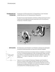
In <strong>centrifugal</strong> <strong><strong>pump</strong>s</strong> <strong>the</strong> delivery head H depends on <strong>the</strong> flow rate Q. This relationship, also<br />
called <strong>pump</strong> performance, is illustrated by <strong>curve</strong>s.<br />
During a bench test, <strong>the</strong> <strong>pump</strong> is operated at constant speed and <strong>the</strong> values Q and H are<br />
determined for <strong>the</strong> various operating points. In order to allow a comparison between <strong>the</strong><br />
various <strong>pump</strong> t ypes t hese measurement s are carried out using only wat er as liquid. Wit h<br />
<strong>the</strong>se operating points a Q/H <strong>curve</strong> be drawn connecting <strong>the</strong> points on <strong>the</strong> graph.<br />
Once <strong>the</strong> flow rate Q is defined and <strong>the</strong> delivery head H is calculated, <strong>the</strong> operating point<br />
<strong>of</strong> <strong>the</strong> plant can be determined. Usually <strong>the</strong> operating point is not on <strong>the</strong> Q/H <strong>curve</strong> <strong>of</strong> <strong>the</strong><br />
<strong>pump</strong>. Depending on <strong>the</strong> required delivery head, <strong>the</strong> <strong>centrifugal</strong> <strong>pump</strong> will find its operating<br />
point when <strong>the</strong> plant <strong>curve</strong> and <strong>pump</strong> <strong>curve</strong> meet. The flow rate rises from Q to Q .<br />
1 2
The required operating point is obtained by adapting <strong>the</strong> <strong>pump</strong> to <strong>the</strong> specified operating<br />
conditions.<br />
This can be done by <strong>the</strong> following actions:<br />
• throttling <strong>the</strong> flow<br />
• correct ing t he diamet er <strong>of</strong> t he impeller<br />
• Adjust ing t he speed <strong>of</strong> t he drive<br />
Partially closing a throttle valve or mounting an orifice plate into <strong>the</strong> discharge pipe <strong>of</strong> <strong>the</strong><br />
<strong>pump</strong> will increase <strong>the</strong> pressure drop. The plant <strong>curve</strong> is shifted.<br />
The operating point B1 (intersection point between <strong>pump</strong> <strong>curve</strong> and plant <strong>curve</strong>) moves on<br />
t he <strong>pump</strong> <strong>curve</strong> t o B2.<br />
Note: throttling reduces <strong>the</strong> overall efficiency.<br />
A throttle control or a mounted orifice plate is <strong>the</strong> less expensive control regarding <strong>the</strong><br />
investment expenses. In case <strong>of</strong> significant power requirement, an economic appraisal is<br />
highly recommended.<br />
The friction loss in an orifice plate can be calculated easily:<br />
ρ [kg/m≈]<br />
v [m/s] 1<br />
Δp [bar] v<br />
<strong>Centrifugal</strong> <strong><strong>pump</strong>s</strong><br />
Throttling <strong>the</strong> flow<br />
Orifice plate<br />
calculation
<strong>Centrifugal</strong> <strong><strong>pump</strong>s</strong><br />
Correction <strong>of</strong> <strong>the</strong><br />
impeller diameter<br />
See t he values ζ st at ed in t he t able below.<br />
Calculation:<br />
• take <strong>the</strong> figure stated in <strong>the</strong> table for d, see table ζ ,calculat e Δ p . V<br />
• if Δp varies f rom t he required value, t ake new value f or d and calculat e once more Δp .<br />
V V<br />
A correction <strong>of</strong> <strong>the</strong> impeller diameter is to be favoured when a permanent reduction <strong>of</strong><br />
flow rate or differential head is required. The performance <strong>of</strong> <strong>the</strong> <strong>pump</strong> is adjusted towards<br />
<strong>the</strong> duty point by reducing <strong>the</strong> impeller diameter.<br />
The operating point is shifted from B1 to B2. This is <strong>the</strong> point where <strong>the</strong> new <strong>pump</strong> <strong>curve</strong><br />
meet s t he plant <strong>curve</strong>.<br />
The required impeller diameter can be determined easily using following formulae:<br />
N = power consumtion<br />
D = impeller diameter<br />
Q = flow rate<br />
H = total head<br />
Note: t he ef f iciency <strong>of</strong> t he <strong>pump</strong> decreases with increasing correct ion.
A great number <strong>of</strong> various operating points can be set continuously, when modifying <strong>the</strong><br />
<strong>pump</strong> speed using a variable speed drive or frequency inverter. The operating point moves<br />
on <strong>the</strong> <strong>pump</strong> <strong>curve</strong> from B to B2.<br />
Considering <strong>the</strong> overall efficiency, this is <strong>the</strong> best way <strong>of</strong> flow control. Using a variablespeed<br />
drive or a frequency inverter additional costs can arise and should be evaluated in an<br />
economic appraisal.<br />
The f low rat e changes linearly t o t he speed.<br />
The total head changes with <strong>the</strong> square <strong>of</strong><br />
speed.<br />
The power consumption changes with <strong>the</strong><br />
third power <strong>of</strong> <strong>the</strong> speed.<br />
In <strong>the</strong> case <strong>of</strong> <strong><strong>pump</strong>s</strong> connected in parallel <strong>the</strong> fluid flows are added with corresponding<br />
delivery head. This applies to <strong><strong>pump</strong>s</strong> even with different Q/H <strong>curve</strong>.<br />
<strong>Centrifugal</strong> <strong><strong>pump</strong>s</strong><br />
Pump speed control<br />
Parallely connected<br />
<strong><strong>pump</strong>s</strong>
<strong>Centrifugal</strong> <strong><strong>pump</strong>s</strong><br />
Pumps connected in<br />
series<br />
Cavitation<br />
A multistage <strong>centrifugal</strong> <strong>pump</strong> performs as single stage <strong><strong>pump</strong>s</strong> connected in series.<br />
Note:<br />
A st at ionary <strong>pump</strong> in a syst em creat es a considerable pressure drop. Theref ore it is<br />
recommendable to install a by pass around <strong><strong>pump</strong>s</strong> which are connected in series.<br />
The overall performance <strong>curve</strong> <strong>of</strong> <strong>centrifugal</strong> <strong><strong>pump</strong>s</strong> connected in series can be calculated<br />
by adding <strong>the</strong> differential head <strong>of</strong> each <strong>pump</strong> at <strong>the</strong> relevant flow rate .<br />
Cavitation can be recognised by a strongly increased noise level <strong>of</strong> <strong>the</strong> <strong>pump</strong> with a<br />
simultaneous reduced flow rate.<br />
What causes cavitation in <strong>centrifugal</strong> <strong><strong>pump</strong>s</strong> ?<br />
The lowest pressure point in a <strong>pump</strong> occurs at <strong>the</strong> inlet <strong>of</strong> <strong>the</strong> <strong>pump</strong> impeller. Due to local<br />
pressure reduction part <strong>of</strong> <strong>the</strong> fluid may evaporate generating small vapour bubbles. These<br />
bubbles are carried along by <strong>the</strong> fluid and implode instantly when <strong>the</strong>y get into areas <strong>of</strong><br />
higher pressure. These implosions can create local pressure peaks up to 100.000 bar.<br />
If a <strong>pump</strong> is cavitating over longer periods, <strong>the</strong> impeller, <strong>the</strong> <strong>pump</strong> housing and cover will<br />
wear out. The surface is typically perforated and pitted.
How to avoid cavitation?<br />
We should ensure that at all points <strong>of</strong> <strong>the</strong> <strong>pump</strong>, <strong>the</strong> fluid pressure is higher than <strong>the</strong><br />
vapour pressure at t he corresponding t emperat ure. Take t he pressure st at ed in t he vapourpressure-<br />
table <strong>of</strong> <strong>the</strong> product to be transfered.<br />
The NPSH value <strong>of</strong> <strong>the</strong> plant must be at least 0.5 m higher than <strong>the</strong> NPSH value <strong>of</strong> <strong>the</strong><br />
<strong>pump</strong>.<br />
For a safe and cavitation free operation <strong>the</strong> following formular is valid:<br />
NPSH plant > NPSH Pump + 0.5 m<br />
The vapour pressure <strong>of</strong> <strong>the</strong> product is dependent on <strong>the</strong> temperature and will rise with<br />
increasing t emperat ure.<br />
If <strong>the</strong> product is <strong>pump</strong>ed at different temperatures <strong>the</strong> maximum vapour pressure should<br />
be used to determine <strong>the</strong> NPSH value <strong>of</strong> <strong>the</strong> plant.<br />
<strong>Centrifugal</strong> <strong><strong>pump</strong>s</strong><br />
Vapour pressure
<strong>Centrifugal</strong> <strong><strong>pump</strong>s</strong><br />
<strong>Centrifugal</strong> <strong>pump</strong><br />
types<br />
The Frist am <strong>centrifugal</strong> <strong>pump</strong> range consists <strong>of</strong> following <strong>pump</strong> types:<br />
• Frist am <strong>centrifugal</strong> <strong>pump</strong> FP<br />
The design principle <strong>of</strong> <strong>the</strong> Frist am <strong>centrifugal</strong> <strong>pump</strong> FP with open impeller and<br />
optimised volute guarantees shear sensitive handling <strong>of</strong> and minimum heat transfer to<br />
<strong>the</strong> product. Viscosities up to 1000 mPa are no problem. The fluid may contain air or gas,<br />
may be homogeneous or contain additives. Low NPSH values make it possible to use <strong>the</strong><br />
<strong>pump</strong> also under unfavourable conditions. The Frist am <strong>centrifugal</strong> <strong>pump</strong> FP is designed<br />
as a <strong>pump</strong> for flooded suction and fully suitable for CIP and SIP application.<br />
• Frist am multistage <strong>centrifugal</strong> <strong>pump</strong> FM<br />
The <strong>centrifugal</strong> <strong>pump</strong> FM is designed as a multistage <strong>pump</strong> especially developed for high<br />
delivery heads. The <strong>centrifugal</strong> <strong>pump</strong> FM can be used for difficult pressure conditions<br />
such as feed <strong>pump</strong> for filters, heat exchangers and fillers, as well as for recirculation and<br />
as booster <strong>pump</strong> in membrane filtration and reverse osmosis plants.<br />
• Frist am self-priming <strong>centrifugal</strong> <strong>pump</strong> FZ<br />
The <strong>centrifugal</strong> <strong>pump</strong> FZ works on <strong>the</strong> water ring-side channel principle. Impellers with<br />
radial blades t ransf er t he pressure energy t o t he liquid. Close clearances make it possible<br />
to obtain an excellent suction performance. Thus it is possible to <strong>pump</strong> gaseous products<br />
and to deaerate <strong>the</strong> suction line. This ensures also an optimum drain <strong>of</strong> <strong>the</strong> plant..
The selection between <strong>the</strong> <strong>pump</strong> types FP and FM also depends on <strong>the</strong> required flow rate.<br />
<strong>Centrifugal</strong> <strong><strong>pump</strong>s</strong><br />
Selection criteria
<strong>Centrifugal</strong> <strong><strong>pump</strong>s</strong><br />
<strong>Centrifugal</strong> <strong>pump</strong> FP<br />
Size selection<br />
Selecting <strong>the</strong> correct size<br />
Example:<br />
Flow rate Q = 90 m≈/h<br />
A<br />
Tot al head H = 75 m<br />
A<br />
Step 1:<br />
Select <strong>the</strong> <strong>pump</strong> size.<br />
Selected <strong>pump</strong> size: FP 3552<br />
FP sizes
Step 2:<br />
Enter <strong>the</strong> operating point <strong>of</strong> your plant into <strong>the</strong> <strong>pump</strong> diagram.<br />
If <strong>the</strong> duty point is not exactly on <strong>the</strong> <strong>pump</strong> <strong>curve</strong>, <strong>the</strong> performance <strong>of</strong> <strong>the</strong> <strong>pump</strong> can be<br />
adjusted by throttling <strong>the</strong> flow, reducing <strong>the</strong> impeller diameter or adjusting <strong>the</strong> output<br />
speed <strong>of</strong> <strong>the</strong> drive. (see page 21–23)<br />
FP 3552<br />
Impeller diameter resulting from <strong>the</strong> diagram = 230 mm<br />
<strong>Centrifugal</strong> <strong><strong>pump</strong>s</strong><br />
<strong>Centrifugal</strong> <strong>pump</strong> FP<br />
performance diagram
<strong>Centrifugal</strong> <strong><strong>pump</strong>s</strong><br />
Power consumption<br />
<strong>of</strong> <strong>the</strong> <strong>pump</strong><br />
<strong>pump</strong> efficiency<br />
Step 3:<br />
Find t he power consumpt ion <strong>of</strong> t he <strong>pump</strong> at t he point in t he diagram where t he power<br />
<strong>curve</strong> <strong>of</strong> t he impeller used meet s t he design f low rat e.<br />
Select <strong>the</strong> motor with <strong>the</strong> next higher power rating.<br />
Power consumption according to <strong>the</strong> diagram: N = 26 kW<br />
selected motor: 30.0 kW<br />
Step 4:<br />
Check t he ef f iciency<br />
η<br />
= Q H<br />
η =<br />
× × ρ<br />
367 × N<br />
90 × 75 × 1<br />
367 × 26<br />
Q [m≈/h]<br />
H [m]<br />
N [kW]<br />
ρ [kg/dm≈]<br />
ρ water = 1 kg/dm≈
Step 5:<br />
Check if NPSH plant > NPSH Pump<br />
Resulting NPSH value <strong>of</strong> <strong>the</strong> <strong>pump</strong> from <strong>the</strong> diagram = 2.4 m<br />
<strong>Centrifugal</strong> <strong><strong>pump</strong>s</strong><br />
Check NPSH value
<strong>Centrifugal</strong> <strong><strong>pump</strong>s</strong><br />
Self- priming<br />
<strong>centrifugal</strong> <strong>pump</strong> FZ<br />
Size selection<br />
Selecting <strong>the</strong> correct size<br />
Example:<br />
Flow rate Q = 30 m≈/h<br />
A<br />
Tot al head H = 24 m<br />
A<br />
Step 1:<br />
select <strong>the</strong> <strong>pump</strong> size whose <strong>curve</strong> is above to <strong>the</strong> operating point <strong>of</strong> <strong>the</strong> plant.<br />
Selected <strong>pump</strong> size: FZ 22<br />
FZ sizes
Note:<br />
The performance <strong>of</strong> FZ <strong><strong>pump</strong>s</strong> can be adjusted to <strong>the</strong> required operating point only by<br />
t hrot t ling t he f low (see page 21/22) or variat ion <strong>of</strong> t he speed (see page 23). It is not<br />
possible to modify <strong>the</strong> impeller diameter.<br />
<strong>Centrifugal</strong> <strong><strong>pump</strong>s</strong><br />
Power consumption<br />
<strong>of</strong> <strong>the</strong> <strong>pump</strong>
<strong>Centrifugal</strong> <strong><strong>pump</strong>s</strong><br />
Multistage<br />
<strong>centrifugal</strong> <strong>pump</strong> FM<br />
Step 2:<br />
Find t he power consumpt ion <strong>of</strong> t he <strong>pump</strong> at t he point in t he diagramm where t he power<br />
<strong>curve</strong> meets <strong>the</strong> design flow rate. Select <strong>the</strong> motor with <strong>the</strong> next higher power rating.<br />
From <strong>the</strong> diagram: N = 6.7 kW, selected motor: 7.5 kW<br />
The selection is carried out <strong>the</strong> same way as single-stage <strong>centrifugal</strong> <strong><strong>pump</strong>s</strong> FP are selected<br />
(See page 28).


![Förderhöhe [m] - Fristam Pumpen F. Stamp KG](https://img.yumpu.com/2915008/1/190x245/forderhohe-m-fristam-pumpen-f-stamp-kg.jpg?quality=85)