Download Manual - Ritron
Download Manual - Ritron
Download Manual - Ritron

You also want an ePaper? Increase the reach of your titles
YUMPU automatically turns print PDFs into web optimized ePapers that Google loves.
®<br />
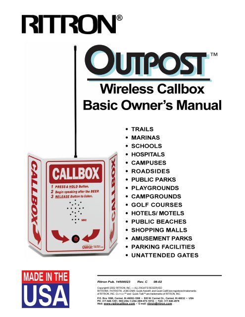
Wireless Callbox<br />
Basic Owner’s <strong>Manual</strong><br />
(PRELIMINARY)<br />
• TRAILS<br />
• MARINAS<br />
• SCHOOLS<br />
• HOSPITALS<br />
• CAMPUSES<br />
• ROADSIDES<br />
• PUBLIC PARKS<br />
• PLAYGROUNDS<br />
• CAMPGROUNDS<br />
• GOLF COURSES<br />
• HOTELS/ MOTELS<br />
• PUBLIC BEACHES<br />
• SHOPPING MALLS<br />
• AMUSEMENT PARKS<br />
• PARKING FACILITIES<br />
• UNATTENDED GATES<br />
<strong>Ritron</strong> Pub 14500023 Rev C 08-02<br />
Copyright© 2002 RITRON, INC — ALL RIGHTS RESERVED<br />
RITRON®, PATRIOT®, JOBCOM®, Quick Assist®, and Quiet Call® are registered trademarks<br />
of RITRON, INC OUTPOST TM and Quick Talk TM are trademarks of RITRON, INC<br />
PO Box 1998, Carmel, IN 46082-1998 • 505 W Carmel Dr, Carmel, IN 46032 • USA<br />
PH: 317-846-1201; 800-USA-1-USA (800-872-1872) • FAX: 317-846-4978<br />
Web: wwwradiocallboxcom • E-mail: ritron@ritroncom
QUICK TALK<br />
From om <strong>Ritron</strong><br />
on<br />
1-800-USA-1USA<br />
RECHARG EABLE<br />
This manual (<strong>Ritron</strong> Item: RQX-150/450/446/454),<br />
covers programming, operation and installation of<br />
the OUTPOST 2–Way Callbox<br />
NOTICE: The Outpost is not intended for communicating<br />
information to protect life or property, and must<br />
not be used for these purposes<br />
To reduce the risk of fire, electric shock or personal injury,<br />
follow these basic safety instructions when using this unit:<br />
1<br />
2<br />
3<br />
ACCESSORIES<br />
These replacement and optional items are available from<br />
<strong>Ritron</strong> and its authorized dealers<br />
Item<br />
WHAT THIS MANUAL COVERS<br />
AFB-1545<br />
EXPO-12<br />
RAM-1545<br />
Description<br />
Standard 16 in Flexible Whip Antenna<br />
External Power 12VDC Input/<br />
Battery Back-Up Kit<br />
Magnetic-Mount Antenna w/ 20 ft of Cable<br />
and a BNC Connector<br />
14280012 Standard Instruction Nameplate??? Optional<br />
Tamper-Resistant Enclosure<br />
EXPO-12<br />
EXTERNAL<br />
POWER/ BATTERY<br />
BACK-UP KIT<br />
l<br />
l<br />
l<br />
+ + +<br />
+ + +<br />
DIMENSIONS<br />
RAM-1545<br />
ANTENNA<br />
The OUTPOST dimensions, including the Battery Housing and<br />
Antenna Connector are: 7 11 /16" H x5" W x4" D<br />
The OUTPOST dimensions, including EXPO-12, Strain Relief<br />
and Antenna Connector are: 8 7 /16" H x5" W x4" D<br />
The OUTPOST Placard dimensions are shown below:<br />
CALLBOX<br />
CALLBOX<br />
1 PRESS & HOLD Button.<br />
2 Begin speaking after the BEEP.<br />
3 RELEASE Button to listen.<br />
MIC<br />
OUTPOST<br />
CALLBOX<br />
10"<br />
CALLBOX<br />
7"<br />
10 1 /4" 4 1 /16"<br />
— — — WARNING — — —<br />
IMPORTANT SAFETY INFORMATION<br />
Read and follow all instructions<br />
Use only alkaline D-cell batteries<br />
During thunderstorms, avoid contact with this unit and any<br />
external antenna system or wiring<br />
DESCRIPTION<br />
TABLE OF CONTENTS<br />
PAGE<br />
WHAT THIS MANUAL COVERS ii<br />
ACCESSORIES ii<br />
DIMENSIONS ii<br />
WARNINGS ii<br />
ABOUT THE OUTPOST WIRELESS CALLBOX 1<br />
General Information 1<br />
OUTPOST Models and Frequencies 1<br />
Model Identification 1<br />
OPERATION NOTES 2<br />
INTERCOM (ALWAYS ON) FEATURE 2<br />
OPERATING THE OUTPOST 2<br />
To Initiate a Call 2<br />
To Receive a Response 2<br />
IDENTIFICATION OF<br />
CONTROLS & CONNECTORS 3<br />
INSTALLING BATTERIES<br />
INTO THE OUTPOST 4<br />
BATTERY LIFE 4<br />
PROGRAMMING THE OUTPOST<br />
(RQX-150/450 ONLY) 5<br />
To Place the OUTPOST<br />
into Programming Mode 5<br />
To Program a Frequency and QC Tone 5<br />
PC PROGRAMMING THE OUTPOST<br />
(RQX-150/450/454) 6<br />
OPERATION NOTES 5<br />
INSTALLING THE OUTPOST 7<br />
To Mount the OUTPOST 7<br />
Coverage 7<br />
EXPO–12 EXTERNAL POWER 12 VDC INPUT/<br />
BATTERY BACKUP KIT (OPTIONAL) 8<br />
Back-Up Battery Installation 8<br />
SEALING THE ANTENNA 9<br />
Applying seal tape 9<br />
DEALER NOTES (BLANK) PAGE 10<br />
FCC LICENSING AND REGULATIONS 11<br />
RITRON LIMITED WARRANTY 11<br />
COMPATIBLE PRODUCTS 12<br />
CARE AND MAINTENANCE 14<br />
Moisture 14<br />
Temperature 14<br />
Vibrations/ Shock 14<br />
Chemicals 14<br />
FIGURES<br />
DESCRIPTION<br />
PAGE<br />
1: OUTPOST FRONT HOUSING<br />
CONTROLS & CONNECTORS 3<br />
2: BACK HALF OF HOUSING,<br />
SHOWING CELL POLARITY 4<br />
3: INSTALLING THE OUTPOST 7<br />
4: INTERNAL VIEW OF EXPO–12 8<br />
TABLES<br />
DESCRIPTION<br />
PAGE<br />
1: FREQUENCY CODES 5<br />
2: QUIET CALL TONE CODES 6<br />
Page ii
®<br />
OutPost Basic Owner’s <strong>Manual</strong><br />
ABOUT THE OUTPOST WIRELESS CALLBOX<br />
General Information<br />
The OUTPOST Callbox is a 2-way radio transceiver<br />
for communicating with portable, mobile and stationary<br />
radios, or through radio repeaters<br />
The OUTPOST can be easily programmed to operate<br />
on either an existing or a new radio frequency with or<br />
without Quiet Call (CTCSS sub-audible coded<br />
squelch) This enables all your radio-equipped personnel<br />
to respond immediately to transmissions from the<br />
OUTPOST Callbox<br />
The OUTPOST is housed in a weather–resistant<br />
enclosure, so it can be installed in a wide variety of<br />
indoor or outdoor locations Because its six D-cell<br />
Alkaline batteries power the unit for about one year<br />
(depending on temperatures and amount of use), the<br />
OUTPOST does not require AC line power<br />
An optional External Power 12VDC Input/ Battery<br />
Backup Kit (EXPO-12) is available See Page 8<br />
OUTPOST Models and Frequencies<br />
Four OUTPOST models are available, as indicated<br />
below: one for VHF Conventional radio systems, one<br />
for UHF Conventional radio systems, and two for UHF<br />
Conventional or Trunking radio systems<br />
DO NOT drill or penetrate the internal RF electronics<br />
enclosure with any additional holes Use only the<br />
pre-drilled mounting holes<br />
Model Identification<br />
Model Band Frequency Range Signalling Formats<br />
RQX-150* VHF-FM 150–155 MHz Std, 155–160 MHz Opt CTCSS<br />
RQX-450* UHF-FM 460–470 MHz Std, 450–460 MHz Opt CTCSS<br />
RQX-446*** UHF-FM 460-470 MHz, Wide or Narrow Band TX,<br />
460 MHz Opt CTCSS/ DCS (1stQ 2002)<br />
RQX-454** UHF-FM 450–470 MHz, Wide or Narrow Band TX CTCSS/ DCS/<br />
DTMF ANI/LTR, Passport<br />
RQX-454-NP** UHF-FM 450–470 MHz Narrowband CTCSS/ DCS/<br />
DTMF ANI/LTR, Passport<br />
* The RQX–150/ –450 models are PTT-programmable to specific tones and channel frequencies They are also<br />
PC-programmable to any frequency channel within the radio's band, using the RPT–PCPK–30R20 or higher PC Software<br />
** The RQX–454 model is PC-programmable ONLY and requires the RPT–PCPK–81R12 or higher PC Software<br />
*** The RQX-446 is PTT-programmable and/or PC-programmable Software is not available at time of printing Call <strong>Ritron</strong><br />
for details<br />
The OUTPOST model number appears on a label on the front bottom half<br />
of the RF enclosure<br />
<strong>Ritron</strong> designs, manufactures, and supplies reliable, professional wireless<br />
communication products for users worldwide <strong>Ritron</strong> wireless products will<br />
improve the operation, safety, and profitability of any organization <strong>Ritron</strong><br />
offers a full line of mobile, portable, and base station two-way radios and<br />
repeaters for use with the OUTPOST Callbox Refer to pages 12 and 13<br />
Refer to page 5 for instructions on matching the OUTPOST operating<br />
frequency to that of an existing two-way radio system<br />
For assistance, call RITRON at 800-872-1872, or go to wwwritroncom<br />
Page 1
®<br />
OutPost Basic Owner’s <strong>Manual</strong><br />
OPERATING THE OUTPOST CALLBOX<br />
NOTE: The OUTPOST will not receive a call until a<br />
call has been initiated by the OUTPOST<br />
THE OUTPOST AUTOMATICALLY SHUTS<br />
OFF WHENEVER THERE IS INACTIVITY<br />
FOR TEN (10) SECONDS<br />
To Initiate a Call:<br />
Press and hold the ON/PTT Button on the unit, listen<br />
for the “beep,” and begin speaking into the MIC For<br />
best communication, speak as closely as possible into<br />
the microphone The OUTPOST is designed so you<br />
will be heard clearly when you speak, while pressing<br />
the ON/PTT Button, at a distance of up to 3 feet from<br />
the microphone<br />
To Receive a Response:<br />
1 When you have finished speaking, release the<br />
ON/PTT Button<br />
2<br />
Any reply to you will be heard through the<br />
OUTPOST speaker If a reply is not received<br />
within 10 seconds of releasing the ON/PTT<br />
Button, the unit sounds a low double tone and<br />
shuts off automatically<br />
To call again, press and hold the ON/ PTT Button<br />
and begin speaking after the “beep”<br />
OPERATION NOTES<br />
• The OUTPOST must be powered with Alkaline batteries ONLY—or alternately,<br />
with the optional External Power 12VDC Input/ Battery Backup Kit (EXPO–12)<br />
• If there has been no activity for 10 seconds—ie, either the ON/PTT Button<br />
has not been pressed/ released within 10 seconds, or no reply has been<br />
heard within 10 seconds—the unit automatically shuts OFF The automatic<br />
shut-off feature is designed to increase battery life<br />
INTERCOM (Always-On) FEATURE FOR THE RQX-454/454-N<br />
The RQX-454/454-N can be programmed to<br />
operate as a two-way intercom When this feature<br />
is activated the automatic shut-off is disabled and<br />
the callbox will remain on in “standby” mode<br />
allowing it to receive a call from another radio at<br />
any time Since the radio is under constant<br />
current drain “always on in the standby mode”, it<br />
would make the use of batteries impractical<br />
When using this feature, it is recommended that<br />
the optional EXPO-12 external power kit be used<br />
To Enable the Intercom Feature: The Intercom<br />
Mode can only be enabled using the PC<br />
1<br />
2<br />
Programmer (PC Programming Software<br />
RPT-PCPK-80R12)<br />
Refer to the PC PROGRAMMING THE<br />
OUTPOST section to program the<br />
RQX-454/454-N<br />
Once the radios’ information has been “Read”,<br />
select EDIT, select TUNE RADIO, select<br />
MISC, select Power Saver, select TUNE, set<br />
“PowerSaver Off Time” to “0” (zero), select<br />
SAVE, select EXIT, and then remove power<br />
from the radio and disconnect the program<br />
ming cable The RQX-454/454-N is now set<br />
for Intercom Mode<br />
Page 2
Refer to FIG–1<br />
®<br />
OutPost Basic Owner’s <strong>Manual</strong><br />
IDENTIFICATION OF CONTROLS AND CONNECTIONS<br />
1 ANTENNA CONNECTOR<br />
The antenna radiates radio signals Before using<br />
the OUTPOST, make sure the antenna is securely<br />
fastened into the connector If the OUTPOST is to<br />
be used outdoors, see page 6 for instructions<br />
on properly sealing the antenna connector<br />
2 PROGRAM BUTTON (RQX-150/450/446)<br />
This button is used to enter frequency and Quiet<br />
Call code information<br />
3 OFF BUTTON (RQX-150/450/446)<br />
This button is used to turn the OUTPOST OFF<br />
when programming is complete<br />
4 PROGRAM SAVE BUTTON (RQX-150/450/446)<br />
This button is used to save the programmed<br />
information<br />
5 PROGRAM ENABLE BUTTON (RQX-150/450/446)<br />
Pressing this button when the unit is ON puts the<br />
OUTPOST into Programming Mode<br />
NOTE: Model RQX-454 must be programmed by<br />
a RITRON Dealer<br />
6 SPEAKER<br />
After a message has been sent from the OUTPOST,<br />
any reply from another radio may be heard through<br />
the speaker<br />
7 MICROPHONE ("MIC")<br />
For best communication, speak as closely as<br />
possible into the microphone The OUTPOST is<br />
designed so you will be heard clearly when you<br />
speak, while pressing the ON/PTT Button, at a<br />
distance of up to 3 feet from the microphone<br />
8 ON/ PTT BUTTON<br />
The OUTPOST is OFF until the user turns it ON<br />
by pressing and holding the ON/PTT Button The<br />
unit sounds an audible “beep” to confirm it is ready<br />
for a message; when the user is finished speaking,<br />
he releases the button to wait for a reply If<br />
there is no reply within 10 seconds, the unit<br />
sounds an audible “beep” and automatically shuts<br />
OFF<br />
9 IN-LINE BATTERY CONNECTOR<br />
The in-line battery connector connects the radio to<br />
the Battery<br />
10 MOUNTING HOLES<br />
Mounting holes accommodate #6 panhead screws<br />
to securely mount the unit to a variety of surfaces<br />
11 BATTERY HOLDER<br />
The rugged battery holder securely holds six (6)<br />
D-cell batteries in place<br />
1 ANTENNA CONNECTOR<br />
2 PROGRAM BUTTON<br />
3 OFF BUTTON<br />
4 SAVE BUTTON<br />
5 ENABLE BUTTON<br />
MUSHROOM-HEAD FASTENER STRIP (3)<br />
6 SPEAKER<br />
7 MICROPHONE<br />
8 ON/PTT BUTTON<br />
9 IN-LINE BATTERY CONNECTOR<br />
(Front View of Top Half)<br />
CAPTIVE SCREWS (4)<br />
(CONNECTED TO ON/ PTT BUTTON)<br />
(CONNECTED TO RADIO BOARD)<br />
(SEE PAGE 3 FOR ITEMS 10 AND 11)<br />
(Internal View of Top Half)<br />
FIG–1: OUTPOST FRONT HOUSING CONTROLS & CONNECTORS<br />
For assistance, call RITRON at 800-872-1872, or go to wwwritroncom<br />
Page 3
®<br />
OutPost Basic Owner’s <strong>Manual</strong><br />
Refer to FIG–2<br />
INSTALLING BATTERIES INTO THE OUTPOST<br />
1<br />
2<br />
Loosen the four (4) plastic screws at the corners<br />
of the front half of the housing These screws are<br />
captive to the housing; to prevent damaging them,<br />
DO NOT remove them<br />
Disconnect the in-line connector between the<br />
Front and the back halves of the enclosure<br />
3 Note the positive and negative polarities ("+" and "–")<br />
of each cell Press six Alkaline D-cells into proper<br />
position<br />
NOTE: When all batteries are in place, confirm<br />
that the RED wire contacts the positive (+)<br />
pole of the first battery, and the BLACK<br />
wire contacts the negative (–) pole of the<br />
last battery, as shown in FIG–2<br />
4 Reconnect the in-line connector between the Front<br />
and the back halves of the RF enclosure<br />
DO NOT pinch gasket, overtighten, cross-thread, strip, or remove captive<br />
screws Failure to heed this warning will prevent proper sealing of the RF<br />
enclosure and will result in voiding Manufacturers Warranty<br />
10 PRE-DRILLED<br />
MOUNTING HOLES<br />
(4 CORNERS)<br />
RED WIRE (+)<br />
! ! WARNING ! !<br />
DO NOT USE NICKEL METAL<br />
HYDRIDE BATTERIES IN THE<br />
OUTPOST<br />
BLACK WIRE (–)<br />
11 BATTERY HOLDER<br />
IN-LINE CONNECTOR<br />
(INSIDE VIEW)<br />
FIG–2: BACK HALF OF HOUSING, SHOWING CELL POLARITY<br />
BATTERY LIFE<br />
• Use non-rechargeable Alkaline D-cell batteries for maximum battery life<br />
• The OUTPOST should operate for one (1) year on a set of Alkaline batteries,<br />
depending upon usage<br />
• Cooler temperatures degrade battery life Exposure to 10° C (50° F) will reduce<br />
battery life to 90% of normal Exposure to –20° C (–4° F) will reduce battery<br />
life to 35% of normal<br />
Page 4
NOTES: Refer to Table 1 (Frequency Codes) and Table 2<br />
(QC Tone Codes) when programming the OUTPOST<br />
For PROGRAMMING BUTTON locations, refer to the Internal<br />
View of the Front of the RF housing in FIG–1, page 3<br />
To place the OUTPOST into Programming Mode:<br />
1 Loosen the (4) captive screws in the corners of the unit These<br />
screws are captive to the housing; to prevent damaging them,<br />
DO NOT remove the screws from the RF housing<br />
2 Make sure the unit has batteries installed<br />
NOTE: The voltage of the batteries must be greater than<br />
6 VDC to program properly<br />
3 Press and release the ON/PTT Button on the front of the unit<br />
4 Press and release the PROGRAM ENABLE BUTTON An audible “beep”<br />
will sound to confirm the unit is in programming mode<br />
To read out (beep out) Radio Channel content:<br />
5 Press and release the Program Save Button The radio will begin<br />
to sound a series of beeps; each series of beeps is equal to one<br />
digit of each 2-digit frequency code or Quiet Call Code (see chart<br />
below) that is programmed into the radio See Tables 1 and 2 on<br />
this page<br />
6 After the beeps are completed, a triple tone will sound<br />
To Program Frequency and QC Tone Codes:<br />
7 Choose a frequency code (Table 1) and, if desired, a QC tone<br />
code (Table 2) If you are not using a QC tone, program “44”<br />
(No Tone) for the QC code<br />
8 Enter the codes in the sequence shown below by clicking the<br />
PROGRAM BUTTON the number of times equal to each digit of the<br />
codes<br />
EXAMPLE: Frequency Code 02, Tone Code 44<br />
• Click the PROGRAM BUTTON ten times to program “0”, pause;<br />
the unit sounds a “beep”<br />
• Click the PROGRAM BUTTON two times to program “2”, pause;<br />
the unit sounds a “beep”<br />
• Click the PROGRAM BUTTON four times to program “4”, pause;<br />
the unit sounds a “beep”<br />
• Click the PROGRAM BUTTON four times to program “4”, pause;<br />
the unit sounds a “beep”<br />
®<br />
OutPost Basic Owner’s <strong>Manual</strong><br />
HOW TO PTT PROGRAM THE OUTPOST ( MODELS RQX-150/450/446 ONLY )<br />
release the PROGRAM OFF BUTTON to turn the unit Off, and<br />
start over<br />
• If the unit does not sound the confirming triple tone when<br />
you attempt to save your programming, the unit was<br />
factory- or dealer-customized to disable programming<br />
Consult the radio owner, or your Dealer<br />
• Refer to Frequency and Tone Code tables at right and on<br />
the following page<br />
TABLE 1: FREQUENCY CODES<br />
(VHF Business Band)<br />
01 154600 Green Dot<br />
02 154570 Blue Dot<br />
03 151625 Red Dot<br />
04 151955 Purple Dot<br />
05 151925<br />
06 154540<br />
07 154515<br />
08 154655<br />
09 151685<br />
10 151715<br />
11 151775<br />
12 151805<br />
13 151835<br />
14 151895<br />
15 154490<br />
16 151655<br />
17 151745<br />
18 151865<br />
VHF Business Band<br />
Model RQX-150<br />
MHz<br />
(UHF Business Band)<br />
QUICK<br />
TALK<br />
FREQ CODE<br />
Frequency Color<br />
UHF Business Band<br />
Model RQX-450<br />
MHz<br />
Frequency Color<br />
FREQUENCY CODE "02" TONE CODE "44"<br />
1 st (pause)<br />
2 nd (pause)<br />
1 st (pause)<br />
2 nd (pause)<br />
digit digit digit digit<br />
“0” (pause) “2” (pause) “4” (pause) “4” (pause)<br />
9 When all four digits are programmed, press and release the<br />
PROGRAM SAVE Button The unit sounds a triple tone<br />
NOTE: An error tone sounds if you try to save an incorrect<br />
digit To correct the programming, press and release the<br />
PROGRAM OFF BUTTON When the unit sounds a low tone,<br />
you may start over at Step #3<br />
10 Press and release the PROGRAM OFF BUTTON; the unit sounds a low<br />
tone The OUTPOST is now ready for use<br />
NOTES: • Ten (10) clicks = 0 (zero)<br />
• Program “44” to enter “No Tone” for Quiet Call You must<br />
enter “44” to match radios without tone codes<br />
• If you make a programming click error, press and<br />
01 4677625 J<br />
02 4678125 K<br />
03 4645500 Yellow Dot<br />
04 4645000 Brown Dot<br />
05 4678500 Silver Star<br />
06 4678750 Gold Star<br />
07 4679000 Red Star<br />
08 4679250 Blue Star<br />
09 4692625<br />
10 4625750 White Dot<br />
11 4626250 Black Dot<br />
12 4626750 Orange Dot<br />
13 4643250<br />
14 4648250<br />
15 4695000<br />
16 4695500<br />
17 4632625<br />
18 4649125<br />
19 4646000<br />
20 4647000<br />
For assistance, call RITRON at 800-872-1872, or go to wwwritroncom<br />
Page 5
®<br />
OutPost Basic Owner’s <strong>Manual</strong><br />
TABLE 2: QUIET CALL TONE CODES<br />
QUICK<br />
TALK<br />
QC<br />
CODE<br />
01<br />
02<br />
03<br />
04<br />
05<br />
06<br />
07<br />
08<br />
09<br />
10<br />
11<br />
12<br />
13<br />
14<br />
15<br />
16<br />
17<br />
18<br />
19<br />
20<br />
21<br />
22<br />
23<br />
24<br />
25<br />
26<br />
Freq<br />
( Hz )<br />
670<br />
719<br />
744<br />
770<br />
797<br />
825<br />
854<br />
885<br />
915<br />
948<br />
974<br />
1000<br />
1035<br />
1072<br />
1109<br />
1148<br />
1188<br />
1230<br />
1273<br />
1318<br />
1365<br />
1413<br />
1462<br />
1514<br />
1567<br />
1622<br />
Other<br />
Radio Brands<br />
Tone<br />
Code<br />
XZ<br />
XA<br />
WA<br />
XB<br />
SP<br />
YZ<br />
YA<br />
YB<br />
ZZ<br />
ZA<br />
ZB<br />
1Z<br />
1A<br />
1B<br />
2Z<br />
2A<br />
2B<br />
3Z<br />
3A<br />
3B<br />
4Z<br />
4A<br />
4B<br />
5Z<br />
5A<br />
5B<br />
QUICK<br />
TALK<br />
QC<br />
CODE<br />
27<br />
28<br />
29<br />
30<br />
31<br />
32<br />
33<br />
34<br />
35<br />
36<br />
37<br />
38<br />
39<br />
40<br />
41<br />
42<br />
43<br />
*44<br />
45<br />
46<br />
47<br />
48<br />
49<br />
50<br />
51<br />
Freq<br />
( Hz )<br />
1679<br />
1738<br />
1799<br />
1862<br />
1928<br />
2035<br />
2107<br />
2181<br />
2257<br />
2336<br />
2418<br />
2503<br />
694<br />
1598<br />
1655<br />
1713<br />
1773<br />
NoTone<br />
1835<br />
1899<br />
1966<br />
1995<br />
2065<br />
2291<br />
2541<br />
Other<br />
Radio Brands<br />
Tone<br />
Code<br />
6Z<br />
6A<br />
6B<br />
7Z<br />
7A<br />
M1<br />
--<br />
--<br />
--<br />
--<br />
--<br />
--<br />
--<br />
--<br />
--<br />
--<br />
--<br />
--<br />
--<br />
--<br />
--<br />
--<br />
--<br />
--<br />
--<br />
* Use Code "44" to program No Tone for systems without a<br />
Coded Squelch Interference Eliminator feature Refer to<br />
Page 4, Step 5 and NOTES at the bottom of the page<br />
1<br />
2<br />
3<br />
4<br />
5<br />
6<br />
7<br />
Loosen the (4) captive screws in the corners of<br />
the RF enclosure These screws are captive to<br />
the housing; to prevent damaging them, Do Not<br />
remove the screws from the housing<br />
Lift the top half of the RF enclosure from the<br />
bottom<br />
Remove the (4) metal seal screws from the front<br />
of the top half of the RF enclosure<br />
Carefully lift the radio assembly away from the<br />
inside of the front of the RF enclosure and plug<br />
the Programming Cable adaptor into the 35mm<br />
Jack located on the top of the radio assembly<br />
Execute the Programming Software for the radio<br />
on your computer<br />
Make sure the radio has batteries installed or is<br />
powered by an external 12 VDC source through<br />
the EXPO-12 To turn the unit on, press the ON/<br />
PTTbutton on the front of the unit<br />
Follow the instructions for PC programming the<br />
radio according to the software<br />
When PC Programming:<br />
the VHF RQX-150 will read out as a model SST-150<br />
the UHF RQX-450 will read out as a model SST-450<br />
the UHF RQX-446 will read out as a model RQX-446<br />
the UHF RQX-454-N will read out as a model SST-454<br />
WARNING: ONLY FREQUENCY AND TONE<br />
INFORMATION should be altered when using the<br />
RITRON Programming Software!!! Changes to<br />
other features could render the unit inoperable<br />
PC PROGRAMMING THE OUTPOST<br />
(RQX-150/450/446/454)<br />
If your frequency is not found in Table 1, page 5,<br />
the frequency and tone must be programmed with<br />
a PC using specialized RITRON Programming<br />
Software<br />
NOTES: Only RITRON dealers have access to<br />
programming software Contact RITRON at<br />
800-USA-1-USA for the location of your nearest<br />
Authorized RITRON Dealer<br />
• Models RQX–150/450 require<br />
RPT–PCPK–30 R19 PC for PC<br />
programming<br />
• Models RQX–454/454–NP require<br />
RPT–PCPK–80R12 for PC<br />
programming<br />
• Model RQX–446 requires PC software<br />
not available at time of printing Please<br />
contact RITRON for furhter details<br />
8 After the programming is complete and the<br />
information has been saved to the radio, unplug<br />
the radio from the battery holder or the EXPO-<br />
12 and remove the Programming Cable<br />
Adaptor<br />
9 Plug the battery cable or the EXPO-12 Power<br />
Connector back into the radio<br />
10 Carefully place the radio assembly into the front<br />
case and secure it with the (4) metal seal<br />
screws<br />
11 Secure the top of the RF enclosure to the<br />
bottom of the Callbox with the (4) captive<br />
screws<br />
NOTE: The antenna may be positioned to<br />
ei therside of the RF enclosure<br />
FACTORY DEFAULT<br />
l Unit is set for medium volume<br />
l Battery saver "Auto Shut-off" is set<br />
for 10 seconds<br />
Page 6
®<br />
OutPost Basic Owner’s <strong>Manual</strong><br />
RQX PROGRAMMING INSTRUCTIONS<br />
Reprogramming the Automatic Shut-off Time<br />
RQX-150/450 Standard and XT Models: Use PC Programming Software RPT-PCPK-30R19<br />
1 Refer to the Owner’s <strong>Manual</strong> for disassembly instructions to PC Program the radio<br />
2 Execute the Programming Software and go to the Main Menu page<br />
3 Plug the programming cable into the RQX and power the RQX by pressing the button on the front case<br />
4 Press “1” to read the RQX information<br />
5 The RQX-150/-XT will read out as a Model SST-150<br />
The RQX-450/-XT will read out as a Model SST-450<br />
6 Use the “down arrow” key or “enter” key to get to the “Access Radio Tech Fields” field<br />
7 Type “tune!”<br />
8 The cursor should automatically go to the “Battery Saver Off time” field<br />
9 The factory default time is 10 seconds Type in the time(in seconds from 1 to 256) for your desired shut-off<br />
time<br />
NOTE: DO NOT type “0” for the “Battery Saver Off Time” unless your RQX has a label marked “314G0158”<br />
on the outside of the case Doing so will render the RQX inoperable Units that do not have the 314G0158<br />
label do not contain the necessary firmware for the “On all the time “ option<br />
10 Press the “F10” key<br />
11 Press ”2”<br />
12 Wait for the next prompt, press “C”<br />
13 Wait for the “radio programmed ok” message<br />
12 Remove the power from the RQX and unplug the RQX from the computer<br />
RQX-454 Standard and XT Model: Use PC Programming Software RPT-PCPK-80R12<br />
1 Refer to the Owner’s <strong>Manual</strong> for disassembly instructions to PC Program the radio<br />
2 Execute the Programming Software and go to the Main Title Page<br />
3 Click on “Plus-Series”, then click on “Start”<br />
4 Plug the programming cable into the RQX and power the RQX by pressing the button on the front case<br />
5 Click on “Radio”, then click on “Read Radio”<br />
6 The RQX-454 will read out as a Model RQX-454<br />
7 Click on “Edit”, then click on “Tune Radio”<br />
8 Click on “Misc”<br />
9 Click on “Power Saver Off Time”, then click on “Tune”<br />
10 To calculate the decimal number for your desired off time, divide your desired time (in seconds) by 32<br />
Round the number to two places pass the decimal point<br />
Example: 10 seconds(factory default) divided by 32 = 31<br />
NOTE: 1 The maximum amount of shut-off times is 255 seconds<br />
2 DO NOT type “0” for the “Battery Saver Off Time” unless your RQX-454 has firmware<br />
version 114 or later Doing so will render the RQX inoperable Units that do not have<br />
version 114 or later do not contain the necessary firmware for the “On all the time “<br />
option To check, click on “Edit”, then click on “Radio ID”<br />
11 Type in your decimal number<br />
12 Click on “Save”<br />
13 Click on “Exit”<br />
14 Remove the power from the RQX and disconnect the RQX from the computer<br />
For assistance, call RITRON at 800-872-1872, or go to wwwritroncom<br />
Page 7
®<br />
OutPost Basic Owner’s <strong>Manual</strong><br />
The OUTPOST can be mounted to virtually any surface<br />
with four (4) #6 panhead screws Choose a type of<br />
screw thread and screw length which will hold firmly<br />
in the surface to which the unit will be mounted<br />
To Mount the OUTPOST<br />
(Refer to FIG–3)<br />
1<br />
Remove the Front half of the RF housing by<br />
loosening the four (4) plastic screws captive to the<br />
RF housing To prevent loss or damage, DO NOT<br />
remove these screws<br />
2 Disconnect the in-line connector between Front<br />
and the Back halves of the RF housing<br />
3 Insert a #6 panhead screw into each of four (4)<br />
corner holes in the Back half of the RF housing<br />
Position the RF housing in the chosen location<br />
and secure it in place with the screws<br />
4 Connect the in-line connector between the Front<br />
and the Back halves of the RF housing<br />
5 Fasten the Front half to the Back half of the RF<br />
housing with the four (4) captive screws<br />
LOCATIONS FOR<br />
PRE-DRILLED MOUNTING<br />
HOLES USE #6<br />
PANHEAD SCREWS<br />
INSTALLING THE OUTPOST<br />
D<br />
6<br />
7<br />
8<br />
DO NOT drill or penetrate the internal<br />
RF electronics enclosure with any<br />
additional holes Use only pre-drilled<br />
mounting holes<br />
Insert, rotate and lock the antenna into the<br />
antenna jack Orient the antenna vertically<br />
If the OUTPOST is to be used outdoors, it is<br />
imperative that the antenna connector be<br />
sealed with seal tape Use Grainger #2A-459,<br />
Radio Shack #278-1647, or equivalent Refer to<br />
instructions on the seal tape package<br />
To install the Message Placard, align the center<br />
of its hole over the ON/PTT pushbutton, and the<br />
mushroom-head fastener strips on the back of the<br />
placard panel with the strips on the front of the<br />
OUTPOST Press firmly to interlock the strips,<br />
snapping the panel into position<br />
Coverage<br />
Depending on unit location and installation height<br />
of a standard antenna, the OUTPOST covers the<br />
area of a 1-Watt portable radio of the same<br />
frequency band To increase range, use an<br />
external antenna that is mounted higher See the<br />
RAM–1545 Magnet Mount Antenna on page ii<br />
CAPTIVE<br />
SCREW<br />
LOCATION FOR PRE-<br />
DRILLED MOUNTING<br />
HOLES USE #6 PANHEAD<br />
SCREW<br />
LOCATION FOR PRE-<br />
DRILLED MOUNTING<br />
HOLES USE #6 PANHEAD<br />
SCREW<br />
POLARIZED IN-LINE<br />
BATTERY CONNECTOR<br />
(3) MUSHROOM-HEAD<br />
FASTENER STRIPS<br />
(View of Battery Holder)<br />
(Front View of the OUTPOST)<br />
FIG–3: INSTALLING THE OUTPOST<br />
Page 8
®<br />
OutPost Basic Owner’s <strong>Manual</strong><br />
EXPO-12 EXTERNAL POWER 12VDC INPUT/<br />
BATTERY BACK-UP KIT (OPTIONAL)<br />
The EXPO–12 is an 11–16 VDC External Power/ Battery Back-up circuit designed to power the 2-<br />
Way Radio Transceiver in the RQX OUTPOST Callbox It also includes battery back-up as a<br />
standard feature A 12 VDC, 15 Ampere power supply IS NOT included in the EXPO 12<br />
The battery back-up enables the OUTPOST to continue operating for a period of 8 hours talk<br />
time if external power is interrupted Either non-rechargeable Alkaline or Lithium, or rechargeable<br />
Ni-cd batteries can be used<br />
By moving jumper PJ101 on the EXPO–12 Board, rechargeable batteries can be trickle-charged<br />
until needed Refer to FIG–4 below, Jumper Position "A" DO NOT attempt to charge Alkaline<br />
batteries<br />
Back-Up Battery Installation<br />
3 Place the jumper over the correct two PJ101 pins<br />
1 Remove the four (4) #4 screws securing the metal<br />
for the batteries you are using (rechargeable or<br />
plate covering the battery holder<br />
non-rechargeable) See PJ101 location below<br />
2 Install the desired battery cells, rechargeable or<br />
NOTES: When the OUTLOOK has rechargeable<br />
non-rechargeable (see Notes below and at right)<br />
batteries installed, place the PJ101 jumper<br />
Match polarities of the battery cells to the Battery<br />
in position "A"<br />
Holder, as shown below in FIG–4<br />
When the OUTLOOK has non-rechargeable<br />
NOTES: l For rechargeable batteries, use ONLY<br />
batteries installed, to prevent damaging the<br />
AA-size Ni-cd (Nickel Cadmium) cells<br />
batteries, place the PJ101 jumper in the<br />
position "B", over two pins<br />
l For non-rechargeable batteries, use<br />
ONLY AA-size Alkaline or Lithium cells<br />
4 Reinstall the metal plate removed in Step 1;<br />
secure it with the four (4) #4 screws<br />
l DO NOT USE Nickel Metal Hydride cells<br />
PRE-DRILLED<br />
MOUNTING HOLES<br />
(4 CORNERS)<br />
BATTERY<br />
HOLDER<br />
DO NOT drill or penetrate the internal<br />
RF electronics enclosure with any<br />
additional holes Use only pre-drilled<br />
mounting holes<br />
JUMPER POSITION "A"<br />
(PJ101 JUMPER SET<br />
IN “RECHARGEABLE”<br />
POSITION)<br />
+<br />
+<br />
+<br />
+<br />
+<br />
+<br />
PJ101<br />
JUMPER POSITION "B"<br />
( PJ101 JUMPER SET IN<br />
“NON-RECHARGEABLE”<br />
POSITION)<br />
AA-SIZE<br />
CELLS (6)<br />
PJ101<br />
LIQUID TIGHT<br />
STRAIN RELIEF<br />
WIRES FROM EXTERNAL<br />
POWER SOURCE<br />
POSITIVE POWER CONNECTION (+)<br />
NEGATIVE POWER CONNECTION (-)<br />
POLARIZED IN-LINE BATTERY CONNECTOR<br />
FIG–4: INTERNAL VIEW OF EXPO–12 (COVER PLATE NOT SHOWN)<br />
For assistance, call RITRON at 800-872-1872, or go to wwwritroncom<br />
Page 9
®<br />
OutPost Basic Owner’s <strong>Manual</strong><br />
HOW TO PROPERLY SEAL THE ANTENNA<br />
1<br />
2<br />
DO NOT drill or penetrate this enclosure Use<br />
only the pre-drilled mounting holes located in<br />
each of the four corners of the bottom half of the<br />
enclosure Take care when re-assembling the<br />
enclosure Be sure to carefully seat the recessed<br />
area and gasket of the top half with the bottom<br />
half DO NOT pinch gasket, over tighten, crossthread,strip<br />
or remove captive screws<br />
Antenna - The product comes standard with a<br />
flex antenna (Model AFB-1545) with a BNC<br />
connector This antenna will provide approxi<br />
mately ½ mile or more range in line-of-sight<br />
conditions with no-obstacles<br />
Optional Antennas – The <strong>Ritron</strong> model RAM-<br />
1545 magnet mount antenna can be used to<br />
increase range Be advised that the magnet<br />
mount antenna MUST be attached to a magnetic<br />
ground plane (metal) to function properly<br />
SEALING THE ANTENNA - If the product is to<br />
be used outdoors it is imperative that the<br />
entire antenna connection be sealed with seal<br />
tape to provide proper operation and prevent<br />
voiding warranty<br />
Regardless of the antenna you use, it is always<br />
best to weatherproof the antenna connection<br />
using seal tape<br />
Applying Seal Tape:<br />
1 Attach the antenna to the connector on the<br />
OUTPOST RF enclosure<br />
2 Begin wrapping seal tape at base of antenna<br />
connector such that the base of the antenna is<br />
sealed against the enclosure top<br />
3 Overlap the seal tape as you wrap upward around<br />
the connector and antenna Continue to overlap<br />
seal tape around the connector base, past the<br />
articulating portion of the antenna and several<br />
inches up the thin, shiny section of the antenna<br />
BEFORE SEALING<br />
AFTER SEALING<br />
Overlap sealing tape to include<br />
the antenna connection and the<br />
top of the RF enclosure<br />
Overlap sealing tape (1) inch<br />
beyond the rigid section of the<br />
antenna<br />
Seal tape can be purchased at most Industrial &<br />
Contractor Supply Stores, Hardware and Home Center<br />
Stores or Electronic Supply Stores<br />
NOTICE:<br />
Failure to follow these instructions will cause damage to the product, prevent<br />
proper sealing of the enclosure and will void the Manufacturers Warranty<br />
Page 10
The Rules and Regulations of the United States Federal Communications<br />
Commission (FCC) require you or your radio service provider to have a<br />
license for your radio system before activating the OUTPOST radio<br />
transmitter If you already are operating a licensed radio system, you probably<br />
can add a OUTPOST without any changes to that license<br />
The station licensee is responsible for ensuring that transmitter power,<br />
frequency and modulation are within the limits specified by the station<br />
license, and also for proper operation and maintenance of the radio<br />
equipment These responsibilities include checking the transmitter frequency<br />
and modulation periodically, using appropriate methods<br />
<strong>Ritron</strong> or your <strong>Ritron</strong> Dealer can assist you with all these requirements You<br />
may also contact the FCC directly by any of the following methods:<br />
To obtain copies of FCC forms and instructions use the FCC Fax-On-Demand<br />
system at 202-418-0177 Request Document 000600<br />
For more information, go to the FCC Internet Website at:<br />
< http/wwwfccgov ><br />
FCC LICENSING AND REGULATIONS<br />
®<br />
OutPost Basic Owner’s <strong>Manual</strong><br />
• DO NOT allow the antenna to come very close to, or to touch exposed<br />
parts of the body, especially the face or eyes, while transmitting<br />
• DO NOT transmit near electrical blasting caps or in an explosive<br />
atmosphere<br />
• DO NOT allow children to play with radio transmitters<br />
• BE AWARE of the conditions which cause the unit to transmit<br />
SERVICE - Federal law prohibits you from making any internal adjustments to<br />
the transmitter, and from changing transmit frequencies unless you are<br />
specifically designated by the licensee<br />
DO NOT ADJUST OR TAMPER with components or the printed circuit board<br />
in any manner not directed in this manual Unauthorized adjustments may<br />
render the unit inoperable; repair will be at owner's expense<br />
If your radio equipment fails to operate properly, or if you wish to have the<br />
radio serviced, contact your authorized dealer, or call <strong>Ritron</strong> at 317-846-1201<br />
and ask for the Repair Department<br />
SAFETY STANDARDS — The FCC has adopted a safety standard for human<br />
exposure to radio frequency electromagnetic energy emitted by FCC<br />
regulated equipment The Quick Talk conforms to the standards effective at<br />
the time of its equipment authorization by the FCC In general these standards<br />
recommend that you:<br />
RITRON, INC LIMITED WARRANTY<br />
WHAT THIS WARRANTY COVERS: RITRON, INC ("RITRON")<br />
provides the following warranty against defects in materials and/or<br />
workmanship in RITRON RQX-150, RQX-450, RQX-446, AND<br />
RQX-454 Wireless Callbox units under normal use and service<br />
during the applicable warranty period, as stated below "Accessories"<br />
means antennas, wire, cable and items contained in the programming<br />
and programming/service kits<br />
WHAT IS COVERED FOR HOW LONG WHAT RITRON WILL DO<br />
OutPost 1 year<br />
*<br />
During the first year after date of<br />
Callboxes<br />
purchase, RITRON will repair or<br />
replace the defective product, at<br />
RITRON's option, parts and labor<br />
included at no charge<br />
Accessories/Antennas 90 days<br />
* *After date of purchase<br />
WHAT THIS WARRANTY DOES NOT COVER:<br />
• Any technical information provided with the covered product or any other products;<br />
• Installation, maintenance or service of the product, unless this is covered by a<br />
separate written agreement with RITRON;<br />
• Any products not furnished by RITRON which are attached or used with the covered<br />
product, or defects or damage from the use of the covered product with equipment<br />
that is not covered;<br />
• Defects or damage, including broken antennas, resulting from:<br />
- misuse, abuse, improper maintenance, alteration, modification or modification to<br />
any housing, neglect, accident or act of God, or,<br />
- the use of covered products other than in normal and customary manner, or,<br />
- improper testing or installation;<br />
• Defects or damages from unauthorized disassembly, repair or modification, or<br />
where unauthorized disassembly, repair or modification prevents inspection and<br />
testing necessary to validate warranty claims;<br />
• Defects or damages in which the serial number has been removed, altered or defaced<br />
IMPORTANT: This warranty sets forth the full extent of RITRON's<br />
express responsibilities regarding the covered products, and is given<br />
in lieu of all other express warranties What RITRON has agreed to do<br />
above is your sole and exclusive remedy No person is authorized to<br />
make any other warranty to you on behalf of RITRON Warranties<br />
implied by state law, such as implied warranties of merchantability<br />
and fitness for a particular purpose, are limited to the duration of this<br />
limited warranty as it applies to the covered product Incidental and<br />
consequential damages are not recoverable under this warranty (this<br />
includes loss of use or time, inconvenience, business interruption,<br />
commercial loss, lost profits or savings) Some states do not allow the<br />
exclusion or limitation of incidental or consequential damages, or<br />
limitation on how long an implied warranty lasts, so the above<br />
limitations or exclusions may not apply to you Because each covered<br />
product system is unique, RITRON disclaims liability for range,<br />
coverage, or operation of the system as a whole under this warranty<br />
WHO IS COVERED BY THIS WARRANTY: This warranty is given<br />
only to the purchaser or lessee of covered products when acquired for<br />
use, not resale This warranty is not assignable or transferable<br />
HOW TO GET WARRANTY SERVICE: To receive warranty service,<br />
you must deliver or send the defective product, delivery costs and<br />
insurance prepaid, within the applicable warranty period, to RITRON,<br />
INC, 505 West Carmel Drive, Carmel, Indiana 46032, Attention:<br />
Warranty Department Please point out the nature of the defect in as<br />
much detail as you can You must retain your sales or lease receipt<br />
(or other written evidence of the date of purchase) and deliver it along<br />
with the product If RITRON chooses to repair or replace a defective<br />
product, RITRON may replace the product or any part or component<br />
with reconditioned product, parts or components Replacements are<br />
covered for the balance of the original applicable warranty period All<br />
replaced covered products, parts or components become RITRON's<br />
property<br />
RIGHTS TO SOFTWARE RETAINED: Title and all rights or licenses<br />
to patents, copyrights, trademarks and trade secrets in any RITRON<br />
software contained in covered products are and shall remain in<br />
RITRON RITRON nevertheless grants you a limited non-exclusive,<br />
transferable right to use the RITRON software only in conjunction with<br />
covered products No other license or right to the RITRON software is<br />
granted or permitted<br />
YOUR RIGHTS UNDER STATE LAW: This warranty gives you<br />
specific legal rights, and you may also have other rights which vary<br />
from state to state<br />
WHERE THIS WARRANTY IS VALID: This warranty is valid only<br />
within the United States, the District of Columbia and Puerto Rico<br />
For assistance, call RITRON at 800-872-1872, or go to wwwritroncom<br />
Page 11
®<br />
OutPost Basic Owner’s <strong>Manual</strong><br />
Complete Wireless Communication Solutions From<br />
<strong>Ritron</strong> - We Build Wireless Solutions<br />
For nearly 3 decades <strong>Ritron</strong> has been designing, manufacturing, and supplying<br />
reliable, professional wireless communication products for users worldwide<br />
<strong>Ritron</strong> wireless products will improve the operation, safety, and profitability of<br />
any organization by providing instant voice communication between key employees<br />
throughout the workplace<br />
Portable Radios<br />
Communicate with multiple workgroups instantly<br />
with a push-of-the-button Rugged and lightweight<br />
with built-in weather scan (VHF models only)<br />
automatically finds NOAA broadcasts Other<br />
features include Interference Eliminator, Loud and<br />
Clear Audio, Removable Quick Swap Battery, and<br />
Drop-in Charging Capability<br />
Accessories<br />
<strong>Ritron</strong> offers a wide variety of headsets, earsets,<br />
remote speaker microphones, multi-unit chargers,<br />
and carry holsters to meet all your wireless<br />
communication needs<br />
A<br />
RITRON<br />
EXCLUSIVE<br />
Wireless Intercom/Two-way Base<br />
Station Monitor<br />
110 VAC or 12 VDC desktop or wall mountable<br />
radio that is compatible with any VHF/UHF radio<br />
system Includes built-in Weather Scan (VHF<br />
models only), loud audio output for noisy locations,<br />
built-in microphone with automatic gain control, and<br />
rugged metal housing Optional Public Address (PA)<br />
modification available<br />
Ideal for in-plant • schools • retail stores • jobsite<br />
vehicles • community repeater systems, loading<br />
docks • construction trailers or anywhere that fixed<br />
two-way communication is needed<br />
Page 12
®<br />
OutPost Basic Owner’s <strong>Manual</strong><br />
The Leader in Workplace Two-Way Radio Systems<br />
Advantages of <strong>Ritron</strong> Wireless Products:<br />
• Unique products and features not available from any other source<br />
• Adds speed, flexibility, and responsiveness to any organization<br />
• Fully compatible with virtually any existing two-way radio system<br />
• Designed to work together as a complete system<br />
• No monthly service fees or airtime charges<br />
• Made in the USA<br />
Wireless Radio Callboxes<br />
Battery-operated (6 alkaline "D" cells) callboxes,<br />
available in basic or rugged models, provide<br />
instant wireless communication over existing<br />
two-way radio systems without costly trenching,<br />
extensive wiring, or dedicated phone lines<br />
A<br />
RITRON<br />
EXCLUSIVE<br />
Ideal for Hotels/Motels • Golf Courses • Schools,<br />
Public Parks • Playgrounds • Roadsides • Marinas<br />
• Parking Lots or Garages • Receiving or Delivery<br />
Docks • Campuses • Shopping Malls • Beachs<br />
and Pools • Campgrounds and Hiking Trails<br />
• Unattended Gates<br />
two-way callbox<br />
one-way callbox<br />
Wireless Alert Monitoring<br />
No need to run wires, phone lines, or pay a person<br />
for 24/7 monitoring The low-cost, battery-operated<br />
(6 alkaline "AA" cells) Quick Talk Alert permits<br />
wireless monitoring of virtually any sensor or switch<br />
from a two-way radio When the switch opens or<br />
closes, a user recordable "custom" voice message<br />
is automatically transmitted to all radios on the same<br />
channel frequency<br />
A<br />
RITRON<br />
EXCLUSIVE<br />
Ideal for remote monitoring of • power failures • liquid<br />
levels • intrusion or tampering • temperature sensing<br />
• unattended doors to name only a few of the 1000s<br />
of applications<br />
For assistance, call RITRON at 800-872-1872, or go to wwwritroncom<br />
Page 13
®<br />
OutPost Basic Owner’s <strong>Manual</strong><br />
CARE AND MAINTENANCE<br />
MOISTURE<br />
When antenna sealing recommendations are<br />
followed, the OUTPOST is highly weather resistant<br />
in outdoor environments Do not immerse the unit in<br />
water<br />
TEMPERATURE<br />
The OUTPOST is designed to operate between<br />
–22° and +140° F Like all electronic equipment, the<br />
OUTPOST should not be subjected to extreme<br />
heat A shaded area is an ideal outdoor location<br />
VIBRATIONS/ SHOCK<br />
Though the OUTPOST is designed to be rugged, it<br />
cannot be expected to survive extreme abuse An<br />
optional Tamper-Resistant Cover is available<br />
CHEMICALS<br />
Do not use harsh, corrosive or abrasive chemicals<br />
to clean the OUTPOST case; use only a cloth<br />
moistened with water Do not attempt to clean the<br />
printed circuit boards inside the enclosure<br />
ALL RITRON PRODUCTS ARE PROUDLY<br />
wwwradiocallboxcom<br />
<strong>Ritron</strong> Pub 14500023 Rev C 08-02<br />
PO Box 1998, Carmel, IN 46082-1998 • 505 W Carmel Dr, Carmel, IN 46032 • USA<br />
PH: 317-846-1201; 800-USA-1-USA (800-872-1872) • FAX: 317-846-4978<br />
Web: wwwradiocallboxcom • E-mail: ritron@ritroncom<br />
For assistance, call RITRON at 800-872-1872, or go to wwwritroncom<br />
Page 14