Download Manual - Ritron
Download Manual - Ritron
Download Manual - Ritron

You also want an ePaper? Increase the reach of your titles
YUMPU automatically turns print PDFs into web optimized ePapers that Google loves.
®<br />
OutPost Basic Owner’s <strong>Manual</strong><br />
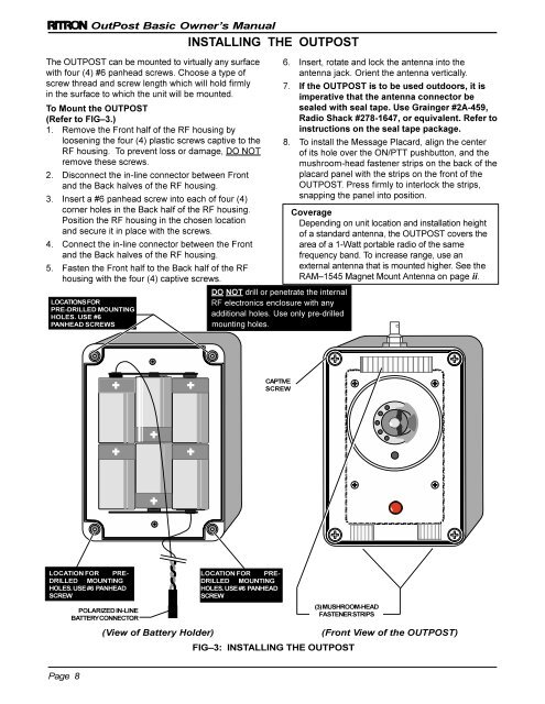
The OUTPOST can be mounted to virtually any surface<br />
with four (4) #6 panhead screws Choose a type of<br />
screw thread and screw length which will hold firmly<br />
in the surface to which the unit will be mounted<br />
To Mount the OUTPOST<br />
(Refer to FIG–3)<br />
1<br />
Remove the Front half of the RF housing by<br />
loosening the four (4) plastic screws captive to the<br />
RF housing To prevent loss or damage, DO NOT<br />
remove these screws<br />
2 Disconnect the in-line connector between Front<br />
and the Back halves of the RF housing<br />
3 Insert a #6 panhead screw into each of four (4)<br />
corner holes in the Back half of the RF housing<br />
Position the RF housing in the chosen location<br />
and secure it in place with the screws<br />
4 Connect the in-line connector between the Front<br />
and the Back halves of the RF housing<br />
5 Fasten the Front half to the Back half of the RF<br />
housing with the four (4) captive screws<br />
LOCATIONS FOR<br />
PRE-DRILLED MOUNTING<br />
HOLES USE #6<br />
PANHEAD SCREWS<br />
INSTALLING THE OUTPOST<br />
D<br />
6<br />
7<br />
8<br />
DO NOT drill or penetrate the internal<br />
RF electronics enclosure with any<br />
additional holes Use only pre-drilled<br />
mounting holes<br />
Insert, rotate and lock the antenna into the<br />
antenna jack Orient the antenna vertically<br />
If the OUTPOST is to be used outdoors, it is<br />
imperative that the antenna connector be<br />
sealed with seal tape Use Grainger #2A-459,<br />
Radio Shack #278-1647, or equivalent Refer to<br />
instructions on the seal tape package<br />
To install the Message Placard, align the center<br />
of its hole over the ON/PTT pushbutton, and the<br />
mushroom-head fastener strips on the back of the<br />
placard panel with the strips on the front of the<br />
OUTPOST Press firmly to interlock the strips,<br />
snapping the panel into position<br />
Coverage<br />
Depending on unit location and installation height<br />
of a standard antenna, the OUTPOST covers the<br />
area of a 1-Watt portable radio of the same<br />
frequency band To increase range, use an<br />
external antenna that is mounted higher See the<br />
RAM–1545 Magnet Mount Antenna on page ii<br />
CAPTIVE<br />
SCREW<br />
LOCATION FOR PRE-<br />
DRILLED MOUNTING<br />
HOLES USE #6 PANHEAD<br />
SCREW<br />
LOCATION FOR PRE-<br />
DRILLED MOUNTING<br />
HOLES USE #6 PANHEAD<br />
SCREW<br />
POLARIZED IN-LINE<br />
BATTERY CONNECTOR<br />
(3) MUSHROOM-HEAD<br />
FASTENER STRIPS<br />
(View of Battery Holder)<br />
(Front View of the OUTPOST)<br />
FIG–3: INSTALLING THE OUTPOST<br />
Page 8